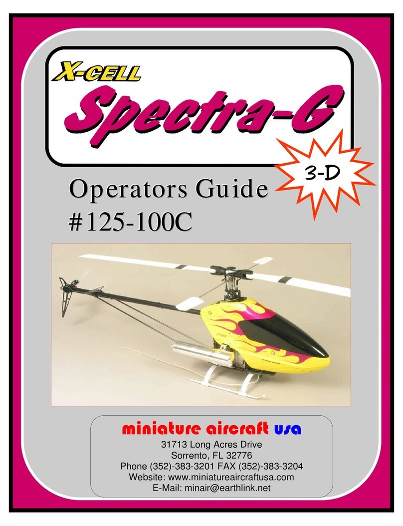
miniature aircraft X-CELL Spectra-G User manual


Page 2 of 67
R/C HELICOPTER SAFETY
A radio controlled model helicopter is a technically complex device that must be built and
operated with care. It is also a fascinating and challenging part of the R/C sport, the mastery of
which is very rewarding.
A model helicopter must be built exactly in accordance with the building instructions. The kit
manufacturer has spent much time and effort refining his product to make it reliable in operation
and easy to build. The essentially bolt together construction can proceed quite rapidly, giving the
builder a strong sense of accomplishment that encourages hasty progress from one construction
phase to the next, so that the completed model can be more quickly seen and enjoyed. It is
essential to recognize and guard against this tendency. Follow building instructions exactly.
Vibration and stress levels are high and all fasteners and attachments must be secure for safe
operation.
Note that this is the first use of the word SAFETY in these comments. Previously the kit
manufacturers efforts to ensure reliable operation were mentioned. That is ALL that he can do.
Safe operation is the responsibility of the builder/flyer and starts with careful construction and
continues with selection and installation of reliable radio equipment and engine.
The need for safety is nowhere greater than at the flying field. A number of guidelines for safe
flight have been developed by experienced flyers and are set down here. It is urged that they be
read, understood and followed.
GUIDELINES FOR SAFE R/C HELICOPTER FLIGHT
Fly only at approved flying fields and obey field regulations.
Follow frequency control procedures. Interference can be dangerous to all.
Know your radio. Check all transmitter functions before each flight.
Be aware that rotating blades are very dangerous and can cause serious injury.
Never fly near or above spectators or other modelers.
If a beginner, get help trimming the model first, and flight training later.
Don’t “track” the main blades by holding the tail boom. This is a temptation to builders who
cannot hover yet and is very dangerous.
Follow all recommended maintenance procedures for model, radio and engine.
WARNING
This helicopter is not a toy, but a complex flying machine that must be assembled with care
by a responsible individual. Failure to exert care in assembly, or radio or accessory
installation, may result in a model incapable of safe flight or ground operation. Rotating
components are an ever present danger and source of injury to operators and spectators.
Since the manufacturer and his agents have no control over the proper assembly and
operation of his products, no responsibility or liability can be assumed for their use.

Page 3 of 67
X-CELL LIMITED WARRANTY
The warranty covers defects in material or workmanship or missing components to the original
purchaser for 30 days from the date of purchase. Miniature Aircraft, USA will replace or repair,
at our discretion, the defective or missing component. Defective components must be returned to
us prior to replacement.
Any part, which has been improperly installed, abused, crash damaged or altered by
unauthorized agencies is not covered. Under no circumstances will the buyer be entitled to
consequential or incidental damages. The components used in this kit are made form
special materials designed for special applications and design strengths. We recommend
that all replacement parts be original parts manufactured by Miniature Aircraft, USA, to
ensure proper and safe operation of your model. Any part used which was manufactured
by any firm other than Miniature Aircraft, USA, VOIDS all warrantees of this product by
Miniature Aircraft, USA.
WARRANTY PROCEDURES
Mail all warranty information within 15 days of original purchase date. If service is required,
send the component in question (if not missing) together with a photocopy of your bill of sale
and an accurate description of the problem and part. Ship components fully insured and prepaid.
Miniature Aircraft, USA is not responsible for any shipping damages. We will, at our discretion,
notify you of any costs involved, or ship it COD. You are required to pay all postage,
shipping and insurance charges.
X-Cell Spectra-G warranty registration
Please print or type, filling in the information listed below and mail immediately
Model No:____________Serial No:____________________Price paid:____________________
Owners name:_________________________________________Age______________________
Address:______________________________________________Phone:___________________
City:_________________________State:_______________________Zip:__________________
Purchased from:________________________________________________________________
Dealer’s address________________________________________________________________
______________________________________________________________________________
Comments:____________________________________________________________________
______________________________________________________________________________
MINIATURE AIRCRAFT USA
31713 Long Acres Drive
Sorrento, FL 32776
Phone (352) 383-3201
FAX (352) 383-3204

Page 4 of 67
X-CELL Spectra G-3D
(with Tempest head)
INTRODUCTION
These instructions apply to the Spectra G-3D Kit #1025
Congratulations! You have purchased a quick assembling, high quality helicopter kit ideally
suited for beginner through expert pilots. Please pay particular attention to each assembly step.
SYSTEM REQUIREMENTS
A minimum five channel “helicopter” type radio with electronic swash plate mixing (eCCPM)
capability and three high quality servos (“digital” preferred due to their superior centering and
equality). You will also need a throttle servo. If you are using a governor, then select the servo
recommended by the governor manufacturer, otherwise use a good quality coreless servo.
A yaw rate gyro (basic or heading lock type) with a matched servo, to stabilize and assist in tail
rotor control. Select the unit best suited to choice of radio and budget- be aware that even a
beginner will appreciate the improved function of a top quality gyro, so choose wisely.
THE KIT PACKAGE
The kit includes detailed drawings showing all parts, part numbers, fastener information and
complete radio installation data. Metric hardware is used throughout with correct tensile strength
and heat treatment required for each position.
Each assembly step requires that only it’s corresponding parts bag be used, avoiding confusion
between similar appearing parts and fasteners for subsequent steps.
Also included is a bag of spare hardware, Allen wrenches (hex keys) and certain other special
tools to assist in assembly.
TOOLS AND/OR MATERIALS REQUIRED
The following tools and materials are suggested to assist in building the kit:
Screwdrivers - small straight and Phillips
Plier’s - small regular, needle nose, and forceps
Hand drill with drill bits
Open end wrench’s - 5.5mm (7/32"), 7.0mm (9/32"), 8.0mm (5/16")
Dremel tool with sanding drum and carbide disk
Masking tape
Metric ruler

Page 5 of 67
Small hammer
Vinyl two-sided tape - 1/8" thick (M.A./USA p/n 3869)
Slow and fast setting Cyanoacrylate (CA) adhesive
Heat gun
High quality synthetic grease (M.A./USA p/n 4707)
Light oil (teflon type M.A./USA p/n 4801)
Canopy finishing materials (described elsewhere in this document)
“C” clip pliers
The following are optional tools:
Ball link installation tool (M.A./USA p/n 0529)
5.0mm nutdriver (M.A./USA p/n 2957-1)
5.5mm nutdriver (M.A./USA p/n 2957-2)
7.0mm nutdriver (M.A./USA p/n 2957-4)
Flybar lock (M.A./USA p/n 0506)
Flybar alignment kit (M.A./USA p/n 0510-1)
Swashplate alignment tool (M.A./USA p/n 0513)
Pitch gauge (M.A./USA p/n 0526)
Custom hardened hex tools: 1.5mm (M.A./USA p/n 2985-1)
2.0mm (M.A./USA p/n 2985-2)
2.5mm (M.A./USA p/n 2985-3)
3.0mm (M.A./USA p/n 2985-5)
The following items are required or useful in the operation of any R/C helicopter:
A field charger for your various batteries.
Various selections of quality tools as used in the kit assembling steps.
Frequency flag displaying your radio frequency and color code (usually included with your
radio).
Academy of Model Aeronautics (AMA) membership (for those individuals not residing in the
USA, a membership in the model aeronautics organization of your country should be pursued).
Membership in the AMA will grant you the right to fly at and participate in events around the
country which take place at registered AMA sites. Additionally, this membership provides
certain liability insurance to the modeler. More information can be had by calling 1-800-435-
9262 or visiting the AMA website at www.modelaircraft.org.
ASSEMBLY INSTRUCTIONS
Please take the time to review all instructions and drawings before building the kit. Each step
will list bags, tools and parts required to proceed.
Any position calling for the installation of steel threaded hardware into non-locking threads will

Page 6 of 67
refer to the addition of Blue Locktite thread locker (included). Any position using steel hardware
into plastic will refer to the addition of slow Cyanoacrylate (CA) (not included) as a thread
locker. Always clean the threads with alcohol and use the locking material sparingly.
For individuals wishing to know, the following maximum torque values apply to metal-to-metal
positions on the model.
Bolt size NCM (metric) Inch/pounds (US)
M3 40.0 3.5
M4 70.0 6.2
This information is provided only for interest and in no way indicates that a torque wrench is
need to build the model.
When installing hardware into plastic, be aware that:
a) threads are forming, so hold the item straight while tightening.
b) you must stop tightening as soon as the flange or head contacts the plastic surface.
Frequently, the text will refer to items called “PEM” nuts. These are M2.5 and M3.0 threaded
steel inserts that are factory installed in both side frames and various frame channels used in the
kit. They are non-locking and require the use of Blue locktite on any related bolts or screws. Do
not attempt to remove them and avoid over-tightening hardware into them. They are quite secure
with only minimal tightening and Blue locktite.
ASSEMBLY SEQUENCE SUMMARY
Section: Subassembly:
I Building the rotor head
II Building the left main frame
III Installing the main shaft, main gear and front tail drive
IV Installing the right main frame
V Building the lower plate and installing the landing gear
VI Installing the fuel tank
VII Installing the swashplate, washout and rotor head assembly
VIII Building the tail rotor assembly
IX Building the tail boom assembly, boom supports and installation onto the main
mechanics
X Installing the radio system and pushrods
XI Preparing the canopy
XII Rotor blade selection
XIII Final mechanical and electronic set-up
XIV Final inspection

Page 7 of 67
XV Pre-flight information
XVI Starting and stopping procedure
XVII First flight adjustments
XVIII Troubleshooting guide
I. BUILDING THE ROTOR HEAD
Bags required: #1A, #1B, #1C, #1D, #1E, #1F, #1G and bag #9A
Tools or materials required:
Small Phillips screwdriver
Small hammer
Solvent (thinner or alcohol)
Loctite-Blue or Green
Slow cyanoacrylate glue (CA)
M1.3, 1.5, 2.5 and 4.0mm (2 each) Allen tools
“Q-Tip” cotton swabs or tissue
Needle nosed pliers or forceps
A few inch’s of masking tape
3/8" or similar socket with an O.D. of 14.0 to 16.0mm
Grease
Step 1: Installing the Flybar and Control Arms
Parts required:
Qty Part number Part description Found in bag
2 #0840-7 4mm Washer 1B
2 #123-20 Flybar support tube assy. 1A
2 #566-1 Flybar 11A
2 #0109 M3X8 Threaded balls 1B
1 #0572-7 Aluminum standoff 1B
2 #122-03 Flybar control arm 1B
2 #0063 M3X10 Socket head bolts 1B
2 #0067 M3X14 Socket head bolts 1B
2 #122-18 Threaded s/s Spacer 1B

Page 8 of 67
1 #0051 M3X3 Socket set screws 1B
Refer to drawings #1A and #1B
A) Select two #122-03 flybar control arms, two #0063 M3X10 socket head bolts, two #122-18
threaded s/s spacers, two #0572-7 aluminum standoffs and two #0109 M3X8 threaded balls.
Assemble each flybar control arm per the drawing. Tighten securely using blue loctite.
B) Note: Each flybar control arm #122-03 contains three optional positions. Generally, the
center hole will be used. But, if increased paddle control is desired, the inside hole may be used.
Or, if less paddle control is desired, the outer hole may be used.
C) Study the drawing for the orientation of each flybar control arm assembly. Select the flybar
#0566-1 and insert it into the flybar support tube assembly bearings on the rotor head block.
Visually center the flybar. Select one #0840-7 4mm washer and one flybar assembly. Slide the
washer followed by the arm onto the flybar, up to the bearing. Repeat this process on the
opposite side. Apply blue loctite to the two #0051 M3X3 socket set screws and instal one into
each control arm. Carefully measure the assembly until the lengths are equal and no freeplay
exists in and out of the head block. Align each flybar control arm until they are level with each
other, then securely tighten each set screw.
D) Select two #0067 bolts and temporarily thread each into holes provided near the base of the
head block. Note that even though the holes are threaded full depth, the bolts instal from the side
closest to the slot at each corner. Do not tighten until section VII step 2E.
Step 2: Installing the Bell Hiller mixers
Parts required:
Qty Part number Part description Found in bag
2 #0113 M3X10.5 Threaded double ball (long threads) 1C
2 #0597-1 M3 X 0.126" X 0.187 brass spacer 1C
2 #0109 M3X8 Threaded ball 1C
2 #0050-1 M2.5X3 Socket set screws 1C
2 #123-24 Pitch arms 1C
2 #0597-3 M3 X 0.186" X 0.188" Brass spacer 1C
2 #0115 M3X10.5 Threaded ball 1C
4 #106-02 M3X7X3 Flanged ball bearings 1C

Page 9 of 67
2 #0091 M3X16 Phillips bolt 1C
2 #0562-1 M3X0.09 Shim washer 1C
2 #123-26 Bell Hiller mixers 1C
Refer to drawing #1C
A) Press one #106-02 M3X7X3 flanged ball bearing into each #123-26 bell mixer. It is
recommended that the bearing be installed first in the same side of each mixer. A light amount of
green loctite is mandatory on the outer race of each bearing. Insert one #0587-3 brass spacer into
each bearing cavity opposite the installed bearing followed by another #106-02 bearing in the
opposite side of the bearing cavity in the Bell mixer.
B) Install one #0109 threaded ball and one #0115 threaded ball into each Bell mixer using blue
loctite. Tighten securely.
Notes about mixing ratios and setup:
The Bell mixers, flybar tube and pitch arms offer various mixing ratio options. The
following guides will help you select these options.
Bell mixers: The Bell mixers may be installed on the pitch arms in one of two positions:
Position one: Raised bearing boss side facing away from the pitch arm.
Position two: Raised bearing boss side facing the pitch arm.
Flybar tube: The flybar tube offers two threaded hole positions on each end of the tube for
location of the double threaded balls:
Position 1: Inside holes
- Increased flybar input
- Increased pitch to flybar
- Identical ratio as standard Extreme rotor head
Position 2: Outside holes
- Medium flybar input
- Medium pitch to flybar
The following mixing ratios are possible with the combination of positions chosen:

Page 10 of 67
Bell mixer mounting
location Flybar tube control ball location
Inside hole Outside hole
Position 1 1:0.61 1:0.56
Position 2 1:0.62 1:0.58
Table 1: Head input mixing ratios
Pitch arms: Each pitch arm has three threaded hole positions for mounting the Bell mixers. The
center hole is zero offset. The left hole (closest to the main shaft) is negative offset. And the right
hole (furthest from the main shaft) is positive offset.
Position 1: Zero offset
- Neutral corrections due to wind influence.
Position 2: Positive offset
- Slightly improved high speed tracking
Position 3: Negative offset
- Improved hovering characteristics in the wind.
Note: The pitch arm offset is a pilot preference. This may vary due to combinations of blades
and head speeds chosen. Choose by trial and error.
C. Select two #0113 threaded double balls and two #0587-1 brass spacers. Install a brass spacer
on each double ball and apply blue loctite to the exposed threads. Install one prepared double
ball into the chosen position on the flybar tube. Repeat for the opposite end of the flybar tube.
Tighten securely.
D. Using blue loctite, install each Bell mixer onto the #123-24 pitch arms with one #0091
M3X16 Phillips bolt and one #0562-1 M3 X 0.09" shim washer. Each unit should pivot freely
after tightening. As a safety precaution, install one #0050-1 M2.5X3 socket set screw into the top
side of each pitch arm at the chosen offset mounting hole location of the Bell mixers.
Step 3: Installing the upper head block assembly
Parts required:
Qty Part number Part description Found in bag
1 #122-14 Upper head block 1A

Page 11 of 67
1 #122-17 Head button 1D
4 #0064 M3X8 Button head bolt 1D
2 #0062 M3X10 Flat head bolt 1D
1 Pre-assembled lower head block from step 1 1D
2 #0687 M3 X 0.086" X 0.158" steel spacer 1D
Refer to drawing #1D
A. The upper head block #122-14 is symmetrical by design, therefore it may be installed on
either side. Slide the upper head block onto the pre-assembled lower head block assembly. It
may be neccessary to lightly tap both components together. If so then use a plastic or rubber
mallet. If any metal device is used then protect the parts with a piece of hardwood. Secure
together with four #0064 M3X8 button head bolts using blue loctite.
B. Install the #122-17 head button to the top of the lower head block #122-15 using two #0062
M3X10 flat head bolts and two #0687 steel spacers. Use blue loctite.
Step 4: Assembling the main blade mounts and head axle
Parts required:
Qty Part number Part description Found in bag
2 #0011 M5 washer 1E
2 #0023 M5 Locknuts 1E
2 #0060 M3X5 Socket head bolt 1E
4 #0061 M3X8 Socket head bolt 1E
2 #0086 M5X12 Flanged socket head bolt 1E
4 #0319 M8X16X5 Ball bearing 1E
2 #0329 M8X13X0.25 Shim 1E
2 #0331 M8X13X0.5 Shim 1E
2 #0426 M8X13X0.1 Shim 1E
2 #0840-10 M8X12X0.8 Spacer 1E
2 #0840-12 3-piece thrust bearing 1E

Page 12 of 67
4 #0844-2 70-D Rubber O-rings 1E
2 #0848-4 Aluminum retainer sleeves 1E
2 #0848-3 M8X12X2 Hinge ring 1E
1 #122-02 Head axle 1E
2 #122-11 Machined main blade mounts 1E
2 #122-12 M5 Main blade bolts 1E
2 #122-13 M5 Fiber blade spacers 1E
Refer to drawings #1E and #1F
Note: Two different hardnesses of O-ring dampeners and three sets of shim thicknesses are
provided. The specific dampening may vary depending on the main blades chosen or your
personal flying style. We suggest starting with the O-rings and shims described in the following
building sequence.
-Standard dampening 4 70-D O-rings (#0844-2)
2 0.050" Shims (#0331)
-Stiffer dampening 2 70-D O-rings (#0844-2)
2 80-D O-rings (#0844)
Various combinations of the #0329, #0331 or #0426 shims
A. Select one #122-02 head axle and two #0844-2 70-D rubber O-rings. Do not lubricate the O-
rings with any oil, grease or Vaseline. If aid is needed in installing the O-rings, use only
liquid which will evaporate, such as window cleaner or alcohol. Center the head axle in the
#122-14 upper head block. Slide two #0844-2 70-D rubber O-rings on each side of the head axle.
Push the O-rings into the upper head block while centering the head axle.
B. On one end of the head axle, assemble the following components in the sequence shown.
1) One #0331 M8X13X0.5 Shim
2) One #0848-3 Hinged ring (cupped side facing the O-rings)
3) One #0319 M8x16x5 Ball bearing
4) One #0848-4 Aluminum retainer sleeve (counter bore side facing the bearing)
5) One #0848-12 Thrust bearing (3 pieces)
Special note: The thrust bearing will contain one outer ring that has a smaller I.D. hole
than the other outer ring. Identify this feature before proceeding. Install the larger I.D.
outer ring with the grooved side away from the retainer sleeve. Apply grease to the
groove. Next, slide the ball cage into position. Apply more grease to the ball cage. Slide

Page 13 of 67
the remaining small I.D. outer ring into position with the grooved side facing the ball
cage.
6) One #0848-10 M8X12X0.8 Spacer
7) One #0319 M8X16X5 Ball bearing
8) One #0011 M5 Washer
9) One M5X12 Flanged socket head bolt
Note: Sparingly apply blue loctite to the threads and install into the head axel.
Tighten only finger tight at this time.
C. Repeat step “B” on the opposite end of the head axle. Tighten both #0086 bolts using two
4mm allen wrenches.
D. Slide one #122-11 blade mount into position on the bearing assembly and align the holes with
those of the aluminum retainer sleeve #0848-4. On the side of the blade mount with only one
hole, install one #0060 M3X5 socket head bolt. Only finger tighten at this time.
E. Select two pre-assembled pitch arms from step 1C and four #0061 M3X8 socket head bolts.
Study the drawings and position the assembled pitch arms into the milled groove on the side of
the #122-11 machined main blade mounts. Using two #0061 M3X8 socket head bolts on each
arm. Use blue loctite. Note: the pitch arm is a light press fit into the blade grip. Start to
thread one or both #0061 bolts a few turns with a small amount of blue loctite. Using a small tool
handle or a wooden block, tap the pitch arm into place. Moderately tighten both #0061 bolts into
each arm. Remove the previously installed #0060 bolt, add blue loctite and moderately tighten.
F. Temporarily install the two #0086-2 M5 blade bolts, two #0023 M5 locknuts and two #122-13
fiber blade spacers.
Step 5: Assembly of the flybar paddles
Parts required:
Qty Part number Part description Found in bag
2 #0871-5 Sport paddles 1G
Refer to drawing #1G
Measure 22 mm inward from each flybar end and mark with tape. The flybar is self threading
into the paddles and the goal is to have each paddle level to the other and the flybar control arms.
Note, if your chosen option was to angle the flybar arms downwards, then the visual line for
alignment will be a horizontal line drawn through and connecting each ball on each control arm.
A useful tool for aligning the paddles is the #0510-1 paddle gauge kit. Slow CA or epoxy is used

Page 14 of 67
for a paddle locking device, allowing sufficient cure time to simplify aligning the component.
Install each paddle as indicated and remove the tape. If all steps were accurately performed, then
it should be evident that by holding the head vertical and releasing the flybar, the paddles will
appear balanced. If not, then a small piece of vinyl tape can be applied to the “light” paddle. It is
also possible to fine tune the balance by lightly sanding the tip of the “heavy” paddle.
II. BUILDING THE LEFT MAIN FRAME
Bags required: #2A, #2B, #3D
Tools or materials required:
M2.5 Allen tool
M5.5 (7/32") flat wrench
Slow CA adhesive (glue)
Installing the left frame components
Parts required:
Qty Part number Part description Found in bag
1 #0019 M3 Locknuts 2B
3 #0063 M3X10 Socket head bolt 2B
2 #0032 M2.9X9.5 Phillips self tapping screws 2B
1 #0053-5 M3X16 Socket set screw 2B
10 #0060-1 M3X6 Socket head bolt 2B
8 #0061 M3X8 Socket head bolt 2B
1 #0169 Bell crank pivot stud (black) 2B
1 #0874-1 Swashplate anti-rotation 2B
9 #115-20 M5X20 spacers 2B
1 #120-12 Upper main shaft block 2B
1 #120-8 Lower main shaft block 2B
1 #125-10 Vertical rear channel (216mm) w/bearing 2A
2 #125-12 ½" channels (12.7mm) 2B
1 #125-32 Front doubler plate strip 2B

Page 15 of 67
1 #125-33 Rear doubler plate strip 2B
1 #122-27 Rear canopy mount 2B
1 #0862-1 Rudder bell crank pivot stud 2B
1 #115-18 Main shaft bearing block 2B
2 #0089-1 M3X8 Hex bolt 2B
1 #125-15 Left main frame 2A
1 #120-10 Main shaft 3D
1 #125-30 Throttle servo plate 2B
1 #106-41 Front Canopy Mount 2B
SPECIAL NOTES:
1) This kit allows the motor to be mounted such that the cylinder is either forward facing or
rearward. If you elect to mount the motor with the cylinder facing forwards, it is suggested
that canopy mounts be mounted in the forward alternate mounting positions. Labeled “A” on
the drawings. Use the following hardware for mounting the rear canopy studs:
* #0089-1 M3X8 hex head bolts to secure the canopy studs to the frame. Omit the use
of the #0053-5 M3X16 socket set screw.
* #0060-1 M3X6 socket bolt in the upper hole of the rear vertical channel.
2) The throttle servo plate #125-30 is mounted on the left frame for a rearward facing engine.
If a forward facing position is chosen, mount the #125-32 doubler plate strip on the left frame
as shown in position “A” on the drawing. In this case the #125-30 plate will be mounted later
in step 4.
Refer to drawing #2A
A) Select the #125-15 left main frame, one #125-10 vertical rear channel, one #0061 M3X8
socket head bolt, one #0862-1 rudder bell crank pivot stud, one #0053-5 M3X16 socket set
screw and one #122-27 rear canopy mount.
Using red or green loctite, install the #0053-5 set screw into the #122-27 canopy mount. At
least 6mm of the threads must protrude out of the canopy mount. Allow to thoroughly dry.
Orient the main frame and rear channel as shown. Install the required hardware. Use blue
loctite on the center and upper hole positions. Tighten securely.

Page 16 of 67
B) Select one #0169 bell crank pivot stud and one #115-20 frame spacer. Note the position of
the pivot stud outside the frame. Using loctite, install the pivot stud with the frame spacer on
the inside and tighten securely.
C) Install the #125-30 throttle servo plate or the #125-32 doubler plate strip “A” to the outside
of the left frame using two #0061 M3X8 socket bolts and two #115-20 frame spacers. It is
suggested that an M3 bolt be installed in one of the lower front holes of the doubler plate and
the main frame, for alignment purposes only. Tighten securely using blue loctite and remove
the M3 bolt if so installed for alignment.
D) Install the #125-33 rear doubler plate onto the outside of the left frame, one #0019 M3 lock
nut, one #0061-1 M3X6 socket bolt, one #0061 M3X8 socket bolt, one #0063 M3X10 socket
bolt and one #115-20 M5X20 spacer. As with step “C”, temporarily install an M3 bolt into
one of the lower rear holes of the doubler plate and the mainframe. Use blue loctite on all
hardware except the #0019 nut and the #0063 bolt securing the lower side of the rear channel.
Tighten securely.
E) As per the drawing install one #106-41 front canopy stud using #0089-1 M3X8 hex head
bolt. Tighten securely using blue loctite.
F) As per the drawing, install five #115-20 frame spacers using five #0060-1 M3X6 socket
bolts. Tighten securely using blue loctite.
G) Install two #125-12 one half inch (12.7mm) channels using two #0060-1 m3x6 socket
bolts. Tighten securely using blue loctite.
H) Select the #0874-1 swashplate guide and two #0032 M2.9X9.5 phillips self-tapping
screws. Note the location and install the guide using slow CA adhesive on each screw. Check
that the guide is mounted vertically.
I) Install the #120-12 upper main shaft bearing block (hump side upward) using two #0063
M3X10 socket head bolts and blue loctite. Do not fully tighten at this time.
J) Install the #120-8 lower main shaft bearing block as shown using one #0060-1 socket head
bolt and two #0061 M3X8 socket head bolts. Use blue loctite. Do not fully tighten at this
time.
K) Install one #115-18 bearing block using two #0061 M3X8 socket bolts.
L) Remove the #120-10 main shaft from bag 3D. Slide it down through the bearing blocks and
securely tighten all the bolts in both blocks. Only lightly tighten the bolts in the #115-18
lower bearing block. These bolts will be removed later when installing the clutch bell
alignment plates.

Page 17 of 67
III. INSTALLING THE MAIN SHAFT, MAIN GEAR AND FRONT TAIL DRIVE
Bags required: #3A, #3B, #3C, #3D
Tools or materials required:
M1.5, 2.0 and 2.5 allen tools
M5.5 flat wrench
Tri-flow #4801 or automatic transmission fluid (ATF)
(optional) feeler gauge
Step 1: Installing the front tail rotor drive gear and shaft
Parts required:
Qty Part number Part description Found in
bag
3 #0051 M3X3 socket set screws 3A
1 #0232 15 tooth bevel gear 3A
1 #0237 M5 retaining collar 3A
1 120-9 Front transmission shaft 3A
Refer to drawing #3A
A) Select one #120-9 front transmission shaft, one #0237 retaining collar and one #0232 15
tooth bevel gear. Examine the drawing and note the orientation of each part. Insert the #120-
9 front transmission shaft from the rear of the main frame through the bearing housed in the
#125-10 vertical rear channel. With 25 to 30mm exposed in front of the bearing, slide the
#0237 retaining collar followed by the #0232 bevel gear onto the shaft.
B) Select one #0051 M3X3 socket set screw, apply blue loctite and partially thread into the
#0237 retaining collar. Push the shaft forward into the #120-8 front transmission bearing
block. Apply forward pressure on the white delrin portion of the #120-9 transmission shaft
while pressing rearward on the #0237 retaining collar. Tighten the #0051 M3X3 socket set
screw within the collar. Check to see that no end play exists within the shaft. If there is end
play, then reposition the collar to ensure no end play exists.
C) Select two #0051 M3X3 socket set screws. Note the #120-9 front transmission shaft has
a flat for a set screw securing the #0232 bevel gear. Install one #0051 M3X3 set screw into
the gear, tightening enough to be certain it has engaged the flat and the gear can be moved

Page 18 of 67
for final positioning. Final gear position can be determined after the main gear is installed,
observing the rule that the bevel gear be centered within the main gear. Which ever method
is utilized, always remember to install the remaining #0051 M3X3 socket set screw with
blue loctite then remove and loctite the first set screw and double check the contact within
the flat provided.
Step 2: Assemble the constant drive autorotation upper section
Parts required:
Qty Part
number Part description Found in bag
8 #0088-1 M3X5 Flat head screws 3B
1 #0866-5 70 tooth upper bevel gear 3B
1 #0866-6 Upper gear mounting base w/main shaft sleeve 3B
Refer to drawing #3B
A) Select eight #0088-1 M3X5 flat head screws and prepare each with blue loctite. Select
the #0866-5 bevel gear and #0866-6 mounting base. Press the mounting base downward into
the upper surface of the bevel gear, aligning the holes as you proceed. From the underside,
install the eight #0088-1 M5X3 flat head screws, tighten them a little at a time in a “star”
pattern. Tighten all with light torque.
Step 3: Install the outer main gear onto the autorotation hub
Parts required:
Qty Part
number Part description Found in
bag
4 #0088 M3X8 flat socket head bolts 3C
1 #0865-93 93T outer main gear 3C
2 #0866-10 M14.0-20.0X0.2 shim rings 3C
1 #0866-11 M14 Teflon O-rings 3C
1 #0866-4 Lower housing w/Sprag bearing 3C
Refer to drawing #3C

Page 19 of 67
A) Select four #0088 bolts and prepare with blue loctite. Select the outer main gear and note
the four countersunk holes on the upper surface. Only the countersunk holes will be utilized.
Press the gear atop the upper housing, align the countersunk holes, install the four bolts and
tighten with light torque.
B) Select one #0866-10 shim ring and apply a little grease to each side. Set this atop the Oilite
bushing (visible at the top of the upper housing, protruding through the main gear).
C) Select another #0866-10 shim ring, apply grease and slide upward to meet the gear mount.
Select one #0866-11 Teflon O-ring and install it next to the shim ring. Set the main gear/sprag
housing assembly upright on the table. Insert the upper gear/sleeve assembly downward into
the sprag clutch. When it makes contact, rotate the upper assembly slightly clockwise while
lightly pressing downward. When it drops inward about 5.0mm (easily noticed as you rotate
and push downward) lift the combined parts off the table. Hold them inverted at about a 45
degree angle and apply a liberal amount of Tri-flow oil to that portion of the sprag clutch that
is visible just inside the lower Oilite bushing in the lower hub. Rotate the unit as you apply
more oil. The unit will hold about 7 to 8cc’s (1/4 ounce) of oil. When oiling is completed,
press the upper gear fully into the lower gear and wipe away any excess oil.
Note: never force the main sleeve into the sprag clutch. If it does not insert easily while
rotating, look from beneath the sprag to be sure that the cogs look uniformly positioned.
They are only retained by an outer spring and it is possible to dislocate one during
insertion. If necessary, remove the sprag clutch from the housing and it will return to
it’s proper configuration.
Step 4: Installing the main shaft and main gear/autorotation assembly
Parts required:
Qty Part number Part description Found in bag
1 #0057 M4X4 Socket head set screw 3D
2 #0059-1 M2.5X6 Socket head bolts 3D
1 #0840-6 M3X20 Dowel pin 3D
1 #0866-10 M14.0X20.0X0.2 Shim ring 3D
1 #0866-11 M14 Teflon O-ring 3D
1 #0866-12 retaining collar (black) 3D
1 #0866-13 M14X20.0X0.1 Shim ring 3D
1 #120-10 Main shaft 3D
2 #0875 Split type main shaft collars 3D

Page 20 of 67
Refer to drawing #3D
A) Select the #120-10 main shaft. Note: the main shaft must be installed per the drawing.
Apply a little light oil to a cloth a briskly wipe down the shaft. This will remove the
protective coating. It is suggested that a trial fit of the main shaft be performed prior to
assembling the main shaft components. It may be necessary to loosen the lower block for
alignment, and re-tighten with the main shaft in place. As noted above, insert the correct end
of the main shaft into the upper main shaft bearing block at the top of the mainframe. Slide
it through so that 20 to 30mm is exposed below the bearing block.
B) Select two #0875 slit type main shaft collars. Examine the collars. One end of each collar
has a flat surface with a 0.3mm raised step near the bore. This end is always to face a ball
bearing. Using these criteria, slide two split collars onto the main shaft exposed below the
upper bearing block. The upper collar should have it’s flat surface (with step) facing up to
the underside of the upper bearing block and the lower collar should “face” the bearing in
the middle block. Slide the main shaft further downward into and through the middle
bearing block until about 6 to 7mm is exposed below.
C) Select the previously assembled autorotation, the #0840-6 dowel pin, the #0866-10 shim
ring, the #0866-11 Teflon O-ring and the #0866-12 collar. It should now be determined
which (or both) shim rings (#0866-10 and/or #0866-13) are required. Invert the autorotation
assembly and note the Oilite bearing exposed at the base of the housing. A shim ring should
always be placed next to this bushing. As a trial, install the #0866-13 M14.0X20X0.1 shim
ring followed by the teflon O-ring and the black retaining collar. Temporarily insert the
#0840-6 dowel pin through the collar (large I.D. hole) and into the autorotation sleeve.
Rotate the outer main gear against the inner and check for smooth rotation. Move the gear
up and down between the upper gear and the retaining collar. The desired situation is to
have the gear rotate freely but have very little up/down play. If it is too loose, substitute
shim ring #0866-10 for shim ring #0866-13. If there is no free play and the rotation is with
very light friction, it can remain as is since the teflon O-rings will break in quickly. It should
be noted that there is no operational problem or risk even if the unit develops as much as
0.5mm of free play (at your option the O-rings could be replaced or shim rings added).
When the correct shim(s) have been determined, remove the dowel pin, retaining collar, O-
rings and the shim(s). Apply a little grease to each side of the shim(s) and reinstall all items
except the dowel pin.
D) Slide the autorotation unit into position and slide the main shaft downward into the lower
bearing block. Align the holes within the #0866-12 retaining collar, the sleeve on the #0866-
6 and the lower main shaft hole. Note: that the #0866-12 retaining collar has one large hole
and one small hole. The large hole is for the insertion of the #0840-6 M3x20 dowel pin and
the subsequent #0057 M4X4 socket set screw. The small hole is for removal of the pin using
a 1.5mm allen tool or similar device. Insert the #0840-6 dowel pin as shown in the
drawings. The pin should easily slide in far enough to allow installation of the set screw. If
not, then there are two possible causes and various steps to cure the problem:
Table of contents
Other miniature aircraft Toy manuals

miniature aircraft
miniature aircraft X-cell Spectra-G 125-100c Manual

miniature aircraft
miniature aircraft X-Cell Whiplash MA1033 User manual

miniature aircraft
miniature aircraft X-Cell Stratus User manual

miniature aircraft
miniature aircraft X-Cell Furion 6 User manual

miniature aircraft
miniature aircraft X-Cell Ion-X2 User manual

miniature aircraft
miniature aircraft X-CELL WHIPLASH MA1033-3 User manual

miniature aircraft
miniature aircraft X-Cell Whiplash User manual

miniature aircraft
miniature aircraft X-Cell Whiplash User manual

miniature aircraft
miniature aircraft X-Cell Stratus User manual

miniature aircraft
miniature aircraft Fury 55 X-CELL User manual