Page 3/4
Form No. FX_062098 18.12.04 Rev 18.1
© 2018 | Minimax Fire Protection | 321 Industrial Park Dr. | Hastings, MI 49058 | www.minimax-re.com
Figure 1: Identification of Custom Paint for Concealed Covers
All custom color painted cover plates will have
an identifying label affixed to the inside of the
cover that indicates the custom color and will
have a representative sample (a paint dot) of
the paint on the label.
F
A
C
T
O
R
Y
A
P
P
L
I
E
D
C
U
S
T
O
M
P
A
I
N
T
C
O
L
O
R
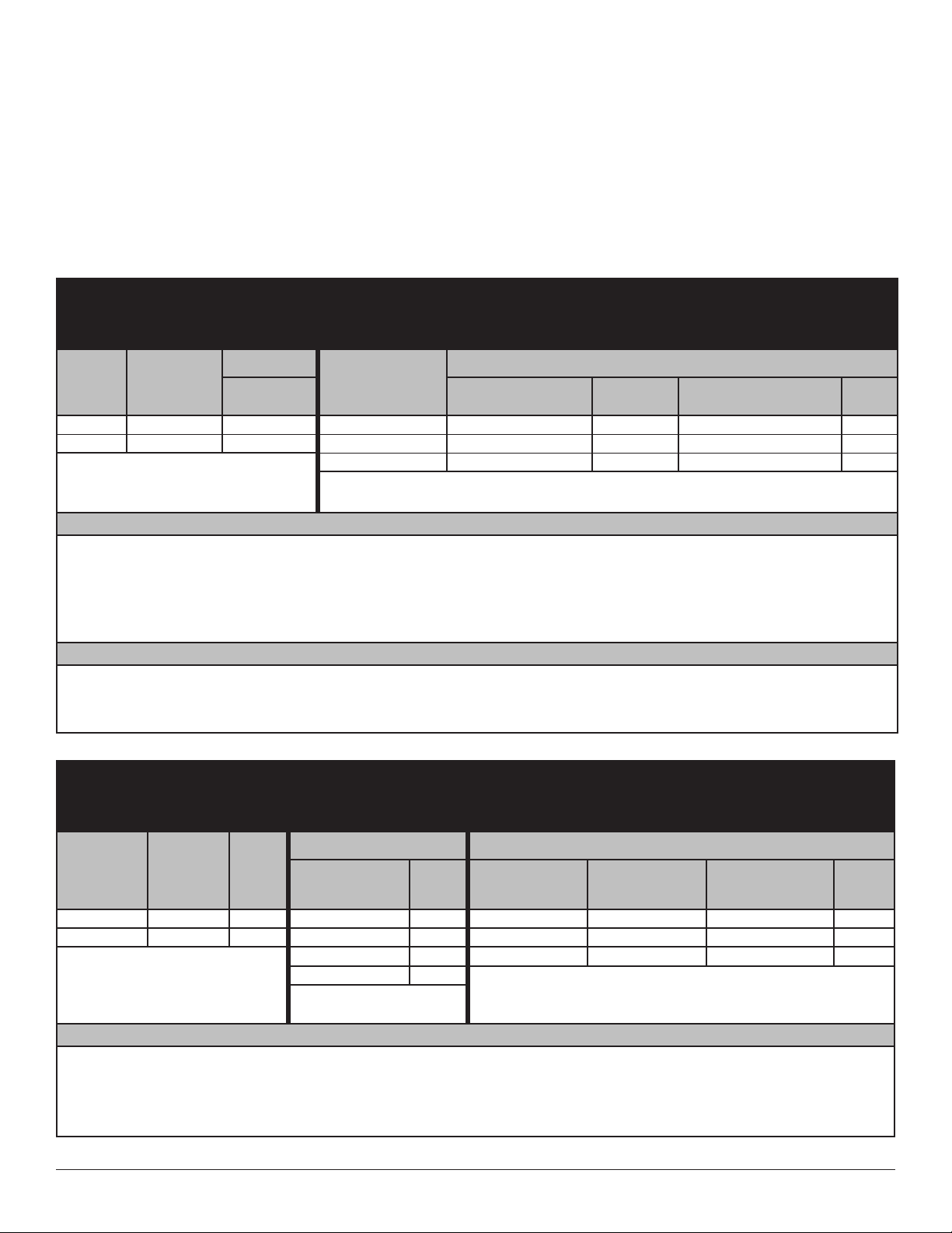
Approval Chart
Quick Response Concealed Pendent MRI Sprinklers
Sprinkler
Base Part
Number1
SIN
Thread Size Nominal
K-Factor Maximum Water
Working Pressure
Listings and Approvals3
(Refer also to Design Criteria)
NPT Inch U.S. metric2cULus4
61286A MX8462 1/2 5.6 80.6 175 psi (12 bar) AW1, BX1
61288A MX8464 3/4 8.0 115.2 175 psi (12 bar) AW1, BX1
Sprinkler Temperature Ratings
A - 155°F (68°C)
B - 175°F (79°C) and 200°F (93°C)
Cover Plate Assembly Temperature Ratings5
W - 135°F (57°C) cover 613651or 613661(large diameter)
X - 165°F (74°C) cover 613651or 613661(large diameter)
Cover Plate Assembly Finishes6
1 - Polished Chrome, Brushed Chrome, Bright
Brass, Antique Brass, Brushed Brass,
Brushed Copper, Painted White, Painted
Ivory, or Painted Black
Footnotes
1Part number shown is the base part number. For complete part number, refer to current price list schedule.
2Metric K-factor measurement shown is when pressure is measured in Bar. When pressure is measured in kPa, divide the metric K-factor shown by 10.0.
3 This chart shows the listings and approvals available at the time of printing. Other approvals may be in process. Check with the manufacturer for any
additional approvals.
4Listed by Underwriter’s Laboratories for use in the U.S. and Canada.
5The 135°F cover has an orange label. The 165°F cover has a white label.
6Painted finish consists of Polyester Baked Enamel. Other paint colors are available on request with the same listings as the standard paint colors.
Listings and approvals apply for any paint manufacturer. Contact Minimax Fire Protection for additional information.
NOTE: Custom colors are indicated on a label inside the cover assembly. Refer to Figure 1.
Design Criteria
(Also refer to the Approval Chart.)
cULus Listing Requirements:
Concealed Pendent MRI Sprinklers were subjected to magnetic field interaction testing and determined to be MRI conditional according to the termi-
nology specified in ASTM International, Designation F2502-15. These sprinklers are intended for use in a high magnetic field environment according
to the following conditions:
1. Static magnetic field of 3-Tesla or less
2. Highest spatial gradient magnetic field of 330-Gauss/cm or less
Sprinklers MX8462 and MX8464 are cULus Listed for installation in accordance with the latest edition of NFPA 13 for standard coverage pendent spray
sprinklers as indicated below.
• For hazard occupancies up to and including Ordinary Hazard, Group II.
• Protection areas and maximum spacing shall be in accordance with the tables provided in NFPA 13. Maximum spacing allowed is 15 ft. (4.6 m).
• Minimum spacing allowed is 6 ft. (1.8 m) unless baffles are installed in accordance with NFPA 13.
• Minimum distance from walls is 4 in. (102 mm).
• Maximum distance from walls shall be no more than one-half of the allowable distance between sprinklers. The distance shall be measured
perpendicular to the wall.
• The sprinkler obstruction rules contained in NFPA 13 for standard coverage pendent spray sprinklers must be followed.
NOTE: Concealed sprinklers must be installed in neutral or negative pressure plenums only.
IMPORTANT: Always refer to Form No. FX_091699 - Care and Handling of Sprinklers. Also refer to Form No. FX_080614 for
general care, installation, and maintenance information. Minimax Fire Protection sprinklers are to be installed in accordance
with the latest edition of Minimax Fire Protection technical data, the appropriate standards of NFPA or other similar organiza-
tions, and also with the provisions of governmental codes, ordinances, and standards, whenever applicable.