LIT-053 RevE 9/19/03 4:06 PM Page 2
Fig.7
Nozzle Removal
Post
2,1
2,8
3,4
4,1
2,1
2,8
3,4
4,1
2,1
2,8
3,4
4,1
2,1
2,8
3,4
4,1
2,1
2,8
3,4
4,1
2,1
2,8
3,4
4,1
2,1
2,8
3,4
4,1
2,8
3,4
4,1
4,8
206
275
344
413
206
275
344
413
206
275
344
413
206
275
344
413
206
275
344
413
206
275
344
413
206
275
344
413
275
344
413
482
0,20
0,23
0,27
0,30
0,27
0,32
0,36
0,41
0,36
0,41
0,45
0,50
0,45
0,55
0,61
0,66
0,59
0,68
0,77
0,84
0,73
0,84
0,95
1,04
0,95
1,11
1,25
1,36
1,36
1,54
1,73
1,86
3,4
3,8
4,5
4,9
4,5
5,3
6,1
6,8
6,1
6,8
7,6
8,3
7,6
9,1
10,2
11,0
9,8
11,4
12,9
14,0
12,1
14,0
15,9
17,4
15,9
18,5
20,8
22,7
22,7
25,7
28,8
31,0
9,1
9,4
9,4
9,8
9,8
10,1
10,4
10,4
10,4
11,0
11,6
11,6
11,0
11,6
12,2
12,2
11,0
12,2
12,8
12,8
11,3
12,2
13,1
13,4
10,7
12,2
13,1
13,4
12,5
13,4
13,7
14,3
1.0
Nozzle m
3
/hr.kPaBars l/min
Radius
m
Pressure Flow
Standard
Nozzles - Metric
1.5
2.0
3.0
3.5
4.0
6.0
8.0
NOZZLE INSTALLATION
1. Insert the plastic key end of the Hunter wrench into the lifting socket of the
sprinkler and turn 90º. Pull the riser up to gain access to the nozzle socket
(Fig. 8).
2. Using the hex key of the Hunter wrench, turn the radius adjustment screw
(Fig.6) counterclockwise to be sure it is not blocking the nozzle socket opening.
If a nozzle is already installed, it can be removed by backing out the adjustment
screw and turning on the water, or by pulling outward on the nozzle removal
post with a pair of needle-nosed pliers.
3. Slip the desired nozzle into the nozzle socket (Fig.7). Note that the socket is
angled up 25º.Then tighten the nozzle range screw.The triangle on the
rubber cover will always indicate the location of the nozzle and direction of
water flow when the sprinkler is retracted.
®
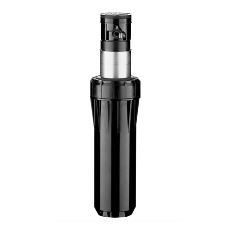
Institutional Series™ I-10 & I-20
Ultra
Gear-Driven Sprinklers
ALIGNINGTHE RIGHT (FIXED) SIDE OF ARC
If the right side of the arc is not properly aligned, the results may be a wet
walkway or a dry turf area.The right side arc can easily be realigned. One way
to realign the right stop is to turn the whole sprinkler body assembly and the
fitting below it, left or right to the desired position.This may require temporary
removal of the soil around the sprinkler to allow you to grip the sprinkler housing.
Nozzle GPM
Radius
ft.
PSI
30
40
50
60
30
40
50
60
30
40
50
60
30
40
50
60
2.0LA
25'
27'
28'
30'
27'
30'
33'
35'
29'
32'
35'
37'
31'
34'
37'
38'
1.6
1.9
2.1
2.3
2.1
2.5
2.8
3.0
2.8
3.1
3.5
3.8
3.4
3.9
4.4
4.7
2.5LA
3.5LA
4.5LA
Nozzle GPM
Radius
ft.
PSI
30
40
50
60
30
40
50
60
30
40
50
60
30
40
50
60
30
40
50
60
30
40
50
60
30
40
50
60
40
50
60
70
30'
31'
31'
32'
32'
33'
34'
34'
34'
36'
38'
38'
36'
38'
40'
40'
36'
40'
42'
42'
37'
40'
43'
44'
35'
40'
43'
44'
41'
44'
45'
47'
.9
1.0
1.2
1.3
1.2
1.4
1.6
1.8
1.6
1.8
2.0
2.2
2.0
2.4
2.7
2.9
2.6
3.0
3.4
3.7
3.2
3.7
4.2
4.6
4.2
4.9
5.5
6.0
6.0
6.8
7.6
8.2
Standard Nozzles
1.0
1.5
2.0
3.0
3.5
4.0
6.0
8.0
Fig. 9 Fig. 10
Fig. 8
Another way to reset the right arc is to unscrew
the body cap counterclockwise and remove the
internal assembly from the body.Once removed,
rotate the nozzle turret to the right stop, screw
the internal assembly back into the body with the
nozzle aligned to the right side of the area you
want irrigated (Fig. 9). At this point you have
realigned the right arc stop, and you can adjust
the left arc to an appropriate setting.
Note:
It is not necessary to dig up and remove
the whole sprinkler to realign the right arc.
TURNING FLOW ON OR OFF
Insert the plastic key end of the Hunter wrench into the FloStop®adjustment socket (Fig. 3 & 10).Turn wrench
clockwise to decrease or shut off the flow.Turn the wrench counterclockwise to increase the flow.
2,1
2,8
3,4
4,1
2,1
2,8
3,4
4,1
2,1
2,8
3,4
4,1
2,1
2,8
3,4
4,1
206
275
344
413
206
275
344
413
206
275
344
413
206
275
344
413
0,36
0,43
0,48
0,52
0,48
0,57
0,64
0,68
0,64
0,70
0,80
0,86
0,77
0,89
1,00
1,07
6,1
7,2
7,9
8,7
7,9
9,5
10,6
11,4
10,6
11,7
13,2
14,4
12,9
14,8
16,7
17,8
7,6
8,2
8,5
9,1
8,2
9,1
10,1
10,7
8,8
9,8
10,7
11,3
9,4
10,4
11,3
11,6
2.0 LA
Nozzle m
3
/hr.kPaBars l/min
Radius
m
Pressure Flow
Low Angle Nozzles - Metric
2.5 LA
3.5 LA
4.5 LA
Low Angle Nozzles
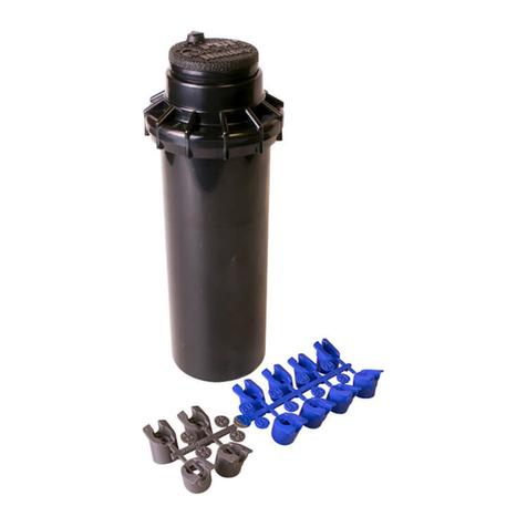
Additional “Specialty Use” I-20 nozzles
are available from authorized Hunter
Distributors. They include a short radius
nozzle rack (p/n 466100) which has
nozzles for use in the 18'-25' range.
There is also a high flow nozzle rack
available (p/n 444800) which has
nozzles that have larger flows, both in
standard and low angle configurations.
Performance information can be found
in the Hunter products catalog.
