Minix 890GX User manual

Rev: 1.00, Aug 2010
User's Manual
MINIXTM 890GX/880G-USB3
Website: http://www.jwele.com
Mini-ITX Motherboard

Disclaimer
The intellectual property of this manual belongs to our company. The ownership of all of the
products, including accessories and software etc. belong to our company. No one is permitted to
copy, change, or translate without our written permission.
We compiled this manual based on our careful attitude, but we can not guarantee the accuracy of
the contents. This manual is purely technical documentation, without any hint or other meanings,
and we won't commit users' misunderstanding of the typesetting error.
Our products are in continuous improvement and updating, Therefore, we retain the right that we
won't give notice to the users in future.
Copyright
All of the trademark in this manual belong to their own registered company.
All of the products name is only for identification, its title belongs to its manufacturer or brand
owner.

Table of Contents
Chapter 1 Introduction ............................................................................................ 4
1.1 Package Checklist ................................................................................................................4
1.2 Specications ......................................................................................................................5
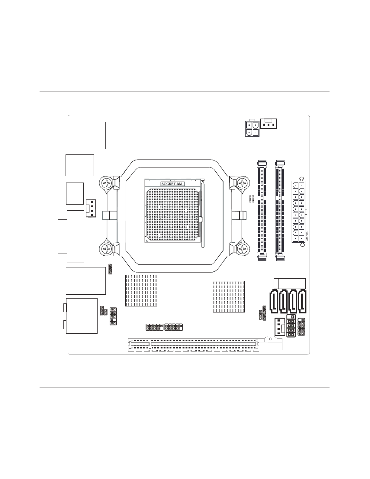
1.3 Mainboard Layout................................................................................................................6
1.4 Connecting Rear Panel I/O Devices .......................................................................................7
Chapter 2 Hardware Setup....................................................................................... 8
2.1 Choosing a Computer Chassis...............................................................................................8
2.2 Installing Mainboard ............................................................................................................8
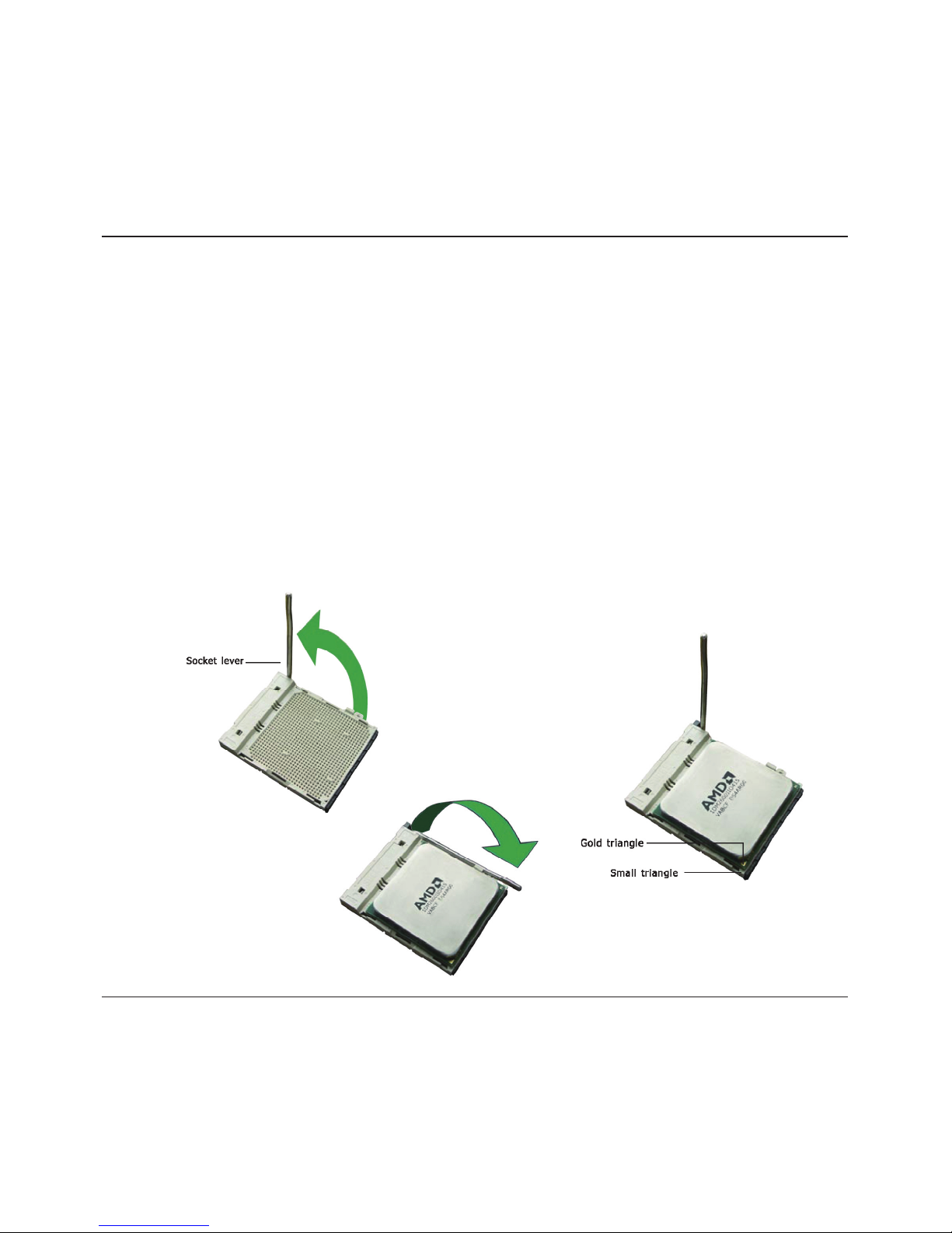
2.3 Installing CPU and CPU Cooler...............................................................................................9
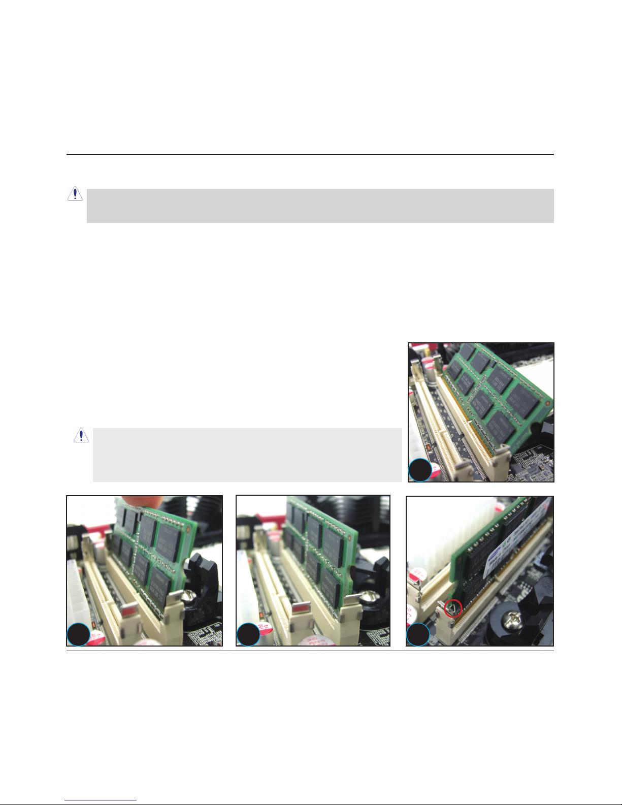
2.4 Installation of Memory Modules .......................................................................................... 10
2.5 Connecting Peripheral Devices ............................................................................................ 11
2.5.1 Serial ATA Connectors .................................................................................................. 11
2.5.2 PCIE slot.....................................................................................................................11
2.5.3 MINIPCIE slot...............................................................................................................11
2.5.4 Guide for installing the antennas of the Wi-Bluetooth moudle(optional)..........................12
Chapter 3 Jumpers & Headers Setup .......................................................................14
Chapter 4 BIOS Setup Utility ...................................................................................19
4.1 About BIOS Setup.............................................................................................................. 19
4.2 To Run BIOS Setup ............................................................................................................ 19
4.3 About CMOS...................................................................................................................... 19
4.4 The POST (Power On Self Test) .......................................................................................... 19
4.5 BIOS Setup — CMOS Setup Utility....................................................................................... 20
4.5.1 CMOS Setup Utility....................................................................................................... 20
4.5.2 Control Keys................................................................................................................ 21
4.5.3 Main Menu .................................................................................................................. 22
4.5.4 Advanced Setting.........................................................................................................25
4.5.5 Boot Setting ................................................................................................................ 31
4.5.6 Security Setting ........................................................................................................... 33
4.5.7 Power Setting .............................................................................................................. 35
4.5.8 PC&Health................................................................................................................... 35
4.5.9 Exit Setting ................................................................................................................. 40
Chapter 5 Driver Installation ...................................................................................44

MINIX 890GX/880G-USB3 User's Manual
- 4 -
Chapter 1 Introduction
1.1 Package Checklist
Thank you for choosing our product.
Please check the following packing and accessories, if there is any broken or part missing,
please contact with your franchiser.
• Rear I/O Panel X 1
• User's Manual X 1
• Driver/Utility DVD X 1
• Serial ATA Signal Cable X 2
• Serial ATA Power Cable X 2
• Antenna Kit X 2 (optional)
The items listed above are for reference only, and are subject to change without notice.

MINIX 890GX/880G-USB3 User's Manual
- 5 -
1.2 Specications
CPU
- Support AMD(R) Socket AM3 processors
- AMD Phenom™ II x4/ Phenom™ II x3/ Phenom™ II x2/ Athlon™ II x4/
Athlon™II x3/Athlon™ II x2/ Sempron™ 1xx processors
Main Chipset/
Integrated Graphics
- 890GX+SB850(Optional)
- Radeon HD 4290
- 880G+SB850(Optional)
- Radeon HD 4250
Main Memory - Support 2x1.5V DDR3 SODIMM sockets supporting up to 8GB memory
- Support for DDR3 1066/1333MHz memory modules
BIOS
- AMI BIOS, supports Plug&Play
- Supports Advanced Power Management ACPI,STR
- CPU temperature, Fan speed, System Voltage monitoring
Rear Panel I/O
- 2 x USB3.0 ports
- 1 x HDMI port
- 1 x VGA port
- 1 x DVI port
- 1 x SPDIF_OUT port
- 2 x RJ45 ports
- 4 x USB 2.0 ports
- 5 x Audio ports (Line In / Line Out / MIC In/ Rear Speaker Out / Center-
Subwoofer Speaker Out )
Internal I/O
Connectors
- 1 x 20-pin ATX main power connector
- 1 x 4-pin ATX 12V power connector
- 4 x SATA 6Gb/s connectors
- 2 x System fan headers
- 1 x CPU FAN header
- 1 x Front panel header
- 1 x Front panel audio header
- 1 x SPDIF_OUT header
- 1 x SPDIF_IN header(Optional)
- 1 x COM header
- 1 x SPEAK header
- 2 x USB 2.0 headers for additional 4 USB 2.0 ports (by cables)
Sound - Onboard 8-channel HD Audio Codec
- Front Panel Jumper, provides stereo MIC port on front panel
Onboard LAN - Onboard 10/100/1000Mbps compatible LAN (Optional)
Expansion Slots - 1 x PCIE slot
- 1 x MINIPCIE slot
Form Factor Mini ITX (170mm*170mm)

MINIX 890GX/880G-USB3 User's Manual
- 6 -
1.3 Mainboard Layout
(This picture is only for reference)
PCIE1
F AU DIO_
JSPDIF
SPEAK
JB AT SATA1
SATA2
FUSB1 FUSB2
SFA N2
PWR12V
CFA N
SATA3
SATA4
3
B T1
JCOM
JHPD
SFAN1
USBLAN1
USB1
HDMI
DVI-VGA
USBLAN2
AUDIO
JRS890ITX V1 0
170 170MM
.
*
FPANEL

MINIX 890GX/880G-USB3 User's Manual
- 7 -
1.4 Connecting Rear Panel I/O Devices
The rear I/O part of these mainboard provides the following I/O ports:
(This picture is only for reference)
• USB3.0: Connects to USB3.0 devices.
• HDMI:Connects to multimedia devices of HDMI protocol.
• VGA: Connects to a monitor's VGA input.
• DVI: Connects to monitor input.
• SPDIF OUT: Connects to digital audio device.
• USB: The USB ports are used to connect USB 2.0/1.1 devices such as scanner, speakers,
keyboard, mouse, hub, digital camera, joystick, etc.
• LAN: The LAN port allows the motherboard to connect to a local area network by means of
a network hub.
• AUDIO(Rear Panel Audio):
Cen./Sub. (Center / Subwoofer): Connects to the center and subwoofer channel in the 7.1
channel audio system.
R.L./R.R. (Rear Left / Rear Right): Connects to the rear left and rear right channel in the 7.1
channel audio system.
Line-in (Light Blue): This jack is used to connect to the line out from any external audio
sources such as MP3 player, CD player, AM/FM radio tuner, etc.
ine-out (Front Left/Right Jack, Lime): This jack is used to connect to the front left and
right channel speakers of the audio system.
Mic-in (Pink): This jack is used to connect an external microphone.
USB3 0.
SPDIF 0UT_

MINIX 890GX/880G-USB3 User's Manual
- 8 -
Chapter 2 Hardware Setup
2.1 Choosing a Computer Chassis
• Choose a chassis big enough to install this mainboard.
• As some features for this mainboard are implemented by cabling connectors on the
mainboard
to indicators and switches or buttons on the chassis, make sure your chassis supports all the
features required.
• If there is possibility of adopting some more hard drives, make sure your chassis has sufcient
power and space for them.
• Most chassis have alternatives for I/O shield located at the rear panel. Make sure the I/O
shield
of the chassis matches the I/O port conguration of this mainboard. You can nd
an I/O shield
specically designed for this mainboard in its package.
2.2 Installing Mainboard
Most computer chassis have a base with many mounting holes to allow the mainboard to be
securely attached, and at the same time, prevent
the system from short circuits. There are two ways
to attach the mainboard to the chassis base:
(1)with studs, or (2) with spacers.
Basically, the best way to attach the board is with
studs. Only if you are unable to do this should you
attach the board with spacers. Line up the holes on
the board with the mounting holes on the chassis.
If the holes line up and there are screw holes, you
can attach the board with studs. If the holes line
up and there are only slots, you can only attach with
spacers. Take the tip of the spacers and insert them into the slots. After doing this to all the slots,
you can slide the board into position aligned with slots. After the board has been positioned,
check to make sure everything is OK before putting the chassis back on.
To install this mainboard:
1. Locate all the screw holes on the mainboard and the chassis base.
2. Place all the studs or spacers needed on the chassis base and have them tightened.
3. Face the mainboard’s I/O ports toward the chassis’s rear panel.
4. Line up all the mainboard’s screw holes with those studs or spacers on the chassis.
5. Install the mainboard with screws and have them tightened.

MINIX 890GX/880G-USB3 User's Manual
- 9 -
2.3 Installation of the CPU and CPU Cooler
Before installing the CPU, please comply with the following conditions:
1. Please make sure that the mainboard supports the CPU.
2. Please take note of the one indented corner of the CPU. If you install the CPU in the wrong
direction, the CPU will not insert properly. If this occurs, please change the insert direction of
the CPU.
3. Please add an even layer of heat sink paste between the CPU and CPU cooler.
4. Please make sure the CPU cooler is installed on the CPU prior to system use, otherwise
overheating and permanent damage of the CPU may occur.
5. Please set the CPU host frequency in accordance with the processor specications. It is not
recommended that the system bus frequency be set beyond hardware specications since it
does not meet the required standards for the peripherals. If you wish to set the frequency
beyond the proper specications, please do so according to your hardware specications
including the CPU, graphics card, memory, hard drive, etc.
2.3.1 Installation of the CPU
1. Unlock the socket by pressing the
lever sideways, then lift it up to a 90
o
.
2. Position the CPU above the socket such that
the CPU corner with the gold triangle matches
the socket corner with a small triangle.
3. Carefully insert the CPU into the socket until it
ts place.
4. When the CPU is in
place, push down the
socket lever to secure
the CPU.
The lever clicks on the
side tab to indicate that
it is locked.
Figure 1
Figure 2
Figure 3

MINIX 890GX/880G-USB3 User's Manual
- 10 -
2.3.2 Installation of the CPU Cooler
For proper installation, please kindly refer to the instruction manuals of your CPU Cooler.
2.4 Installation of Memory Modules
This mainboard provides two 204-pin DDRIII (Double Data Rate) SODIMM slots and supports
Dual Channel Memory Technology. For dual channel conguration, you always need to install two
identical (the same brand, speed, size and chip-type) memory modules in the DDRIII DIMM slots
to activate Dual Channel Memory Technology. Otherwise, it will operate at single channel mode.
To install system memory:
1. Power off the computer and unplug the AC power cord before
installing or removing memory modules.
2. Locate the DIMM slot on the board.
3. Insert the SODIMM module at a 45 degree angle.
4. Push the SODIMM module back towards theboard until the clips
lock the module in place.
5. To remove the DIMM modules, push the two ejector tabs on the
slot outward simultaneously, and then pull out the DIMM module.
Static electricity can damage the electronic components of the
computer or optional boards. Before starting these procedures,
ensure that you are discharged of static electricity by touching
a grounded metal object briey.
We suggest there should be active cooling to the chipset area in order to let the motherboard
function properly, completely enclosed system environment without adequate air ow will result
in chipset overheat, which is not recommended.
1
2 3 4

MINIX 890GX/880G-USB3 User's Manual
- 11 -
2.5 Connecting Peripheral Devices
2.5.1 Serial ATA Connectors
Each SATA connector serves as one single channel to connect one SATA device by SATA cable.
2.5.2 PCIE slot
Install PCIE card into slot “PCIE1” .
PCIE1
F AUD IO_
JSPDIF
SPEAK
JBAT S ATA1
SATA2
FUSB1 FUSB2
SFAN 2
PWR12V
CFAN
SATA3
SATA4
3
B T1
JCOM
JHPD
SFA N1
USBLAN1
US B1
HD MI
DVI-VGA
USBLAN2
AU DI O
JRS890ITXV1 0
170 170MM
.
*
FPANEL
2.5.3 MINIPCIE slot
Install Wireless,3G,Bluetooth card into slot “MINIPCIE1” .
This slot at the motherboard's reverse side.

MINIX 890GX/880G-USB3 User's Manual
- 12 -
2.5.4 Guide for installing the antennas of the Wi-Bluetooth module(optional)
1.) Locate the Wi-Bluetooth combo
mini card at the bottom side of the
motherboard. Identify the 2 connectors
for the antennas, please note that
ANT1 is assigned for Wifi and ANT2
is assigned for Bluetooth, you MUST
conne c t both con n ectors t o t he
antennas in order to enjoy full function
of the card.
2.) Gently plu g i n t he wi r e s of
antennas onto both connectors of the
Wifi-Bluetooth combo mini card, you
will hear a “click” sound when they are
installed and locked properly.
3.) Identify the notch on the edge of
the PCB at the side of the rear I/O
panel; this notch is designed to let the
antennas to go through to the top side
of the motherboard.
4.) Route both antennas through the
notch as illustrated in the picture.
5.) Identify the mounting holes on the
I/O shield for the 2 antennas, ANT.1 for
Wifi antenna and ANT.2 for Bluetooth
antenna.
6.) Unscrew the nuts off the bolts of
both antennas, while keeping the rings
of both antennas adhered.
12
34
56

MINIX 890GX/880G-USB3 User's Manual
- 13 -
7.) After you have installed the
motherboard and the I/O shield into
the computer case, you could start
mounting the antennas onto the I/O
shield, keep the ring of both antennas
within the side of the computer case
and let the studs to go through the
I/O shield to outside of the computer
case.
8.) Now screw both nuts back to the
bolts of the antennas clock-wisely
until they are tight enough to hold the
antennas in position.
9.) Screw both antennas onto the
studs clock-wisely until they are tight
enough to hold themselves in position.
10.) Adjust the angle of the antennas,
and n ow y ou h ave f inished the
antenna installation.
7 8
910

MINIX 890GX/880G-USB3 User's Manual
- 14 -
Chapter 3 Jumpers & Headers Setup
Quick Components Guide
NO. Layout Page NO. No. Layout Page NO.
1F_AUDIO 13 8BT1 15
2FUSB1/FUSB2 13 9 ATXPWR 15
3JBAT 14 10 SFAN2 14
4 SPEAK 14 11 PWR12V 15
5SFAN1 14 12 CFAN 16
6 JCOM 15 13 JHPD 16
7FPANEL 14 14 JSPDIF 16
PCIE1
F AUD IO_
JSPDIF
SPEAK
JBATSATA1
SATA2
FUSB1 FUSB2
SFAN 2
PWR12V
CFAN
SATA3
SATA4
3
B T1
JCOM
JHPD
SFA N1
USBLAN1
US B1
HD MI
DVI-VGA
USBLAN2
AU DIO
JRS890ITXV1 0
170 170MM
.
*
FPANEL
1 2 345 6 7
8
9
10
11
12
13
14

MINIX 890GX/880G-USB3 User's Manual
- 15 -
Checking Jumper Settings
• For a 2-pin jumper, plug the jumper cap on both pins will make it CLOSE (SHORT). Remove the
jumper cap, or plug it on either pin (reserved for future use) will leave it at OPEN position.
• For 3-pin jumper, pin 1~2 or pin 2~3 can be shorted by plugging the jumper cap in.
How to identify the PIN1 jumpers?
Please check the mainboard carefully, the PIN1 is marked by "1" or white thick line.
1-F_AUDIO(Front Panel Audio Connection Header)
Pin No. Header HD Audio Denition AC97 Audio Denition
1 PORT1L Microphone_Left Microphone
2 AGND Ground Ground
3 PORT1R Microphone_Right MIC Power
4 PRESENCE# -ACZ_DET N/A
5 PORT2R Line2_Right Line out (R)
6 SENSE1_RETURN AuD_R_Return N/A
7 SENSE_SEND FAUDIO_JD N/A
8 No Pin N/A N/A
9 PORT2L Line2_Left Line Out(L)
10 SENSE2_RETURN AuD_L_Return N/A
2-FUSB1/FUSB2(Additional USB Port Headers)
Pin No. Denition Pin No. Denition
1 VCC 2 VCC
3Data 0- 4Data 1-
5Data 0+ 6Data 1+
7 Ground 8 Ground
10 NC

MINIX 890GX/880G-USB3 User's Manual
- 16 -
4/7-SPEAK/FPANEL(Speaker Headers & Front Panel Switches)
HD_LED (Red): Hard Driver LED connector
This connector connects to the case-mounted
HD LED cable, and the LED will light when the
hard drive(s) is/are being accessed.
RST (Blue): Reset Switch
This connector connects to the case-mounted
reset switch which allows you to reboot without
having to power-off the system and thus prolonging the life of the power supply or system.
PWR_ON (Black): Power Switch
Depending on the setting in the BIOS setup, this switch serves two functions which will allow
you to power-on/off the system or to enter the suspend mode.
PWR_LED (Green): Power/Standby LED
When the system's power is on, this LED will light. When the system is in the S1 (POS - Power
on Suspend) or S3 (STR - Suspend to RAM, optional) state, it will blink every second.
SPEAKER (Yellow or Black): Speaker Connector
This 4-pin connector connects to the case-mounted speaker.
SPEAK:
Pin No. Denition
1SPK +
2 NC
3 NC
4SPK -
3-JBAT(CMOS Memory Clearing Header)
The time to clear the CMOS memory occurs when (a) the CMOS data becomes corrupted, (b)
you forgot the supervisor or user password preset in the BIOS menu, (c) you are unable to
boot-up the system because the CPU ratio/clock was incorrectly set in the BIOS menu, or (d)
whenever there is modication on the CPU or memory modules.
This header uses a jumper cap to clear the CMOS
memory and have it recongured to the default values
stored in BIOS.
• Pins 1 and 2 shorted (Default): Normal operation.
• Pins 2 and 3 shorted: Clear CMOS memory.
+-
+-
PWR LED_PWR ON_
HD LED_RST
5/10-SFAN1/SFAN2(Fan Power Connectors Header)
SFAN2:System fan connectors
Pin No. Denition
1 GND
2+12V
3 RPM
These fan connectors are not jumpers.
DO NOT place jumper caps on these
connectors.
SFAN1:System fan connectors
Pin No. Denition
1 GND
2+12V
3 RPM
4 Control

MINIX 890GX/880G-USB3 User's Manual
- 17 -
34
GND GND
+12V
+12V
1 2
PWR12V
9/11- ATX Power Input Connectors
ATXPWR (ATX Power) connector
We recommend to use our motherboard with a power supply that complies with the ATX12V
Power Supply Design Guide Version 1.1. Every ATX12V power supply unit has a standard
24-pin ATX main power connector that must be plugged into this connector. If you would like
to use an old power supply with only a 20-pin ATX main power connector, then please plug
the 20-pin ATX main power connector along with pin 1 and pin 13.
PWR12V (+12V Power) connector
Your power supply unit may come with a 4-pin or 8-pin +12V power connector. The +12V
power enables the delivery of more +12VDC current to the CPU's Voltage Regulator Module
(VRM). If available, please use the 8-pin power; otherwise please connect the 4-pin power
to this connector.
113
10 20
+ .3 3V
+5V
GND
PWRGD
PS ON-
N C/
+ .3 3V
GND
+12V
+5V
GND
+5VSB
+ .3 3V
-12V
GND
GND
GND
GND
+5V
+5V
ATXPWR
6-JCOM1(Serial Port Header)
This JCOM1 header supports a serial port module.
Pin No. Denition Pin No. Denition
1 DCD 2 RXD
3 TXD 4 DTR
5 GND 6 DSR
7 RTS 8 CTS
9 RI
8- BT1(Battery)
Install the motherboard battery.

MINIX 890GX/880G-USB3 User's Manual
- 18 -
13-JHPD
12-CFAN(CPU Fan Power Connectors Header)
These fan connectors are not jumpers.
DO NOT place jumper caps on these
connectors.
CFAN:CPU fan connectors
Pin No. Denition
1 GND
2+12V
3 RPM
4 Control
14-S/PDIF Output Connection Header
S/PDIF (Sony/Philips Digital Interface) is a standard audio transfer
le format. It is usually found on digital audio equipment such as a
DAT (Digital Audio Tape) machine or audio processing device. It
allows the transfer of audio from one le to another without the
conversion to and from an analog format, which could degrade the
signal quality.
While the JHPD jumper are shorted at pin 1-2, the motherboard will automatically detect any DVI or HDMI display
device; if the DVI or HDMI device cannot be detected, please short these jumpers to pin 2-3 to enable force DVI/
HDMI device detection.
Pin No. Denition
Pin1-2 Auto
Pin2-3 HDMI/DVI EN
2
5
1
VCC
OUT
GND
IN
NC

MINIX 890GX/880G-USB3 User's Manual
- 19 -
Chapter 4 BIOS Setup Utility
BIOS stands for Basic Input and Output System. It was once called ROM BIOS when it was stored
in a Read-Only Memory (ROM) chip. Now manufacturers would like to store BIOS in EEPROM which
means Electrically Erasable Programmable Memory. BIOS used in this series of mainboard is stored
in EEPROM, and is the rst program to run when you turn on your computer.
BIOS performs the following functions:
1. Initializing and testing hardware in your computer (a process called "POST", for Power On Self
Test).
2. Loading and running your operating system.
3. Helping your operating system and application programs manage your PC hardware by means of
a set of routines called BIOS Run-Time Service.
4.1 About BIOS Setup
BIOS Setup is an interactive BIOS program that you need to run when:
1. Changing the hardware of your system. (For example: installing a new Hard Disk etc.)
2. Modifying the behavior of your computer. (For example: changing the system time or date, or
turning special features on or off etc.)
3. Enhancing your computer's behavior. (For example: speeding up performance by turning on
shadowing or cache)
4.2 To Run BIOS Setup
First access BIOS setup menu by pressing <F1> key after “POST” is complete (before OS is
loaded). After the rst BIOS be setupped(or loaded default values) and save, the <DEL> key will
be pressed if you will enter BIOS setup menu.
4.3 About CMOS
CMOS is the memory maintained by a battery. CMOS is used to store the BIOS settings you have
selected in BIOS Setup. CMOS also maintains the internal clock. Every time you turn on your
computer, the BIOS Looks into CMOS for the settings you have selected and congures your
computer accordingly. If the battery runs out of power, the CMOS data will be lost and POST will
issue a “CMOS invalid” or “CMOS checksum invalid” message. If this happens, you have to replace
the battery and check and congure the BIOS Setup for the new start.
4.4 The POST (Power On Self Test)
POST is an acronym for Power On Self Test. This program will test all things the BIOS does

MINIX 890GX/880G-USB3 User's Manual
- 20 -
before the operating system is started. Each of POST routines is assigned a POST code, a unique
number which is sent to I/O port 080h before the routine is executed.
4.5 BIOS Setup — CMOS Setup Utility
4.5.1 CMOS Setup Utility
After powering up the system, the BIOS message appears on the screen,when the rst time or
when CMOS setting wrong, there is following message appears on the screen , but if the rst
rst BIOS be setuped(or loaded default values) and save, the <DEL> key will be pressed if you
will enter BIOS setup menu.
If this message disappears before you respond, restart the system by pressing <Ctrl> + <Alt>+
<Del> keys, or by pressing the reset button on computer chassis. Only when these two methods
should be fail that you restart the system by powering it off and then back on.
After pressing <F1> or <Del> key, the main menu appears.
Press F1 to Run SETUP
• In order to increase system stability and performance, our engineering staff is constantly
improving the BIOS menu. The BIOS setup screens and descriptions illustrated in this manual
are for your reference only, and may not completely match with what you see on your screen.
• Do not change the BIOS parameters unless you fully understand its function.
BIOS SETUP UTILITY
Main Advanced Boot Security JUSTw00t! Power Exit
System Overview
←
Select Screen
↑↓
Select Item
Enter Go to Sub Screen
F1 General Help
F10 Save and Exit
ESC Exit
►
System Information
System Time
System Date
Language
Floppy A
Power on Beep
[22:15:32]
[Thu 06/19/2008]
[English]
[1.44 MB 3
1/2
"]
[Enabled]
►
SATA 1
►
SATA 2
►
SATA 3
►
SATA 4
: [Not Detected]
: [Not Detected]
: [Hard Disk]
: [Not Detected]
v02.61 (C)Copyright 1985-2006, American Megatrends, Inc.
Other manuals for 890GX
1
This manual suits for next models
1
Table of contents
Other Minix Motherboard manuals