Minix 890GX User manual

Rev: 1.00, Aug 2010
User's Manual
MINIXTM 890GX/880G-USB3
Website: http://www.jwele.com
Mini-ITX Motherboard

Disclaimer
The intellectual property of this manual belongs to our company. The ownership of all of the
products, including accessories and software etc. belong to our company. No one is permitted to
copy, change, or translate without our written permission.
We compiled this manual based on our careful attitude, but we can not guarantee the accuracy of
the contents. This manual is purely technical documentation, without any hint or other meanings,
and we won't commit users' misunderstanding of the typesetting error.
Our products are in continuous improvement and updating, Therefore, we retain the right that we
won't give notice to the users in future.
Copyright
All of the trademark in this manual belong to their own registered company.
All of the products name is only for identification, its title belongs to its manufacturer or brand
owner.

Table of Contents
Chapter 1 Introduction ............................................................................................ 4
1.1 Package Checklist ................................................................................................................4
6SHFL¿FDWLRQV ......................................................................................................................5
1.3 Mainboard Layout................................................................................................................6
1.4 Connecting Rear Panel I/O Devices .......................................................................................7
Chapter 2 Hardware Setup....................................................................................... 8
2.1 Choosing a Computer Chassis...............................................................................................8
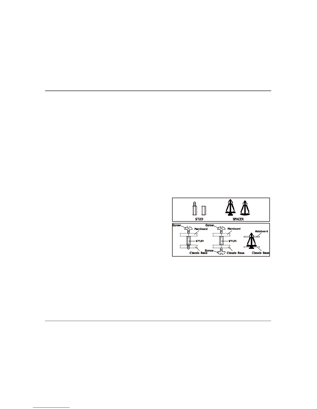
2.2 Installing Mainboard ............................................................................................................8
2.3 Installing CPU and CPU Cooler...............................................................................................9
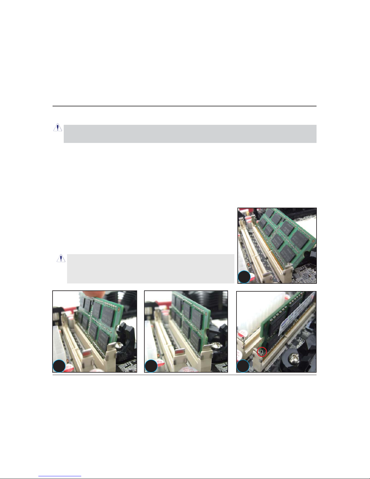
2.4 Installation of Memory Modules .......................................................................................... 10
2.5 Connecting Peripheral Devices ............................................................................................ 11
2.5.1 Serial ATA Connectors .................................................................................................. 11
2.5.2 PCIE slot..................................................................................................................... 11
2.5.3 MINIPCIE slot...............................................................................................................11
*XLGHIRULQVWDOOLQJWKHDQWHQQDVRIWKH:L¿%OXHWRRWKPRXGOHRSWLRQDO
Chapter 3 Jumpers & Headers Setup .......................................................................14
&KDSWHU%,266HWXS8WLOLW\ ...................................................................................19
$ERXW%,266HWXS.............................................................................................................. 19
7R5XQ%,266HWXS ............................................................................................................ 19
4.3 About CMOS...................................................................................................................... 19
7KH32673RZHU2Q6HOI7HVW .......................................................................................... 19
%,266HWXS²&0266HWXS8WLOLW\....................................................................................... 20
4.5.1 CMOS Setup Utility....................................................................................................... 20
4.5.2 Control Keys................................................................................................................ 21
4.5.3 Main Menu ..................................................................................................................22
4.5.4 Advanced Setting......................................................................................................... 25
%RRW6HWWLQJ ................................................................................................................ 31
4.5.6 Security Setting ........................................................................................................... 33
4.5.7 Power Setting .............................................................................................................. 35
4.5.8 PC&Health................................................................................................................... 35
4.5.9 Exit Setting ................................................................................................................. 40
Chapter 5 Driver Installation ...................................................................................44

MINIX *;*86% User's Manual
- 4 -
Chapter 1 Introduction
1.1 Package Checklist
Thank you for choosing our product.
Please check the following packing and accessories, if there is any broken or part missing,
please contact with your franchiser.
• Rear I/O Panel X 1
• User's Manual X 1
• Driver/Utility DVD X 1
• Serial ATA Signal Cable X 2
• Serial ATA Power Cable X 2
$QWHQQD.LW;RSWLRQDO
The items listed above are for reference only, and are subject to change without notice.

MINIX *;*86% User's Manual
- 5 -
6SHFL¿FDWLRQV
CPU
6XSSRUW$0'56RFNHW$0SURFHVVRUV
$0'4200+ 2.8GHz
Main Chipset/
Integrated Graphics
5DGHRQ+'
5DGHRQ+'
Main Memory 6XSSRUW*%PHPRU\
6XSSRUWIRU''528PHPRU\PRGXOHV
%,26
$0,%,26VXSSRUWV3OXJ3OD\
6XSSRUWV$GYDQFHG3RZHU0DQDJHPHQW$&3,675
&38WHPSHUDWXUH)DQVSHHG6\VWHP9ROWDJHPRQLWRULQJ
Rear Panel I/O
2[86%SRUWV
[+'0,SRUW
[9*$SRUW
['9,SRUW
[5-SRUWV
[86%SRUWV
3[$XGLRSRUWV0,&,Q5HDU6SHDNHU2XW&HQWHU
6XEZRRIHU6SHDNHU2XW
Internal I/O
Connectors
[SLQ$7;PDLQSRZHUFRQQHFWRU
[SLQ$7;9SRZHUFRQQHFWRU
[6$7$*EVFRQQHFWRUV
[6\VWHPIDQKHDGHUV
[&38)$1KHDGHU
[)URQWSDQHOKHDGHU
[)URQWSDQHODXGLRKHDGHU
[63',)B287KHDGHU
[63',)B,1KHDGHU2SWLRQDO
[&20KHDGHU
[63($.KHDGHU
[86%KHDGHUVIRUDGGLWLRQDO86%SRUWVE\FDEOHV
Sound 2QERDUG2FKDQQHO+'$XGLR&RGHF
)URQW3DQHO-XPSHUSURYLGHVVWHUHR0,&SRUWRQIURQWSDQHO
Onboard LAN 2QERDUG0ESVFRPSDWLEOH/$12SWLRQDO
Expansion Slots [3&,(VORW
[0,1,3&,(VORW
)RUP)DFWRU 0LQL,7;PPPP

MINIX *;*86% User's Manual
- 6 -
1.3 Mainboard Layout
7KLVSLFWXUHLVRQO\IRUUHIHUHQFH
!

MINIX *;*86% User's Manual
- 7 -
1.4 Connecting Rear Panel I/O Devices
The rear I/O part of these mainboard provides the following I/O ports:
7KLVSLFWXUHLVRQO\IRUUHIHUHQFH
86%&RQQHFWVWR86%devices.
• HDMI:Connects to multimedia devices of HDMI protocol.
• VGA: Connects to a monitor's VGA input.
• DVI: Connects to monitor input.
63',)287&RQQHFWVWRGLJLWDODXGLRGHYLFH
86%7KH86%SRUWVDUHXVHGWRFRQQHFW86%GHYLFHVVXFKDVVFDQQHUVSHDNHUV
keyboard, mouse, hub, digital camera, joystick, etc.
• LAN: The LAN port allows the motherboard to connect to a local area network by means of
a network hub.
$8',25HDU3DQHO$XGLR
&HQ6XE&HQWHU6XEZRRIHU&RQQHFWVWRWKHFHQWHUDQGVXEZRRIHUFKDQQHOLQWKH
channel audio system.
5/555HDU/HIW5HDU5LJKW&RQQHFWVWRWKHUHDUOHIWDQGUHDUULJKWFKDQQHOLQWKH
channel audio system.
/LQHLQ/LJKW%OXH7KLVMDFNLVXVHGWRFRQQHFWWRWKHOLQHRXWIURPDQ\H[WHUQDODXGLR
VRXUFHVVXFKDV03SOD\HU&'SOD\HU$0)0UDGLRWXQHUHWF
LQHRXW)URQW/HIW5LJKW-DFN/LPH7KLVMDFNLVXVHGWRFRQQHFWWRWKHIURQWOHIWDQG
right channel speakers of the audio system.
0LFLQ3LQN7KLVMDFNLVXVHGWRFRQQHFWDQH[WHUQDOPLFURSKRQH

MINIX *;*86% User's Manual
- 8 -
Chapter 2 Hardware Setup
2.1 Choosing a Computer Chassis
• Choose a chassis big enough to install this mainboard.
• As some features for this mainboard are implemented by cabling connectors on the mainboard
to indicators and switches or buttons on the chassis, make sure your chassis supports all the
features required.
,IWKHUHLVSRVVLELOLW\RIDGRSWLQJVRPHPRUHKDUGGULYHVPDNHVXUH\RXUFKDVVLVKDVVXI¿FLHQW
power and space for them.
• Most chassis have alternatives for I/O shield located at the rear panel. Make sure the I/O shield
RIWKHFKDVVLVPDWFKHVWKH,2SRUWFRQ¿JXUDWLRQRIWKLVPDLQERDUG<RXFDQ¿QG an I/O shield
VSHFL¿FDOO\GHVLJQHGIRUWKLVPDLQERDUGLQLWVSDFNDJH
2.2 Installing Mainboard
Most computer chassis have a base with many mounting holes to allow the mainboard to be
securely attached, and at the same time, prevent
the system from short circuits. There are two ways
to attach the mainboard to the chassis base:
ZLWKVWXGVRUZLWKVSDFHUV
%DVLFDOO\WKHEHVWZD\WRDWWDFKWKHERDUGLVZLWK
studs. Only if you are unable to do this should you
attach the board with spacers. Line up the holes on
the board with the mounting holes on the chassis.
If the holes line up and there are screw holes, you
can attach the board with studs. If the holes line
up and there are only slots, you can only attach with
spacers. Take the tip of the spacers and insert them into the slots. After doing this to all the slots,
you can slide the board into position aligned with slots. After the board has been positioned,
check to make sure everything is OK before putting the chassis back on.
To install this mainboard:
1. Locate all the screw holes on the mainboard and the chassis base.
2. Place all the studs or spacers needed on the chassis base and have them tightened.
)DFHWKHPDLQERDUG¶V,2SRUWVWRZDUGWKHFKDVVLV¶VUHDUSDQHO
/LQHXSDOOWKHPDLQERDUG¶VVFUHZKROHVZLWKWKRVHVWXGVRUVSDFHUVRQWKHFKDVVLV
5. Install the mainboard with screws and have them tightened.

MINIX *;*86% User's Manual
- 9 -
2.3 Installation of the CPU and CPU Cooler
%HIRUHLQVWDOOLQJWKH&38SOHDVHFRPSO\ZLWKWKHIROORZLQJFRQGLWLRQV
1. Please make sure that the mainboard supports the CPU.
2. Please take note of the one indented corner of the CPU. If you install the CPU in the wrong
direction, the CPU will not insert properly. If this occurs, please change the insert direction of
the CPU.
3. Please add an even layer of heat sink paste between the CPU and CPU cooler.
4. Please make sure the CPU cooler is installed on the CPU prior to system use, otherwise
overheating and permanent damage of the CPU may occur.
3OHDVHVHWWKH&38KRVWIUHTXHQF\LQDFFRUGDQFHZLWKWKHSURFHVVRUVSHFL¿FDWLRQV,WLVQRW
UHFRPPHQGHGWKDWWKHV\VWHPEXVIUHTXHQF\EHVHWEH\RQGKDUGZDUHVSHFL¿FDWLRQVVLQFHLW
does not meet the required standards for the peripherals. If you wish to set the frequency
EH\RQGWKHSURSHUVSHFL¿FDWLRQVSOHDVHGRVRDFFRUGLQJWR\RXUKDUGZDUHVSHFL¿FDWLRQV
including the CPU, graphics card, memory, hard drive, etc.
2.3.1 Installation of the CPU
1. Unlock the socket by pressing the
lever sideways, then lift it up to a 90
o
.
2. Position the CPU above the socket such that
the CPU corner with the gold triangle matches
the socket corner with a small triangle.
3. Carefully insert the CPU into the socket until it
¿WVSODFH
4. When the CPU is in
place, push down the
socket lever to secure
the CPU.
The lever clicks on the
side tab to indicate that
it is locked.
Figure 1
Figure 2
Figure 3

MINIX *;*86% User's Manual
- 10 -
2.3.2 Installation of the CPU Cooler
)RUSURSHULQVWDOODWLRQSOHDVHNLQGO\UHIHUWRWKHLQVWUXFWLRQPDQXDOVRI\RXU&38&RROHU
2.4 Installation of Memory Modules
7KLVPDLQERDUGSURYLGHVWZRSLQ''5,,,'RXEOH'DWD5DWH62',00VORWVDQGVXSSRUWV
'XDO&KDQQHO0HPRU\7HFKQRORJ\)RUGXDOFKDQQHOFRQ¿JXUDWLRQ\RXDOZD\VQHHGWRLQVWDOOWZR
LGHQWLFDOWKHVDPHEUDQGVSHHGVL]HDQGFKLSW\SHPHPRU\PRGXOHVLQWKH''5,,,',00VORWV
to activate Dual Channel Memory Technology. Otherwise, it will operate at single channel mode.
To install system memory:
1. Power off the computer and unplug the AC power cord before
installing or removing memory modules.
2. Locate the DIMM slot on the board.
3. Insert the SODIMM module at a 45 degree angle.
4. Push the SODIMM module back towards theboard until the clips
lock the module in place.
5. To remove the DIMM modules, push the two ejector tabs on the
slot outward simultaneously, and then pull out the DIMM module.
Static electricity can damage the electronic components of the
FRPSXWHURURSWLRQDOERDUGV%HIRUHVWDUWLQJWKHVHSURFHGXUHV
ensure that you are discharged of static electricity by touching
DJURXQGHGPHWDOREMHFWEULHÀ\
We suggest there should be active cooling to the chipset area in order to let the motherboard
IXQFWLRQSURSHUO\FRPSOHWHO\HQFORVHGV\VWHPHQYLURQPHQWZLWKRXWDGHTXDWHDLUÀRZZLOOUHVXOW
in chipset overheat, which is not recommended.
1
2 3 4

MINIX *;*86% User's Manual
- 11 -
2.5 Connecting Peripheral Devices
2.5.1 Serial ATA Connectors
Each SATA connector serves as one single channel to connect one SATA device by SATA cable.
2.5.2 PCIE slot
Install PCIE card into slot “PCIE1” .
!
2.5.3 MINIPCIE slot
IQVWDOO:LUHOHVV*%OXHWRRWKFDUGLQWRVORW³0,1,PCIE1” .
This slot at the motherboard's reverse side.

MINIX *;*86% User's Manual
- 12 -
*XLGHIRULQVWDOOLQJWKHDQWHQQDVRIWKH:L¿%OXHWRRWKPRGXOHRSWLRQDO
/RFDWHWKH:L¿%OXHWRRWKFRPER
mini card at the bottom side of the
motherboard. Identify the 2 connectors
for the antennas, please note that
ANT1 is assigned for Wifi and ANT2
LVDVVLJQHGIRU%OXHWRRWK \RX0867
connect both connectors to the
antennas in order to enjoy full function
of the card.
Gently plug in the wires of
antennas onto both connectors of the
:LIL%OXHWRRWKFRPERPLQLFDUG\RX
will hear a “click” sound when they are
installed and locked properly.
Identify the notch on the edge of
WKH3&%DWWKHVLGHRIWKHUHDU ,2
panel; this notch is designed to let the
antennas to go through to the top side
of the motherboard.
Route both antennas through the
notch as illustrated in the picture.
Identify the mounting holes on the
I/O shield for the 2 antennas, ANT.1 for
:LILDQWHQQDDQG$17 IRU%OXHWRRWK
antenna.
Unscrew the nuts off the bolts of
both antennas, while keeping the rings
of both antennas adhered.
12
34
56

MINIX *;*86% User's Manual
- 13 -
After you have installed the
motherboard and the I/O shield into
the computer case, you could start
mounting the antennas onto the I/O
shield, keep the ring of both antennas
within the side of the computer case
and let the studs to go through the
I/O shield to outside of the computer
case.
Now screw both nuts back to the
EROWVRIWKHDQWHQQDVFORFNZLVHO\
until they are tight enough to hold the
antennas in position.
Screw both antennas onto the
VWXGVFORFNZLVHO\XQWLOWKH\DUHWLJKW
enough to hold themselves in position.
Adjust the angle of the antennas,
and now you have finished the
antenna installation.
7 8
910

MINIX *;*86% User's Manual
- 14 -
Chapter 3 Jumpers & Headers Setup
Quick Components Guide
NO. Layout Page NO. No. Layout Page NO.
1)B$8',2 13 8%7 15
2)86%)86% 13 9 ATXPWR 15
3-%$7 14 10 6)$1 14
4 SPEAK 14 11 PWR12V 15
56)$1 14 12 &)$1 16
6 JCOM 15 13 JHPD 16
7)3$1(/ 14 14 -63',) 16
!
"#

MINIX *;*86% User's Manual
- 15 -
Checking Jumper Settings
)RUDSLQMXPSHUSOXJWKHMXPSHUFDSRQERWKSLQVZLOOPDNHLW&/26(6+2575HPRYHWKH
MXPSHUFDSRUSOXJLWRQHLWKHUSLQUHVHUYHGIRUIXWXUHXVHZLOOOHDYHLWDW23(1SRVLWLRQ
)RUSLQMXPSHUSLQaRUSLQaFDQEHVKRUWHGE\SOXJJLQJWKHMXPSHUFDSLQ
How to identify the PIN1 jumpers?
Please check the mainboard carefully, the PIN1 is marked by "1" or white thick line.
)B$8',2)URQW3DQHO$XGLR&RQQHFWLRQ+HDGHU
Pin No. Header +'$XGLR'H¿QLWLRQ $&$XGLR'H¿QLWLRQ
1 PORT1L 0LFURSKRQHB/HIW Microphone
2 AGND Ground Ground
3 PORT1R 0LFURSKRQHB5LJKW MIC Power
4 PRESENCE# $&=B'(7 N/A
5 PORT2R /LQHB5LJKW /LQHRXW5
66(16(B5(7851 $X'B5B5HWXUQ N/A
76(16(B6(1' )$8',2B-' N/A
8 No Pin N/A N/A
9 PORT2L /LQHB/HIW /LQH2XW/
10 6(16(B5(7851 $X'B/B5HWXUQ N/A
)86%)86%$GGLWLRQDO86%3RUW+HDGHUV
Pin No. 'H¿QLWLRQ Pin No. 'H¿QLWLRQ
1 VCC 2 VCC
3'DWD 4'DWD
5'DWD 6'DWD
7 Ground 8 Ground
10 NC

MINIX *;*86% User's Manual
- 16 -
63($.)3$1(/6SHDNHU+HDGHUV)URQW3DQHO6ZLWFKHV
+'B/('5HG Hard Driver LED connector
7KLVFRQQHFWRUFRQQHFWVWRWKHFDVHPRXQWHG
HD LED cable, and the LED will light when the
KDUGGULYHVLVDUHEHLQJDFFHVVHG
567%OXH Reset Switch
7KLVFRQQHFWRUFRQQHFWVWRWKHFDVHPRXQWHG
reset switch which allows you to reboot without
KDYLQJWRSRZHURIIWKHV\VWHPDQGWKXVSURORQJLQJWKHOLIHRIWKHSRZHUVXSSO\RUV\VWHP
3:5B21%ODFN Power Switch
'HSHQGLQJRQWKHVHWWLQJLQWKH%,26VHWXSWKLVVZLWFKVHUYHVWZRIXQFWLRQVZKLFKZLOODOORZ
\RXWRSRZHURQRIIWKHV\VWHPRUWRHQWHUWKHVXVSHQGPRGH
3:5B/('*UHHQ Power/Standby LED
:KHQWKHV\VWHPVSRZHULVRQWKLV/('ZLOOOLJKW:KHQWKHV\VWHPLVLQWKH63263RZHU
RQ6XVSHQGRU66756XVSHQGWR5$0RSWLRQDOVWDWHLWZLOOEOLQNHYHU\VHFRQG
63($.(5<HOORZRU%ODFN Speaker Connector
7KLVSLQFRQQHFWRUFRQQHFWVWRWKHFDVHPRXQWHGVSHDNHU
SPEAK:
Pin No. 'H¿QLWLRQ
163.
2NC
3NC
463.
-%$7&0260HPRU\&OHDULQJ+HDGHU
7KHWLPHWRFOHDUWKH&026PHPRU\RFFXUVZKHQDWKH&026GDWDEHFRPHVFRUUXSWHGE
\RXIRUJRWWKHVXSHUYLVRURUXVHUSDVVZRUGSUHVHWLQWKH%,26PHQXF\RXDUHXQDEOHWR
ERRWXSWKHV\VWHPEHFDXVHWKH&38UDWLRFORFNZDVLQFRUUHFWO\VHWLQWKH%,26PHQXRUG
ZKHQHYHUWKHUHLVPRGL¿FDWLRQRQWKH&38RUPHPRU\PRGXOHV
This header uses a jumper cap to clear the CMOS
PHPRU\DQGKDYHLWUHFRQ¿JXUHGWRWKHGHIDXOWYDOXHV
VWRUHGLQ%,26
3LQVDQGVKRUWHG'HIDXOW1RUPDORSHUDWLRQ
• Pins 2 and 3 shorted: Clear CMOS memory.
6)$16)$1)DQ3RZHU&RQQHFWRUV+HDGHU
6)$1˖System fan connectors
Pin No. 'H¿QLWLRQ
1 GND
29
3 RPM
These fan connectors are not jumpers.
DO NOT place jumper caps on these
connectors.
6)$1˖System fan connectors
Pin No. 'H¿QLWLRQ
1 GND
29
3 RPM
4 Control

MINIX *;*86% User's Manual
- 17 -
9/11- ATX Power Input Connectors
ATXPWR$7;3RZHUFRQQHFWRU
We recommend to use our motherboard with a power supply that complies with the ATX12V
Power Supply Design Guide Version 1.1. Every ATX12V power supply unit has a standard
SLQ$7;PDLQSRZHUFRQQHFWRUWKDWPXVWEHSOXJJHGLQWRWKLVFRQQHFWRU,I\RXZRXOGOLNH
WRXVHDQROGSRZHUVXSSO\ZLWKRQO\DSLQ$7;PDLQSRZHUFRQQHFWRUWKHQSOHDVHSOXJ
WKHSLQ$7;PDLQSRZHUFRQQHFWRUDORQJZLWKSLQDQGSLQ
PWR12V93RZHUFRQQHFWRU
<RXUSRZHUVXSSO\XQLWPD\FRPHZLWKDSLQRUSLQ9SRZHUFRQQHFWRU7KH9
SRZHUHQDEOHVWKHGHOLYHU\RIPRUH9'&FXUUHQWWRWKH&38V9ROWDJH5HJXODWRU0RGXOH
950,IDYDLODEOHSOHDVHXVHWKHSLQSRZHURWKHUZLVHSOHDVHFRQQHFWWKHSLQSRZHU
to this connector.
-&206HULDO3RUW+HDGHU
This JCOM1 header supports a serial port module.
Pin No. 'H¿QLWLRQ Pin No. 'H¿QLWLRQ
1 DCD 2 RXD
3 TXD 4 DTR
5 GND 6 DSR
7 RTS 8 CTS
9RI
%7%DWWHU\
Install the motherboard battery.

MINIX *;*86% User's Manual
- 18 -
13-JHPD
&)$1&38)DQ3RZHU&RQQHFWRUV+HDGHU
These fan connectors are not jumpers.
DO NOT place jumper caps on these
connectors.
C)$1˖CPU fan connectors
Pin No. 'H¿QLWLRQ
1 GND
29
3 RPM
4 Control
14-S/PDIF Output Connection Header
63',)6RQ\3KLOLSV'LJLWDO,QWHUIDFHLVDVWDQGDUGDXGLRWUDQVIHU
¿OHIRUPDW,WLVXVXDOO\IRXQGRQGLJLWDODXGLRHTXLSPHQWVXFKDVD
'$7'LJLWDO$XGLR7DSHPDFKLQHRUDXGLRSURFHVVLQJGHYLFH,W
DOORZVWKHWUDQVIHURIDXGLRIURPRQH¿OHWRDQRWKHUZLWKRXWWKH
conversion to and from an analog format, which could degrade the
signal quality.
:KLOHWKH-+3'MXPSHUDUHVKRUWHGDWSLQWKHPRWKHUERDUGZLOODXWRPDWLFDOO\GHWHFWDQ\'9,RU+'0,GLVSOD\
GHYLFHLIWKH'9,RU+'0,GHYLFHFDQQRWEHGHWHFWHGSOHDVHVKRUWWKHVHMXPSHUVWRSLQWRHQDEOHIRUFH'9,
HDMI device detection.
Pin No. 'H¿QLWLRQ
3LQ Auto
3LQ HDMI/DVI EN
2
5
1
VCC
OUT
GND
IN
NC

MINIX *;*86% User's Manual
- 19 -
Chapter 4 BIOS Setup Utility
%,26VWDQGVIRU%DVLF,QSXWDQG2XWSXW6\VWHP,WZDVRQFHFDOOHG520%,26ZKHQLWZDVVWRUHG
LQD5HDG2QO\0HPRU\520FKLS1RZPDQXIDFWXUHUVZRXOGOLNHWRVWRUH%,26LQ((3520ZKLFK
PHDQV(OHFWULFDOO\(UDVDEOH3URJUDPPDEOH0HPRU\%,26XVHGLQWKLVVHULHVRIPDLQERDUGLVVWRUHG
LQ((3520DQGLVWKH¿UVWSURJUDPWRUXQZKHQ\RXWXUQRQ\RXUFRPSXWHU
%,26SHUIRUPVWKHIROORZLQJIXQFWLRQV
,QLWLDOL]LQJDQGWHVWLQJKDUGZDUHLQ\RXUFRPSXWHUDSURFHVVFDOOHG3267IRU3RZHU2Q6HOI
7HVW
2. Loading and running your operating system.
3. Helping your operating system and application programs manage your PC hardware by means of
DVHWRIURXWLQHVFDOOHG%,265XQ7LPH6HUYLFH
4.1 About BIOS Setup
%,266HWXSLVDQLQWHUDFWLYH%,26SURJUDPWKDW\RXQHHGWRUXQZKHQ
&KDQJLQJWKHKDUGZDUHRI\RXUV\VWHP)RUH[DPSOHLQVWDOOLQJDQHZ+DUG'LVNHWF
0RGLI\LQJWKHEHKDYLRURI\RXUFRPSXWHU)RUH[DPSOHFKDQJLQJWKHV\VWHPWLPHRUGDWHRU
WXUQLQJVSHFLDOIHDWXUHVRQRURIIHWF
(QKDQFLQJ\RXUFRPSXWHUVEHKDYLRU)RUH[DPSOHVSHHGLQJXSSHUIRUPDQFHE\WXUQLQJRQ
VKDGRZLQJRUFDFKH
4.2 To Run BIOS Setup
)LUVWDFFHVV%,26VHWXSPHQXE\SUHVVLQJ)!NH\DIWHU³3267´LVFRPSOHWHEHIRUH26LV
ORDGHG$IWHUWKH¿UVW%,26EHVHWXSSHGRUORDGHGGHIDXOWYDOXHVDQGVDYHWKH'(/!NH\ZLOO
EHSUHVVHGLI\RXZLOOHQWHU%,26VHWXSPHQX
4.3 About CMOS
&026LVWKHPHPRU\PDLQWDLQHGE\DEDWWHU\&026LVXVHGWRVWRUHWKH%,26VHWWLQJV\RXKDYH
VHOHFWHGLQ%,266HWXS&026DOVRPDLQWDLQVWKHLQWHUQDOFORFN(YHU\WLPH\RXWXUQRQ\RXU
FRPSXWHUWKH%,26/RRNVLQWR&026IRUWKHVHWWLQJV\RXKDYHVHOHFWHGDQGFRQ¿JXUHV\RXU
computer accordingly. If the battery runs out of power, the CMOS data will be lost and POST will
issue a “CMOS invalid” or “CMOS checksum invalid” message. If this happens, you have to replace
WKHEDWWHU\DQGFKHFNDQGFRQ¿JXUHWKH%,266HWXSIRUWKHQHZVWDUW
7KH32673RZHU2Q6HOI7HVW
3267LVDQDFURQ\PIRU3RZHU2Q6HOI7HVW7KLVSURJUDPZLOOWHVWDOOWKLQJVWKH%,26GRHV

MINIX *;*86% User's Manual
- 20 -
before the operating system is started. Each of POST routines is assigned a POST code, a unique
number which is sent to I/O port 080h before the routine is executed.
4.5 BIOS Setup — CMOS Setup Utility
4.5.1 CMOS Setup Utility
$IWHUSRZHULQJXSWKHV\VWHPWKH%,26PHVVDJHDSSHDUVRQWKHVFUHHQZKHQWKH¿UVWWLPHRU
ZKHQ&026VHWWLQJZURQJWKHUHLVIROORZLQJPHVVDJHDSSHDUVRQWKHVFUHHQEXWLIWKH¿UVW
¿UVW%,26EHVHWXSHGRUORDGHGGHIDXOWYDOXHVDQGVDYHWKH'(/!NH\ZLOOEHSUHVVHGLI\RX
ZLOOHQWHU%,26VHWXSPHQX
,IWKLVPHVVDJHGLVDSSHDUVEHIRUH\RXUHVSRQGUHVWDUWWKHV\VWHPE\SUHVVLQJ&WUO!$OW!
'HO!NH\VRUE\SUHVVLQJWKHUHVHWEXWWRQRQFRPSXWHUFKDVVLV2QO\ZKHQWKHVHWZRPHWKRGV
should be fail that you restart the system by powering it off and then back on.
$IWHUSUHVVLQJ)!RU'HO!NH\WKHPDLQPHQXDSSHDUV
Press F1 to Run SETUP
• In order to increase system stability and performance, our engineering staff is constantly
improving the %IOS menu. The %IOS setup screens and descriptions illustrated in this manual
are for your reference only, and may not completely match with what you see on your screen.
• Do not change the %IOS parameters unless you fully understand its function.
BIOS SETUP UTILITY
Main Advanced Boot Security JUSTw00t! Power Exit
System Overview
ĕ
Select Screen
ĖĘ
Select Item
Enter Go to Sub Screen
F1 General Help
F10 Save and Exit
ESC Exit
Ź
System Information
System Time
System Date
Language
Floppy A
Power on Beep
[22:15:32]
[Thu 06/19/2008]
[English]
[1.44 MB 3
1/2
"]
[Enabled]
Ź
SATA 1
Ź
SATA 2
Ź
SATA 3
Ź
SATA 4
: [Not Detected]
: [Not Detected]
: [Hard Disk]
: [Not Detected]
v02.61 (C)Copyright 1985-2006, American Megatrends, Inc.
Other manuals for 890GX
1
This manual suits for next models
1
Table of contents
Other Minix Motherboard manuals