Minix H55-HD User manual

Rev: 1.00, June 2010
User's Manual
MINIXTM H55-HD
Website: http://www.jwele.com
Mini-ITX Motherboard

Disclaimer
The intellectual property of this manual belongs to our company. The ownership of all of the
products, including accessories and software etc. belong to our company. No one is permitted to
copy, change, or translate without our written permission.
We compiled this manual based on our careful attitude, but we can not guarantee the accuracy of
the contents. This manual is purely technical documentation, without any hint or other meanings,
and we won't commit users' misunderstanding of the typesetting error.
Our products are in continuous improvement and updating, Therefore, we retain the right that we
won't give notice to the users in future.
Copyright
All of the trademark in this manual belong to their own registered company.
All of the products name is only for identification, its title belongs to its manufacturer or brand
owner.

Table of Contents
Chapter 1 Introduction ............................................................................................ 4
1.1 Package Checklist ................................................................................................................4
1.2 Specications ......................................................................................................................5
1.3 Mainboard Layout................................................................................................................6
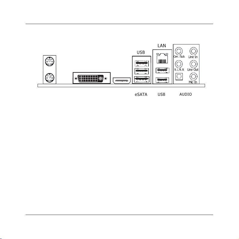
1.4 Connecting Rear Panel I/O Devices .......................................................................................7
Chapter 2 Hardware Setup....................................................................................... 8
2.1 Choosing a Computer Chassis...............................................................................................8
2.2 Installing Mainboard ............................................................................................................8
2.3 Installation of Memory Modules ............................................................................................9
2.4 Connecting Peripheral Devices ............................................................................................ 12
2.4.1 Serial ATA Connectors ..................................................................................................12
2.4.2 PCI slot....................................................................................................................... 12
Chapter 3 Jumpers & Headers Setup .......................................................................13
Chapter 4 BIOS Setup Utility ...................................................................................18
4.1 About BIOS Setup.............................................................................................................. 18
4.2 To Run BIOS Setup............................................................................................................18
4.3 About CMOS...................................................................................................................... 18
4.4 The POST (Power On Self Test) .......................................................................................... 18
4.5 BIOS Setup — CMOS Setup Utility....................................................................................... 19
4.5.1 CMOS Setup Utility....................................................................................................... 19
4.5.2 Control Keys................................................................................................................ 20
4.5.3 Main Menu .................................................................................................................. 21
4.5.4 Advanced Setting......................................................................................................... 24
4.5.5 Boot Setting ................................................................................................................ 29
4.5.6 Security Setting ........................................................................................................... 31
4.5.7 Power Setting.............................................................................................................. 32
4.5.8 PC&Health................................................................................................................... 34
4.5.9 Exit Setting ................................................................................................................. 35
Chapter 5 Driver Installation ...................................................................................38

MINIX H55-HD User's Manual
- 4 -
Chapter 1 Introduction
1.1 Package Checklist
Thank you for choosing our product.
Please check the following packing and accessories, if there is any broken or part missing,
please contact with your franchiser.
• Rear I/O Panel X 1
• User's Manual X 1
• Driver/Utility CD X 1
• Serial ATA Signal Cable X 1
• Serial ATA Power Cable X 1 (Optional)
The items listed above are for reference only, and are subject to change without notice.

MINIX H55-HD User's Manual
- 5 -
1.2 Specications
CPU
- Supports Intel®Core™ i7-800 / Core™ i5 /Core™ i3 Processors in the
LGA1156 Package
- Supports Intel®Turbo-boost Technology
Main Chipset -Intel®H55 Express Chipset
Main Memory - Support 2x1.5V DDR3 DIMM socket supporting up to 8GB of system memory
- Support for DDR3 1066/1333/1600(OC)MHz memory modules
BIOS
- AMI BIOS, supports Plug&Play
- Supports Advanced Power Management ACPI,STR
- CPU temperature, Fan speed, System Voltage monitoring
Rear Panel I/O
- 1 x PS/2 Keyboard port
- 1 x PS/2 Mouse port
- 1 x DVI port
- 1 x HDMI port
- 1 x SPDIF_OUT port
- 1 x RJ45 port
- 4 x USB 2.0 ports
- 1 x eSATA ports
-5 x Audio jacks (Line In / Line Out / MIC In/ Rear Speaker Out /Center
Subwoofer Speaker Out)
Internal I/O
Connectors
- 1 x 20-pin ATX main power connector
- 1 x 4-pin ATX 12V power connector
- 4 x SATA 3Gb/s connectors
- 1 x System fan header
- 1 x CPU FAN header
- 1 x Front panel header
- 1 x Front panel audio header
- 1 x SPDIF_OUT header
- 1 x SPEAK header
- 2 x USB 2.0 headers for additional 4 USB 2.0 ports (by cables)
Sound - Onboard 8-channel HD Audio Codec
- Front Panel Jumper, provides stereo MIC port on front panel
Onboard LAN - Onboard 10/100/1000Mbps compatible LAN (Optional)
Expansion Slots - 1 x PCIE slot
Form Factor Mini ITX (170mm*170mm)

MINIX H55-HD User's Manual
- 6 -
1.3 Mainboard Layout
(This picture is only for reference)
US B SATA_
USB L AN 1_
AUD IO
BAT
PCIE1
F AUD IO_
DVI
HDM I
FPANEL
JSPDIF
SPEAK
JBAT
SATA1
SATA2
JME
FUSB1
FUSB2
SFAN
LPC1
PWR12V
CFAN
JH55ITX01 V1 0
170 170
.
*
SATA3
SATA4
JKB
PS 2

MINIX H55-HD User's Manual
- 7 -
1.4 Connecting Rear Panel I/O Devices
The rear I/O part of these mainboard provides the following I/O ports:
(This picture is only for reference)
• PS/2 Mouse: Connects to a PS/2 mouse.
• PS/2 Keyboard: Connects to a PS/2 keyboard.
• DVI: Connects to a monitor's DVI input.
• eSATA:Connects to peripherial SATA devices.
• HDMI:Connects to multimedia devices of HDMI protocol.
• USB: The USB ports are used to connect USB 2.0/1.1 devices such as scanner, speakers,
keyboard, mouse, hub, digital camera, joystick, etc.
• LAN: The LAN port allows the motherboard to connect to a local area network by means of
a network hub.
• AUDIO(Rear Panel Audio):
Cen./Sub. (Center / Subwoofer): Connects to the center and subwoofer channel in the 7.1
channel audio system.
R.L./R.R. (Rear Left / Rear Right): Connects to the rear left and rear right channel in the 7.1
channel audio system.
Line-in (Light Blue): This jack is used to connect to the line out from any external audio
sources such as MP3 player, CD player, AM/FM radio tuner, etc.
Line-out (Front Left/Right Jack, Lime): This jack is used to connect to the front left and
right channel speakers of the audio system.
Mic-in (Pink): This jack is used to connect an external microphone.
HDMIDVI
SPDIF 0UT_
PS 2 Mouse
PS 2 Keyboard

MINIX H55-HD User's Manual
- 8 -
Chapter 2 Hardware Setup
2.1 Choosing a Computer Chassis
• Choose a chassis big enough to install this mainboard.
• As some features for this mainboard are implemented by cabling connectors on the
mainboard
to indicators and switches or buttons on the chassis, make sure your chassis supports all the
features required.
• If there is possibility of adopting some more hard drives, make sure your chassis has sufcient
power and space for them.
• Most chassis have alternatives for I/O shield located at the rear panel. Make sure the I/O
shield
of the chassis matches the I/O port conguration of this mainboard. You can nd
an I/O shield
specically designed for this mainboard in its package.
2.2 Installing Mainboard
Most computer chassis have a base with many mounting holes to allow the mainboard to be
securely attached, and at the same time, prevent
the system from short circuits. There are two ways
to attach the mainboard to the chassis base:
(1)with studs, or (2) with spacers.
Basically, the best way to attach the board is with
studs. Only if you are unable to do this should you
attach the board with spacers. Line up the holes on
the board with the mounting holes on the chassis.
If the holes line up and there are screw holes, you
can attach the board with studs. If the holes line
up and there are only slots, you can only attach with
spacers. Take the tip of the spacers and insert them into the slots. After doing this to all the slots,
you can slide the board into position aligned with slots. After the board has been positioned,
check to make sure everything is OK before putting the chassis back on.
To install this mainboard:
1. Locate all the screw holes on the mainboard and the chassis base.
2. Place all the studs or spacers needed on the chassis base and have them tightened.
3. Face the mainboard’s I/O ports toward the chassis’s rear panel.
4. Line up all the mainboard’s screw holes with those studs or spacers on the chassis.
5. Install the mainboard with screws and have them tightened.

MINIX H55-HD User's Manual
- 9 -
2.3 Installation of the CPU and CPU Cooler
Before installing the CPU, please comply with the following conditions:
1. Please make sure that the mainboard supports the CPU.
2. Please take note of the one indented corner of the CPU. If you install the CPU in the wrong
direction, the CPU will not insert properly. If this occurs, please change the insert direction
of the CPU.
3. Please add an even layer of heat sink paste between the CPU and CPU cooler.
4. Please make sure the CPU cooler is installed on the CPU prior to system use, otherwise
overheating and permanent damage of the CPU may occur.
5. Please set the CPU host frequency in accordance with the processor specications. It is not
recommended that the system bus frequency be set beyond hardware specications since
it does not meet the required standards for the peripherals. If you wish to set the frequen-
cy beyond the proper specications, please do so according to your hardware
specications including the CPU, graphics card, memory, hard drive, etc.
2.3.1 Installation of the CPU
1. O pe n th e so cke t le ve r by
pushing the lever down and away
from the socket .
2. Lift the load plate and remove the plastic protective
socket cover. Do not touch the socket contacts and do
not discard the protective socket cover. Always replace
with the protective socket cover if the processor is being
removed from the socket.

MINIX H55-HD User's Manual
- 10 -
2.3.2 Installation of the CPU Cooler
For proper installation, please kindly refer to the instruction manuals of your CPU Cooler.
3.Position the CPU over the
socket, ensuring that the gold
triangle is on the bottom-left
corner of the socket, and then
fit the socket alignment keys
into the CPU notches. (marked
with circle)
5. Insert the load lever under the retention tab.
4. Close the load plate, and then push down the load lever,
please ensure that the front edge of the load plate slides
UNDER the retention knob (marked with circle).

MINIX H55-HD User's Manual
- 11 -
2.3 Installation of Memory Modules
This mainboard provides two 1.5v DDR3 DIMM slots, which supports dual channel memory
technology. To activate the dual channel conguration, you need to install two identical
(same brand, speed, size and chip-type) memory modules into these DIMM slots. Otherwise
the memory will only operate at single channel mode.
For dual channel DDR3 installation:
Populate two DDR3 DIMM modules of the same type and size into slots [DIMM1] + [DIMM2].
To install system memory:
1. Power off the computer and unplug the
AC power cord before installing or
removing memory modules.
2. Locate the DIMM slot on the board.
3. Hold two edges of the DIMM module
carefully, keep away from touching its
connectors.
4. Align the notch key on the module with
the rib on the slot.
5. Firmly press the module into the slots until the ejector tabs at both sides of the slot
automatically snap into the mounting notch. Do not force the DIMM module in with extra
force as the DIMM module only ts in one direction.
6. To remove the DIMM modules, push the two ejector tabs on the slot outward
simultaneously, and then pull out the DIMM module.
Static electricity can damage the electronic components of the computer or optional boards.
Before starting these procedures, ensure that you are discharged of static electricity by
touching a grounded metal object briey.

MINIX H55-HD User's Manual
- 12 -
2.4 Connecting Peripheral Devices
2.4.1 Serial ATA Connectors
Each SATA connector serves as one single channel to connect one SATA device by SATA cable.
2.4.2 PCIE slot
Install PCIE card into slot “PCIE1” .
USB SATA_
USB LA N1_
AUDI O
BAT
PCIE1
F AUDI O_
DVI
HDMI
FPANEL
JSPDIF
SPEAK
JBAT
SATA1
SATA2
JME
FUSB1
FUSB2
SFAN
LPC1
PWR12V
CFAN
JH55ITX01 V1 0
170 170
.
*
SATA3
SATA4
JKB
PS 2

MINIX H55-HD User's Manual
- 13 -
Chapter 3 Jumpers & Headers Setup
Quick Components Guide
NO. Layout Page NO. No. Layout Page NO.
1 F_AUDIO 14 8 FPANEL 15
2 SFAN 14 9 ATXPWR 16
3 FUSB1/FUSB2 15 10 CFAN 17
4 JME 15 11 PWR12V 16
5 JBAT 15 12 JKB 17
6 SPEAK 15 13 LPC1 17
7 JSPDIF 16
USB SATA_
USB LA N1_
AUDI O
BAT
PCIE1
F AUDI O_
DVI
HDMI
FPANEL
JSPDIF
SPEAK
JBAT
SATA1
SATA2
JME
FUSB1
FUSB2
SFAN
LPC1
PWR12V
CFAN
JH55ITX01 V1 0
170 170
.
*
SATA3
SATA4
JKB
PS 2
1 2 34567
8
9
10
11
12
13

MINIX H55-HD User's Manual
- 14 -
Checking Jumper Settings
• For a 2-pin jumper, plug the jumper cap on both pins will make it CLOSE (SHORT). Remove the
jumper cap, or plug it on either pin (reserved for future use) will leave it at OPEN position.
• For 3-pin jumper, pin 1~2 or pin 2~3 can be shorted by plugging the jumper cap in.
How to identify the PIN1 jumpers?
Please check the mainboard carefully, the PIN1 is marked by "1" or white thick line.
1-F_AUDIO(Front Panel Audio Connection Header)
Pin No. Header HD Audio Denition AC97 Audio Denition
1 PORT1L Microphone_Left Microphone
2 AGND Ground Ground
3 PORT1R Microphone_Right MIC Power
4 PRESENCE# -ACZ_DET N/A
5 PORT2R Line2_Right Line out (R)
6 SENSE1_RETURN AuD_R_Return N/A
7 SENSE_SEND FAUDIO_JD N/A
8 No Pin N/A N/A
9 PORT2L Line2_Left Line Out(L)
10 SENSE2_RETURN AuD_L_Return N/A
2-SFAN1(Fan Power Connectors Header)
SFAN1:System fan connectors
Pin No. Denition
1 GND
2 +12V
3 RPM
These fan connectors are not jumpers.
DO NOT place jumper caps on these
connectors.
1 2
910
F AUDIO_

MINIX H55-HD User's Manual
- 15 -
6/8-SPEAK/FPANEL(Speaker Headers & Front Panel Switches)
HD_LED (Red): Hard Driver LED connector
This connector connects to the case-mounted
HD LED cable, and the LED will light when the
hard drive(s) is/are being accessed.
RST (Blue): Reset Switch
This connector connects to the case-mounted
reset switch which allows you to reboot without
having to power-off the system and thus prolonging the life of the power supply or system.
PWR_ON (Black): Power Switch
Depending on the setting in the BIOS setup, this switch serves two functions which will allow
you to power-on/off the system or to enter the suspend mode.
PWR_LED (Green): Power/Standby LED
When the system's power is on, this LED will light. When the system is in the S1 (POS - Power
SPEAK:
Pin No. Denition
1 SPK +
2 NC
3 NC
4 SPK -
3-FUSB1/FUSB2(Additional USB Port Headers)
Pin No. Denition Pin No. Denition
1 VCC 2 VCC
3 Data 0- 4 Data 1-
5 Data 0+ 6 Data 1+
7 Ground 8 Ground
10 NC
5-JBAT(CMOS Memory Clearing Header)
The time to clear the CMOS memory occurs when (a) the CMOS data becomes corrupted, (b)
you forgot the supervisor or user password preset in the BIOS menu, (c) you are unable to
boot-up the system because the CPU ratio/clock was incorrectly set in the BIOS menu, or (d)
whenever there is modication on the CPU or memory modules.
This header uses a jumper cap to clear the CMOS
memory and have it recongured to the default values
stored in BIOS.
• Pins 1 and 2 shorted (Default): Normal operation.
• Pins 2 and 3 shorted: Clear CMOS memory.
+-
+-
PW R LED_PW R ON_
HD L E D_RST
4-JME
This header uses a jumper cap to refresh the motherboard's BIOS.
Pins 1 and 2 shorted:Refresh the BIOS. Pins 1 and 2 disconnected:can't refresh the BIOS.
JM E
12

MINIX H55-HD User's Manual
- 16 -
34
GND GND
+12V
+12V
1 2
PWR12V
11/9- ATX Power Input Connectors
ATXPWR (ATX Power) connector
We recommend to use our motherboard with a power supply that complies with the ATX12V
Power Supply Design Guide Version 1.1. Every ATX12V power supply unit has a standard
24-pin ATX main power connector that must be plugged into this connector. If you would like
to use an old power supply with only a 20-pin ATX main power connector, then please plug
the 20-pin ATX main power connector along with pin 1 and pin 13.
PWR12V (+12V Power) connector
Your power supply unit may come with a 4-pin or 8-pin +12V power connector. The +12V
power enables the delivery of more +12VDC current to the CPU's Voltage Regulator Module
(VRM). If available, please use the 8-pin power; otherwise please connect the 4-pin power
to this connector.
on Suspend) or S3 (STR - Suspend to RAM, optional) state, it will blink every second.
SPEAKER (Yellow or Black): Speaker Connector
This 4-pin connector connects to the case-mounted speaker.
7-S/PDIF Output Connection Header
S/PDIF (Sony/Philips Digital Interface) is a standard audio transfer le format.
It is usually found on digital audio equipment such as a DAT (Digital Audio
Tape) machine or audio processing device. It allows the transfer of audio from
one le to another without the conversion to and from an analog format, which
could degrade the signal quality.
113
10 20
+ .3 3V
+5V
GND
PWRGD
PS ON-
N C/
+ .3 3V
GND
+12V
+5V
GND
+5VSB
+ .3 3V
-12V
GND
GND
GND
GND
+5V
+5V
ATXPWR
1VCC
NC
OUT
GND

MINIX H55-HD User's Manual
- 17 -
13-LPC
This set of headers are reserved for internal debug purpose.
10-CFAN(CPU Fan Power Connectors Header)
These fan connectors are not jumpers.
DO NOT place jumper caps on these
connectors.
CFAN:CPU fan connectors
Pin No. Denition
1 GND
2 +12V
3 RPM
4 Control
12-JKB(Keyboard Power Function)
Pin 1-2 short: Disabled power on by keyboard.
Pin 2-3 short: Support power on by keyboard.
JKB:
Disable (Default)
Enable

MINIX H55-HD User's Manual
- 18 -
Chapter 4 BIOS Setup Utility
BIOS stands for Basic Input and Output System. It was once called ROM BIOS when it was stored
in a Read-Only Memory (ROM) chip. Now manufacturers would like to store BIOS in EEPROM which
means Electrically Erasable Programmable Memory. BIOS used in this series of mainboard is stored
in EEPROM, and is the rst program to run when you turn on your computer.
BIOS performs the following functions:
1. Initializing and testing hardware in your computer (a process called "POST", for Power On Self
Test).
2. Loading and running your operating system.
3. Helping your operating system and application programs manage your PC hardware by means of
a set of routines called BIOS Run-Time Service.
4.1 About BIOS Setup
BIOS Setup is an interactive BIOS program that you need to run when:
1. Changing the hardware of your system. (For example: installing a new Hard Disk etc.)
2. Modifying the behavior of your computer. (For example: changing the system time or date, or
turning special features on or off etc.)
3. Enhancing your computer's behavior. (For example: speeding up performance by turning on
shadowing or cache)
4.2 To Run BIOS Setup
First access BIOS setup menu by pressing <F1> key after “POST” is complete (before OS is
loaded). After the rst BIOS be setupped(or loaded default values) and save, the <DEL> key will
be pressed if you will enter BIOS setup menu.
4.3 About CMOS
CMOS is the memory maintained by a battery. CMOS is used to store the BIOS settings you have
selected in BIOS Setup. CMOS also maintains the internal clock. Every time you turn on your
computer, the BIOS Looks into CMOS for the settings you have selected and congures your
computer accordingly. If the battery runs out of power, the CMOS data will be lost and POST will
issue a “CMOS invalid” or “CMOS checksum invalid” message. If this happens, you have to replace
the battery and check and congure the BIOS Setup for the new start.
4.4 The POST (Power On Self Test)
POST is an acronym for Power On Self Test. This program will test all things the BIOS does

MINIX H55-HD User's Manual
- 19 -
before the operating system is started. Each of POST routines is assigned a POST code, a unique
number which is sent to I/O port 080h before the routine is executed.
4.5 BIOS Setup — CMOS Setup Utility
4.5.1 CMOS Setup Utility
After powering up the system, the BIOS message appears on the screen,when the rst time or
when CMOS setting wrong, there is following message appears on the screen , but if the rst
rst BIOS be setuped(or loaded default values) and save, the <DEL> key will be pressed if you
will enter BIOS setup menu.
If this message disappears before you respond, restart the system by pressing <Ctrl> + <Alt>+
<Del> keys, or by pressing the reset button on computer chassis. Only when these two methods
should be fail that you restart the system by powering it off and then back on.
After pressing <F1> or <Del> key, the main menu appears.
Press F1 to Run SETUP
• In order to increase system stability and performance, our engineering staff is constantly
improving the BIOS menu. The BIOS setup screens and descriptions illustrated in this manual
are for your reference only, and may not completely match with what you see on your screen.
• Do not change the BIOS parameters unless you fully understand its function.
BIOS SETUP UTILITY
Main Advanced Boot Security Power PC&Health Exit
►
System Information
←
Select Screen
↑↓
Select Item
Enter Go to Sub Screen
F1 General Help
F10 Save and Exit
ESC Exit
System Time
System Date
Power On Beep
[20:50:32]
[Tue 09/03/2009]
[Enabled]
►
SATA Port 1
►
SATA Port 2
►
SATA Port 3
►
SATA Port 4
►
AHCI Devices
: [ST380215AS]
: [Not Detected]
: [Not Detected]
: [Not Detected]
v02.61 (C)Copyright 1985-2006, American Megatrends, Inc.

MINIX H55-HD User's Manual
- 20 -
The menu bar on top of the screen has the following main items:
Main
For changing the basic system conguration.
Advanced For changing the advanced system settings.
Boot
For changing the system boot conguration.
Security
For changing the system security setttings.
Power
For changing the advanced power management(APM) conguration.
Exit For selecting the exit options and loading default settings.
Control Key(s) Function Description
←
/
→
Move cursor left or right to select Screens
↑
/
↓
Move cursor up or down to select items
+/
-To Change option for the selected items
<Enter> To bring up the selected screen
<ESC>
Main Menu - Quit and not save changes into CMOS Status Page
Setup Menu and Option Page Setup Menu - Exit current page and
return to Main Menu
<F1> General help
<F2/F3> Change Colors
<F7> Discard Changes
<F8> Load Failsafe Defaults
<F9> Load Optimal Defaults
<F10> Save conguration changes and exit setup
4.5.2 Control Keys
Press F1 to pop up a small help window that describes the appropriate keys to use and the
possible selections for the highlighted item.
Please check the following table for the function description of each control key.
Table of contents
Other Minix Motherboard manuals