MINN KOTA MK106D User manual
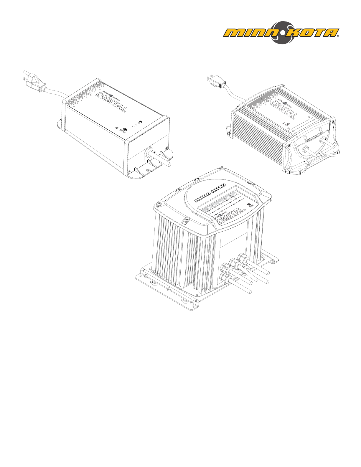
DIGITAL
ONBOARD CHARGERS
USER MANUAL
CHA RGING ( 1-10A)
FUL L CHARG E (0-1A)
CHE CK CONN ECTIO N
2B ank • 10 Amps per B ank • 20 Amps Total
Ignition Pro tected • Water proof Const ruction*
For Use with 12 Volt /6 Cell Batt eries
that are Floo ded/Wet Cel l, Maintena nce Free
or Starved El ectroly te (AGM) Only
*MANUFACTURER’ S ENCLOSURE RATING
ON-BOARD BATTERY CHA RGER
MK220D
CHAR GING (1-6 A)
FULL C HARGE (0 -1A)
CHECK C ONNEC TION
1 Bank • 6Am ps per Bank • 6Amps Total
Ignition Protected • Waterproof Construction*
For Use with 12 Volt/6 Cell B atteries
that are Floode d/Wet Cell, Mainten ance Free
or Starved Elec trolyte (AGM) Only
*MANUFACTURER’S ENC LOSURE RATING
ON-BOARD BATTERY CH ARGER
MK106D
CHA RGIN G (1-10A )
FUL L CHAR GE (0-1 A)
CHE CK CON NECT ION
MK440D
MK106D
MK210D
MK220D
MK315D
MK330D
MK440D

2 | minnkotamotors.com ©2017 Johnson Outdoors Marine Electronics, Inc.
INTRODUCTION
Made by Minn Kota
Johnson Outdoors
Marine Electronics, Inc.
121 Power Drive
Mankato, MN 56001 USA
Battery Chargers
Produced in 2014
Digital Charger
MODEL 1866150
SER NO M365 MK12345
NOTE: The serial number on your On Board Charger
is located on the input cord and the bottom of the
charger (MK440D model serial numbers are located
on the front.)
EXAMPLE
THANK YOU
Thank you for choosing Minn Kota. We believe that you should spend more time fishing, that’s why we build the smartest,
toughest, most intuitive marine products on the water. Every aspect of a Minn Kota product is thought out and rethought until it’s
good enough to bear our name. Countless hours of research and testing provide you the advantages of a Minn Kota product that
can truly take you “Anywhere. Anytime.” We don’t believe in shortcuts. We are Minn Kota. And we are never done helping you
catch more fish.
Model:__________________________________________________________________________________________________________________________
Serial Number: ________________________________________________________________________________________________________________
Purchase Date: ________________________________________________________________________________________________________________
Store Where Purchased: _____________________________________________________________________________________________________
REGISTRATION
Remember to keep your receipt and immediately register
your product. A registration card is included with your
product or you can complete registration on our website at
minnkotamotors.com.
SERIAL NUMBER
Your Minn Kota 11-character serial number is very
important. It helps to determine the specific model and
year of manufacture. When contacting Consumer Service
or registering your product, you will need to know your
product’s serial number. We recommend that you write the
serial number down so that you have it available for future
reference.
NOTE: Do not return your Minn Kota charger to your retailer. Your retailer is not authorized to repair or replace this unit.
You may obtain service by calling Minn Kota at (800) 227-6433. Please include proof of purchase, serial number and
purchase date for warranty service.
PRODUCT INFORMATION (FOR CONSUMER REFERENCE ONLY)
MK105PC
MODEL 1831050

minnkotamotors.com | 3
©2017 Johnson Outdoors Marine Electronics, Inc.
Table of ConTenTs
TABLE OF CONTENTS
SAFETY INSTRUCTIONS ............................................................................................................4
Important Safety Instructions ..................................................................................................4
Personal Precautions.................................................................................................................. 5
Preparing to Charge ....................................................................................................................6
Charger Locations........................................................................................................................6
Mounting the Charger ................................................................................................................. 7
DC Connection Precautions ...................................................................................................... 7
WARRANTY ......................................................................................................................................11
FEATURES........................................................................................................................................ 12
OPTIONAL INSTALLATION..................................................................................................... 13
Installing the MK-EC Extension Cable Accessory............................................................. 13
OPERATING INSTRUCTIONS................................................................................................. 15
Overview....................................................................................................................................... 15
General Operation...................................................................................................................... 16
Indicator LEDS ...........................................................................................................................16
Multi-Stage Charging.................................................................................................................17
Troubleshooting..........................................................................................................................18
MAINTENANCE INSTRUCTIONS..........................................................................................19
General Maintenance ................................................................................................................19
Inline Fuse ...................................................................................................................................20
Frequently Asked Questions .................................................................................................20
For Further Troubleshooting and Repair............................................................................ 22
COMPLIANCE STATEMENTS .................................................................................................23
Environmental Compliance Statement ................................................................................23
WEEE Directive..........................................................................................................................23
Disposal.........................................................................................................................................23
FCC Compliance..........................................................................................................................23
Industry Canada Compliance ................................................................................................. 24
Environmental Ratings ............................................................................................................ 24
PARTS DIAGRAM & PARTS LIST........................................................................................25
MK106D .......................................................................................................................................25
MK210D, MK220D, MK315D, MK330D............................................................................27
MK440D..................................................................................................................................... 29
NOTES ................................................................................................................................................. 31

4 | minnkotamotors.com ©2017 Johnson Outdoors Marine Electronics, Inc.
SAFETY INSTRUCTIONS
5. Do not operate charger with damaged cord or plug.
6. Do not operate charger if it has received a sharp blow, been dropped, or otherwise damaged in any way.
7. Do not disassemble charger.
8. To reduce risk of electric shock, unplug charger from outlet and disconnect from battery before attempting any maintenance or
cleaning. Turning off controls will not reduce this risk.
IMPORTANT SAFETY INSTRUCTIONS - SAVE THESE INSTRUCTIONS
1. SAVE THESE INSTRUCTIONS - This manual contains important safety and operating instructions for your Minn Kota battery
charger. The Minn Kota battery charger is a powerful electrical device. If incorrectly installed, configured or operated, the battery
charger can damage batteries and / or electrical equipment. Please thoroughly read the instructions and safety information
contained in this manual before operating the battery charger.
2. Use of an attachment not recommended or sold by Johnson Outdoors Marine Electronics, Inc. may result in a risk or fire,
electric shock, or injury to persons.
3. To reduce the risk of damage to electric plug and cord, pull by plug rather than cord when disconnecting charger.
4. An extension cord should not be used unless absolutely necessary. Use of improper extension cord could result in a risk of fire
and electric shock. If an extension cord must be used, make sure:
a) That pins on plug of extension cord are the same number, size and shape as those of plug on charger;
b) That extension cord is properly wired and in good electrical condition; and
c) That wire size is large enough for ac ampere rating of charger as specified in table.
MODEL
AWG SIZE
25' AC Extension Cord 50' AC Extension Cord 100' AC Extension Cord 150' AC Extension Cord
MK106D 18 AWG 18 AWG 18 AWG 16 AWG
MK210D 18 AWG 18 AWG 16 AWG 14 AWG
MK220D 18 AWG 18 AWG 14 AWG 12 AWG
MK315D 18 AWG 18 AWG 14 AWG 12 AWG
MK330D 18 AWG 16 AWG 14 AWG 12 AWG
MK440D 18 AWG 16 AWG 12 AWG 10 AWG
minnkotamotors.com | 5
©2017 Johnson Outdoors Marine Electronics, Inc.
SAFETY INSTRUCTIONS
10. External connections to the charger shall comply with the United States Coast Guard Electrical Regulation (33CFR183, SUB
PART 1).
WARNING
9. WARNING - RISK OF EXPLOSIVE GASES
a) WORKING IN VICINITY OF A LEAD-ACID BATTERY IS DANGEROUS. BATTERIES GENERATE EXPLOSIVE GASES
DURING NORMAL BATTERY OPERATION. FOR THIS REASON, IT IS OF UTMOST IMPORTANCE THAT YOU FOLLOW
THE INSTRUCTIONS EACH TIME YOU USE THE CHARGER.
b) To reduce the risk of battery explosion, follow these instructions and those published by the battery manufacturer and
manufacturer of any equipment you intend to use in the vicinity of the battery. Review cautionary markings on these
products and on engine.
11. PERSONAL PRECAUTIONS
a) Consider having someone close enough by to come to your aid when you work near a lead-acid battery.
b) Have plenty of fresh water and soap nearby in case acid contacts skin, clothing, or eyes.
c) Wear complete eye protection and clothing protection. Avoid touching eyes while working near battery.
d) If battery acid contacts skin or clothing, wash immediately with soap and water. If acid enters eyes, immediately flood eye
with running cold water for at least 10 minutes and get medical attention immediately.
e) NEVER smoke or allow a spark or flame in vicinity of battery or engine.
f) Be extra cautious to reduce risk of dropping a metal tool onto battery. It might spark or short-circuit battery or other
electrical part that may cause explosion.
g) Remove personal metal items such as rings, bracelets, necklaces, and watches when working with a lead-acid battery. A
lead-acid battery can produce a short-circuit current high enough to weld a ring or the like to metal, causing a severe burn.
h) Use charger for charging batteries only. It is not intended to supply power to a low voltage electrical system other than in
a starter-motor application. Do not use battery charger for charging dry-cell batteries that are commonly used with home
appliances. These batteries may burst and cause injury to persons and damage to property.
i) NEVER charge a frozen battery.
6 | minnkotamotors.com ©2017 Johnson Outdoors Marine Electronics, Inc.
SAFETY INSTRUCTIONS
g) Each DC output cord is six feet long. Make sure that all DC output cords can reach the batteries and that the AC power
cord can reach a power source. When using an extension cord, make the AC connection to the charger outside of the battery
compartment as far away as practical to reduce the risk of a spark igniting gasses in the compartment.
h) Do not shorten the DC output cords, as this can affect charger output.
i) If the DC output cords are not long enough, they may be lengthened by splicing and soldering 12 AWG (minimum) wire.
Each splice should be covered with dual wall adhesive lined heat shrink tubing to protect the joint from corroding. The splice
should be made between the fork in the output cable and the fuse holder. The fuse holder should always remain within 7” of
the battery terminals. The maximum extension length is 15 feet. You may contact the Minn Kota Service Department with any
questions.
k) Even though the Minn Kota charger is capable of operating in a high ambient temperature environment, a minimum of six
inches of unobstructed area should be allowed on all sides of the unit for proper air circulation and cooling. Proper cooling
and circulation will allow the charger to operate at peak efficiency.
l) Keyhole slots are not to be used for installing the charger.
WARNING
j) Do not splice the AC power cord, as this voids the three year Limited Warranty.
12. PREPARING TO CHARGE
a) If necessary to remove battery from boat or vehicle to charge, always remove grounded terminal from battery first. Make
sure all accessories in the boat or vehicle are off , so as not to cause an arc.
b) Be sure area around battery is well ventilated while battery is being charged.
c) Clean battery terminals. Be careful to keep corrosion from coming in contact with eyes.
d) Add distilled water to each cell until battery acid reaches level specified by battery manufacturer. Do not overfill. For a
battery without removable cell caps, such as valve regulated lead acid batteries, carefully follow manufacturer's recharging
instructions.
e) Study all battery manufacturer's specific precautions while charging and recommended rates of charge.
f) The Minn Kota charger will only charge 12 volt 6 cell LEAD-ACID: FLOODED/WET CELL, MAINTENANCE FREE, and
AGM/STARVED ELECTROLYTE batteries. Do not connect the output of the charger to any other voltage or battery type.
13. CHARGER LOCATION
a) Locate charger as far away from battery as dc cables permit.
b) Never place charger directly above battery being charged; gases from battery will corrode and damage charger.
c) Never allow battery acid to drip on charger when reading electrolyte specific gravity or filling battery.
d) Do not operate charger in a closed-in area or restrict ventilation in any way.
e) Do not set a battery on top of charger.
f) Do not mount the charger below the waterline of the boat or directly adjacent to fuel tanks.

minnkotamotors.com | 7
©2017 Johnson Outdoors Marine Electronics, Inc.
SAFETY INSTRUCTIONS
14. MOUNTING THE CHARGER - Due to the weight of the charger and the impact that boats routinely endure, take the time to
securely mount the charger to prevent damage. Mounting with nuts, bolts and washers is preferable to mounting with screws.
a) Charger was designed to be mounted in any orientation on the boat.
b) Use the largest diameter bolts possible and use all four mounting holes.
c) After marking the locations, set the charger aside and drill the holes.
d) Apply a marine grade silicone sealant in each of the drilled holes to create a waterproof seal.
e) Then secure the charger in place using the mounting hardware.
WARNING
f) Make sure the charger is disconnected from ac power before connecting the batteries to the output cords.
NOTE: Your battery charger is supplied with an AC plug holder designed to hold the power cord plug when not in use.
Mount the AC plug holder with four screws in a convenient dry site to prevent corrosion to the AC plug and to prevent the
AC plug from making contact with the battery posts.
UTION
g) Before making any connections to batteries in a confined space (such as a battery compartment of a boat), open the door
or hatch of the compartment and allow it to air out for 15 minutes. This allows any gasses that have accumulated in the
compartment to escape.
15. DC CONNECTION PRECAUTIONS
a) Connect and disconnect dc output terminals only after removing ac cord from electric outlet. Never allow output terminals
to touch each other.
b) Attach output terminals to battery and chassis as indicated in 16(e), 16(f), and 17(b).
8 | minnkotamotors.com ©2017 Johnson Outdoors Marine Electronics, Inc.
SAFETY INSTRUCTIONS
a) Position ac and dc cords to reduce risk of damage by hood, door, or moving engine part.
b) Stay clear of fan blades, belts, pulleys. and other parts that can cause injury to persons.
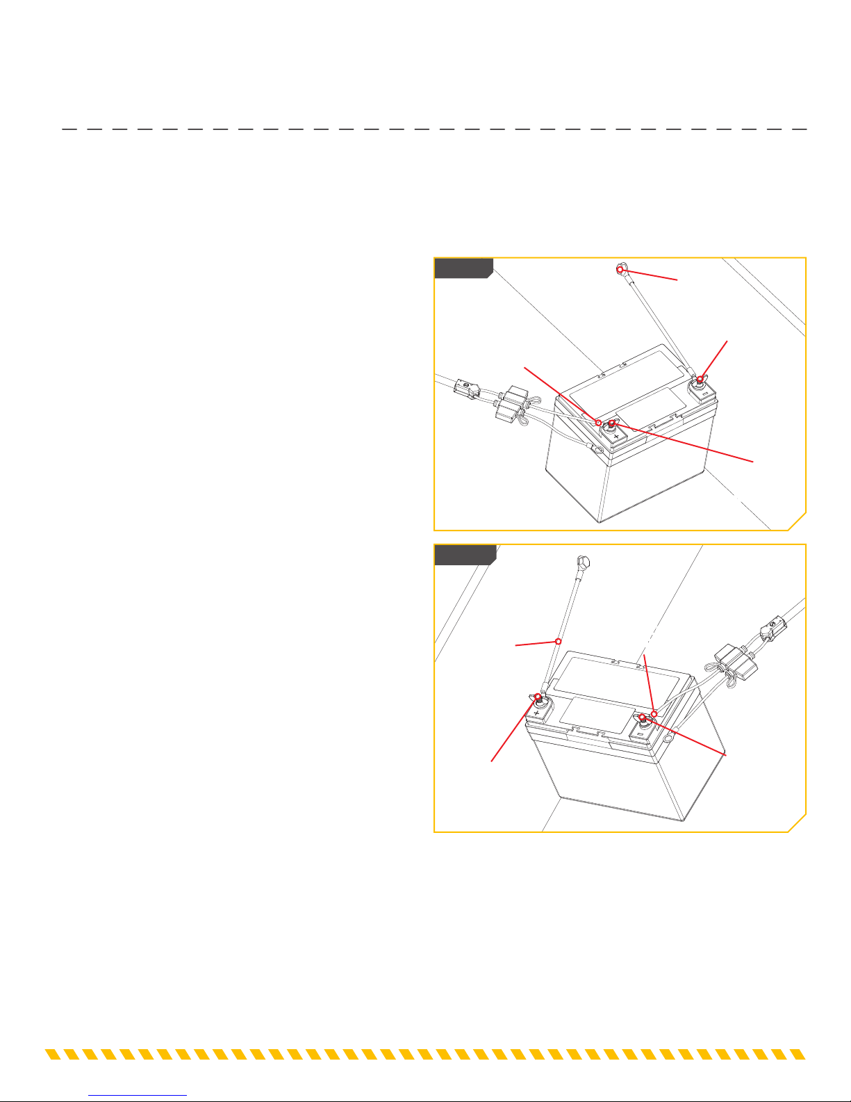
c) Check polarity of battery posts. POSITIVE (POS, P, +)
battery post usually has a larger diameter than NEGATIVE
(NEG, N, -) post.
d) Determine which post of battery is grounded
(connected) to the chasis. If negative post is grounded to
chasis (as in most vehicles), see (e). If positive post is
grounded to the chasis, see (f).
e) For negative-grounded vehicle, connect POSITIVE
(RED) output terminal from battery charger to POSITIVE
(POS, P, +) ungrounded post of battery. Connect NEGATIVE
(BLACK) output terminal to vehicle chassis or engine block
away from battery. Do not connect output terminal to
carburetor, fuel lines, or sheet-metal body parts. Connect to
a heavy gage metal part of the frame or engine block.
(Refer to Figure 1).
Figure 1
Figure 2
Ground
Ground
NEGATIVE (Black)
Output Terminal
POSITIVE (Red)
Output Terminal
POSITIVE
(POS, P, +)
Battery Post
POSITIVE
(POS, P, +)
Battery Post
NEGATIVE
(NEG, N, -)
Battery Post
NEGATIVE
(NEG, N, -)
Battery Post
f) For positive-grounded vehicle, connect NEGATIVE
(BLACK) output terminal from battery charger to
NEGATIVE (NEG, N, -) ungrounded post of battery.
Connect POSITIVE (RED) output terminal to vehicle
chassis or engine block away from battery. Do not connect
output terminal to carburetor, fuel lines, or sheet-metal
body parts. Connect to a heavy gage metal part of the
frame or engine block. (Refer to Figure 2).
g) When disconnecting charger, disconnect AC cord,
remove output terminal from vehicle chassis, and then
remove output terminal from battery terminal.
h) See operating instructions for length of charge
information.
16. FOLLOW THESE STEPS WHEN BATTERY IS INSTALLED IN VEHICLE. A SPARK NEAR BATTERY MAY CAUSE
BATTERY EXPLOSION. TO REDUCE RISK OF A SPARK NEAR BATTERY:

minnkotamotors.com | 9
©2017 Johnson Outdoors Marine Electronics, Inc.
SAFETY INSTRUCTIONS
UTION
21. CAUTION - When using an extension cord, make the AC connection to the charger outside of the battery compartment as far
away as practical to reduce the risk of a spark igniting gasses in the compartment.
UTION
22. CAUTION - Even though the Minn Kota charger is capable of operating in a high ambient temperature environment, a
minimum of six inches of unobstructed area should be allowed on all sides of the unit for proper air circulation and cooling.
Proper cooling and circulation will allow the charger to operate at peak efficiency.
DANGER
18. DANGER - Never alter AC cord or plug provided – if it will not fit outlet, have proper outlet installed by a qualified electrician.
Improper connection can result in a risk of an electric shock.
DANGER
19. DANGER - Do not attempt to repair or service the charger yourself. Opening the charger may expose you to high voltages,
the risk of electric shock, and other hazards.
DANGER
20. DANGER - Do not splice the AC power cord.
17. FOLLOW THESE STEPS WHEN BATTERY IS OUTSIDE VEHICLE. A SPARK NEAR THE BATTERY MAY CAUSE
BATTERY EXPLOSION. TO REDUCE RISK OF A SPARK NEAR BATTERY:
a) Check polarity of battery posts. POSITIVE (POS, P, +) battery post usually has a larger diameter than NEGATIVE (NEG, N,
-) post.
b) Connect POSITIVE (RED) charger clip to POSITIVE (POS, P, +) post of battery. Connect NEGATIVE (BLACK) charger clip
to NEGATIVE (NEG, N, -) post of battery.
c) Do not face battery when making final connection.
d) When disconnecting charger, always do so in reverse sequence of connecting procedure.
e) A marine (boat) battery does not need to be removed and charged on shore. However, instructions must be followed for
location of charger when permanently mounted or used on board.
10 | minnkotamotors.com ©2017 Johnson Outdoors Marine Electronics, Inc.
SAFETY INSTRUCTIONS
UTION
24. CAUTION - We recommend that you not recharge your battery, with the watercraft or motor lower unit in the water during
electrical storms. Severe damage to the motor or charging system may occur if lightning strikes nearby or if storm related high
voltage conditions exist.
UTION
25. CAUTION - If using a generator to power the charger, it must have a clean output and be safe for use on electrical equipment.
Generators with a sine wave output can be used to power this charger. See the table in the Maintenance Instructions for power
requirements.
DANGER
26. DANGER - Damaged cords and plugs can cause electric shock or electrocution.
UTION
23. CAUTION - Before making any connections to batteries in a confined space (such as a battery compartment of a boat), open
the door or hatch of the compartment and allow it to air out for 15 minutes. This allows any gasses that have accumulated in the
compartment to escape.

WARRANTY ON MINN KOTA BATTERY CHARGERS
Johnson Outdoors Marine Electronics, Inc. (“JOME”) extends the following limited warranty to the original retail purchaser only. Warranty coverage is not
transferable.
Minn Kota Limited Three-Year Replacement Warranty on the Entire Product
JOME warrants to the original retail purchaser only that the purchaser’s new Minn Kota battery charger and battery maintainer will be materially free from
defects in materials and workmanship appearing within three (3) years after the date of purchase. JOME will (at its option) replace, free of charge, any
charger found by JOME to be defective during the term of this warranty. Such replacement shall be the sole and exclusive liability of JOME and the sole and
exclusive remedy of the purchaser for breach of this warranty.
Exclusions & Limitations
This limited warranty does not apply to products that have been used commercially or for rental purposes. This limited warranty does not cover normal
wear and tear, blemishes that do not affect the operation of the product, or damage caused by accidents, abuse, alteration, modification, shipping
damages, acts of God, negligence of the user or misuse, improper or insufficient care or maintenance. DAMAGE CAUSED BY THE USE OF OTHER
REPLACEMENT PARTS NOT MEETING THE DESIGN SPECIFICATIONS OF THE ORIGINAL PARTS WILL NOT BE COVERED BY THIS
LIMITED WARRANTY. The cost of normal maintenance or replacement parts which are not in breach of the limited warranty are the responsibility of the
purchaser. Prior to using products, the purchaser shall determine the suitability of the products for the intended use and assumes all related risk and liability.
Any assistance JOME provides to or procures for the purchaser outside the terms, limitations or exclusions of this limited warranty will not constitute a
waiver of the terms, limitations or exclusions, nor will such assistance extend or revive the warranty. JOME will not reimburse the purchaser for any expenses
incurred by the purchaser in repairing, correcting or replacing any defective products or parts, except those incurred with JOME’s prior written permission.
JOME’S AGGREGATE LIABILITY WITH RESPECT TO COVERED PRODUCTS IS LIMITED TO AN AMOUNT EQUAL TO THE PURCHASER’S
ORIGINAL PURCHASE PRICE PAID FOR SUCH PRODUCT.
Minn Kota Service Information
To obtain warranty service in the U.S., the product believed to be defective, and proof of original purchase (including the date of purchase), must be presented
to Minn Kota’s factory service center in Mankato, MN. Any charges incurred for service calls, transportation or shipping/freight to/from the Minn Kota
Authorized Service Center or factory, labor to haul out, remove, re-install or re-rig products removed for warranty service, or any other similar items are the
sole and exclusive responsibility of the purchaser. Products purchased outside of the U.S. must be returned prepaid with proof of purchase (including the
date of purchase and serial number) to any Authorized Minn Kota Service Center in the country of purchase. Warranty service can be arranged by contacting
a Minn Kota Authorized Service Center or by contacting the factory at 1-800-227-6433 or email service@minnkotamotors.com. Products repaired or
replaced will be warranted for the remainder of the original warranty period [or for 90 days from the date of repair or replacement,
whichever is longer]. For any product that is returned for warranty service that JOME finds to be not covered by or not in breach of this
limited warranty, there will be a billing for services rendered at the prevailing posted labor rate and for a minimum of at least one hour.
NOTE: Do not return your Minn Kota product to your retailer. Your retailer is not authorized to repair or replace products.
NOTE: THERE ARE NO EXPRESS WARRANTIES OTHER THAN THESE LIMITED WARRANTIES. IN NO EVENT SHALL ANY
IMPLIED WARRANTIES INCLUDING ANY IMPLIED WARRANTIES OF MERCHANTABILITY OR FITNESS FOR PARTICULAR
PURPOSE, EXTEND BEYOND THE DURATION OF THE RELEVANT EXPRESS LIMITED WARRANTY. IN NO EVENT SHALL JOME BE
LIABLE FOR PUNITIVE, INDIRECT, INCIDENTAL, CONSEQUENTIAL OR SPECIAL DAMAGES. Without limiting the foregoing, JOME
assumes no responsibility for loss of use of product, loss of time, inconvenience or other damage.
Some states do not allow limitations on how long an implied warranty lasts or the exclusion or limitation of incidental or consequential damages, so the above
limitations and/or exclusions may not apply to you. This warranty gives you specific legal rights and you may also have other legal rights which vary from state
to state.
minnkotamotors.com | 11
©2017 Johnson Outdoors Marine Electronics, Inc.
WARRANTY
NOTE: There are no serviceable components inside the charger.

12 | minnkotamotors.com ©2017 Johnson Outdoors Marine Electronics, Inc.
FEATURES
CHARGING (1-10A)
FULL CH ARGE (0-1A)
CHECK CONNECTIO N
2 Bank • 10 Am ps per Bank • 20 A mps Total
Ignition Protected • WaterproofConstruction*
For Use w ith 12 Volt/6 Cell B atterie s
that ar e Flooded/ Wet Cell, Mai ntenance Fre e
or Star ved Electr olyte (AGM) On ly
*MANUFACT URER’S ENCLOSU RE RATING
ON-BOARD BATTERY CHARGER
MK220D
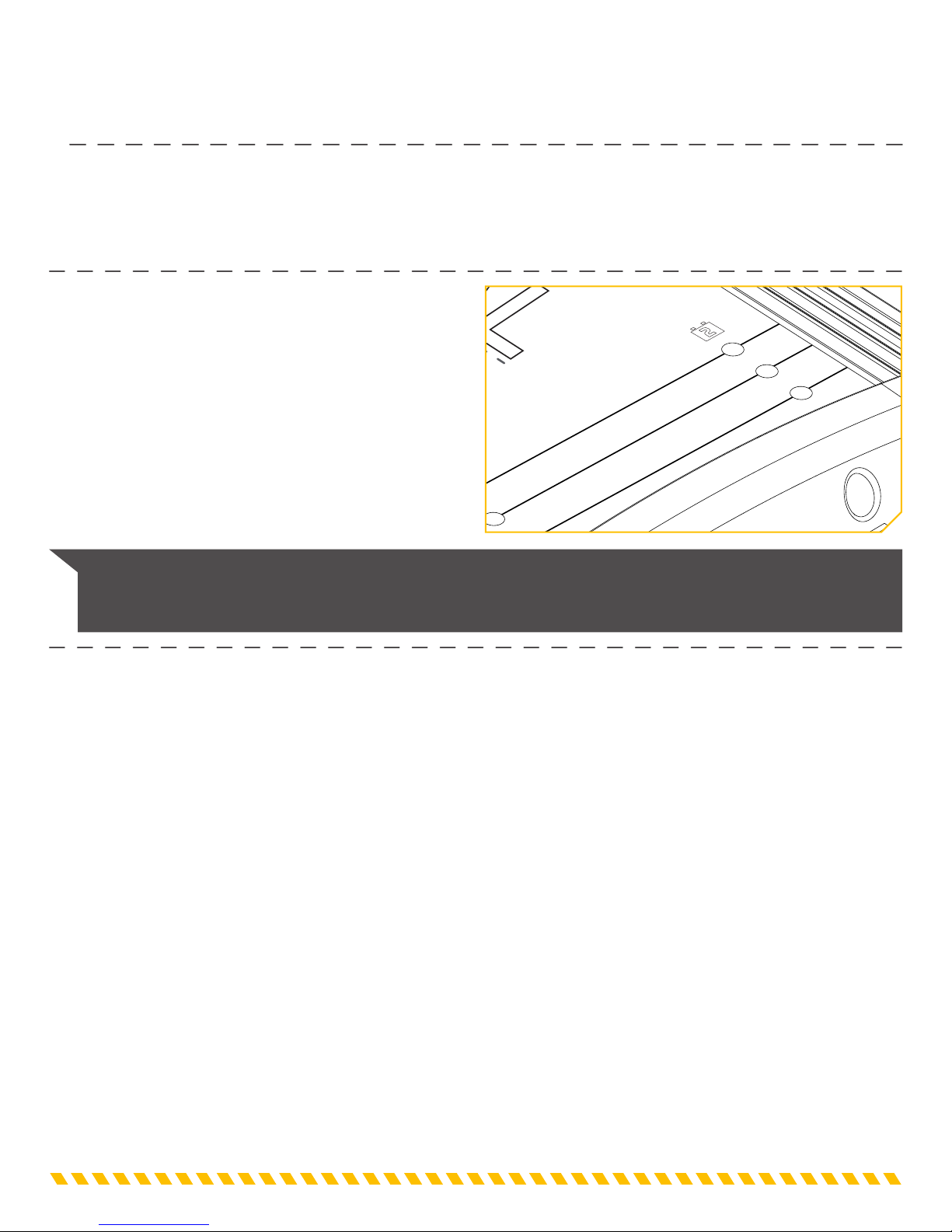
NOTE: Specifications subject to change without notice. This diagram is for reference only and may differ from your
actual charger.
Comprehensive LED Display
AC Plug Holder
Digital, Microprocessor-Based Design for:
• Automatic Temperature Compensation
• Automatic, Multi-Stage Charging
Waterproof, shock-resistant,
vibration resistant construction

(Optional Accessory Kit #1820089 - not included)
minnkotamotors.com | 13
©2017 Johnson Outdoors Marine Electronics, Inc.
OPTIONAL INSTALLATION
Item /
Assembly Part # Description Qty.
1✖15 EXTENSION BLE 1
2✖WIRE SPLICE 2
3✖ADHIVE HEAT SHRINK 2
✖This part is included in an assembly and cannot be ordered individually.
INSTALLING THE MK-EC EXTENSION CABLE ACCESSORY
The Minn Kota Battery Charger Output Extension Cables are ideal for extending charger output cables that do not reach bow,
center or transom battery compartments. Featuring easy installation with waterproof adhesive heat shrink for use in saltwater
environments. Each conductor is fused for protection against accidental short circuits.
INSTALLATION PARTS LIST
1
3
2
• Wire Cutters
• Wire Strippers
• Crimpers
• Heat Gun
TOOLS AND RESOURCES REQUIRED
INSTALLATION
a. Remove AC power from your charger and
disconnect the charger from ALL batteries.
b. Open the door or hatch of the compartment
and allow it to air out for 15 minutes. This
allows any gasses that have accumulated in the
compartment to escape.
c. Find the charger output cable you would like to
extend and use the wire cutters to cut the red or
white (positive) and black (negative) wires before
the fuse holders.
1
NOTE: Some output cables will have a
temperature sensor in the cable covered by heat
shrink. You must cut above the temperature
sensor to avoid damaging the sensor.
Temperature Sensor
Cut Here

14 | minnkotamotors.com ©2017 Johnson Outdoors Marine Electronics, Inc.
OPTIONAL INSTALLATION
d. Remove the loose pieces of insulation from the ends of the extension cable wires and crimp the black (negative) wire
into the Wire Splice connector using the crimpers.
e. Strip the charger output cable wires 3/8” if they are 12AWG. Strip the output wires 3/4” if they are 14AWG or
16AWG.
f. Place one of the Adhesive Heat Shrinks over the Wire Splice and onto the black extension cable wire.
g. For 12AWG wire, insert the black charger output cable into the Wire Splice and crimp using the crimpers. For 14AWG
or 16AWG wire, fold the stripped black charger output wire in half before inserting and crimping the wire.
h. Center the Adhesive Heat Shrink over the Wire Splice. Using the heat gun, warm the Adhesive Heat Shrink until it
seals the connection.
i. Repeat steps e through h for connecting the red or white (positive) wires to the Wire Splice.
j. Prepare each battery in advance by cleaning off dirt, oil, battery corrosion, etc. Use a water and baking soda solution
for cleaning corrosion. Wipe using a dry cloth.
k. Route the output extension cable away from sharp objects. Do not remove the fuse holders, since fuses are located
on both the positive and negative wires for protection in case of a short circuit.
l. Now connect the extension cable to the battery. Be sure to connect the black (negative -) ring terminal to the
negative battery post and connect the red (positive +) ring terminal to the positive battery post.
2
Red (Positive +) Wire
White (Positive +) Wire
White or Red
(Positive +) Wire
Extension Cable
Charger Output Cable
Do not cut wires near
temperature sensor
Heat Shrink
Wire Slice Connector
Black (Negative -) Wire
Black (Negative -) Wire
Black (Negative -) Wire
To Battery

minnkotamotors.com | 15
©2017 Johnson Outdoors Marine Electronics, Inc.
Operating instructiOns
Operating instructiOns
OVERVIEW
This is a high performance battery charger that has the ability to properly and safely work with LEAD-ACID: FLOODED/WET
CELL, MAINTENANCE FREE, and AGM/STARVED ELECTROLYTE batteries only. It is important to read and understand how
to properly use the battery charger before charging batteries.
Each output bank is independent and isolated from one another and the AC input. The Minn Kota charger can charge
independent batteries or combinations of batteries hooked in series or parallel without disconnecting the batteries from any
switches or wires / straps joining the batteries.
12v Battery 12v Battery
12v Battery
12v Battery 12v Battery 12v Battery
12v Battery 12v Battery 12v Battery 12v Battery
Single Bank
Battery Charger
Two Bank
Battery Charger
Four Bank
Battery Charger
Optional
Jumper
Wires
NOTE: If batteries are connected in a series with jumper wires, those wires can be left in place during charging.
Black-
Black- Black- Black-
Red+
Red+ Red+ Red+
Black- Black-Red+ Red+
Black- Black- Black- Black-Red+ Red+ Red+ Red+
120V AC Input
120V AC Input
120V AC Input
120V AC Input
Optional
Jumper
Wires
Optional
Jumper
Wires
Optional
Jumper
Wires
Optional
Jumper
Wires
Optional
Jumper Wires
Three Bank
Battery Charger
16 | minnkotamotors.com ©2017 Johnson Outdoors Marine Electronics, Inc.
OPERATING INSTRUCTIONS
GENERAL OPERATION
After the AC cord on the charger is plugged in and a battery is connected to the output cable correctly, the Yellow LED will turn
on. After 4 seconds the charger will begin charging the battery. The 4 second delay is added to allow the user to establish a
good connection before the charger output is turned on. This will help prevent unwanted sparks during battery connections.
NOTE: If a RED LED is on, reference the Troubleshooting Section of this manual to determine the reason and take the
necessary corrective action to remedy the situation. If you are unable to remedy the situation and need help, call the
Minn Kota Service Department at 1.800.227.6433 and a technical support representative will be happy to assist you.
INDICATOR LEDS
Each bank has the following LEDs:
• A solid RED LED indicates there is an issue with the
battery connection.
• A flashing RED LED indicates an error. See the
Troubleshooting section of this manual.
• A YELLOW LED indicates the progress of charging.
• A flashing GREEN LED indicates battery is fully charged, in
Maintenance Mode and ready to use.
• A solid GREEN LED indicates battery is fully charged, in
long term Maintenance Mode and ready to use.
CHARGING (1-10A)
FULL CHARGE (0-1A)
CHECK CONNECTION
2 Bank • 10 Amps per Bank • 20 Amps Total
Ignition Protected • Waterproof Construction*
For Use with 12 Volt/6 Cell Batteries
that are Flooded/Wet Cell, Maintenance Free
or Starved Electrolyte (AGM) Only
*MANUFACTURER’S ENCLOSURE RATING
ON-BOARD BATTERY CHARGER
MK220D
minnkotamotors.com | 17
©2017 Johnson Outdoors Marine Electronics, Inc.
OPERATING INSTRUCTIONS
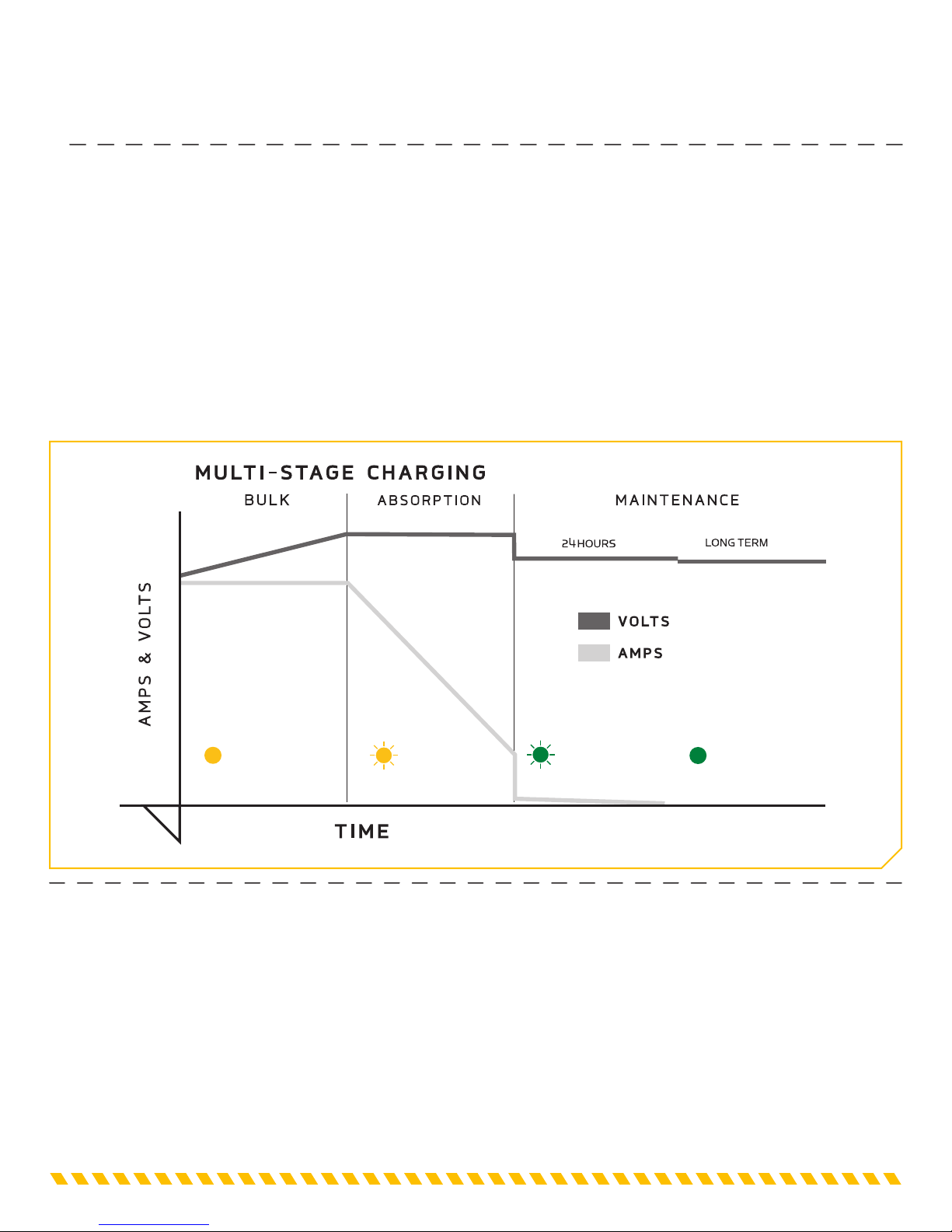
MULTI-STAGE CHARGING
Minn Kota’s Multi-Stage Charging delivers a fast, precise charge profile by automatically controlling current and voltage without
overcharging your batteries.
Bulk: During this stage, the charger delivers full current until the battery reaches ~75% charge. A YELLOW LED is lit to indicate
the battery is charging in the Bulk Mode.
Absorption: The charging current tapers down while the battery voltage is held at 14.4V (at 77° F). A flashing YELLOW LED
indicates the battery is charging in the Absorption Mode.
Maintenance: When the battery reaches full charge, the charger voltage is reduced. A flashing GREEN LED is lit to indicate
the battery is in Maintenance Mode and ready to use. After 24 hours, the charger automatically turns off and a steady GREEN
LED is lit to indicate the battery is in long term Maintenance Mode and ready to use. The charger will automatically resume
charging when the battery voltage drops below 12.6V.
Charging Full Charge
Charging Full Charge
Yellow LED Flashing Yellow LED Flashing Green LED Green LED
(THREE STAGE CHARGER)
18 | minnkotamotors.com ©2017 Johnson Outdoors Marine Electronics, Inc.
OPERATING INSTRUCTIONS
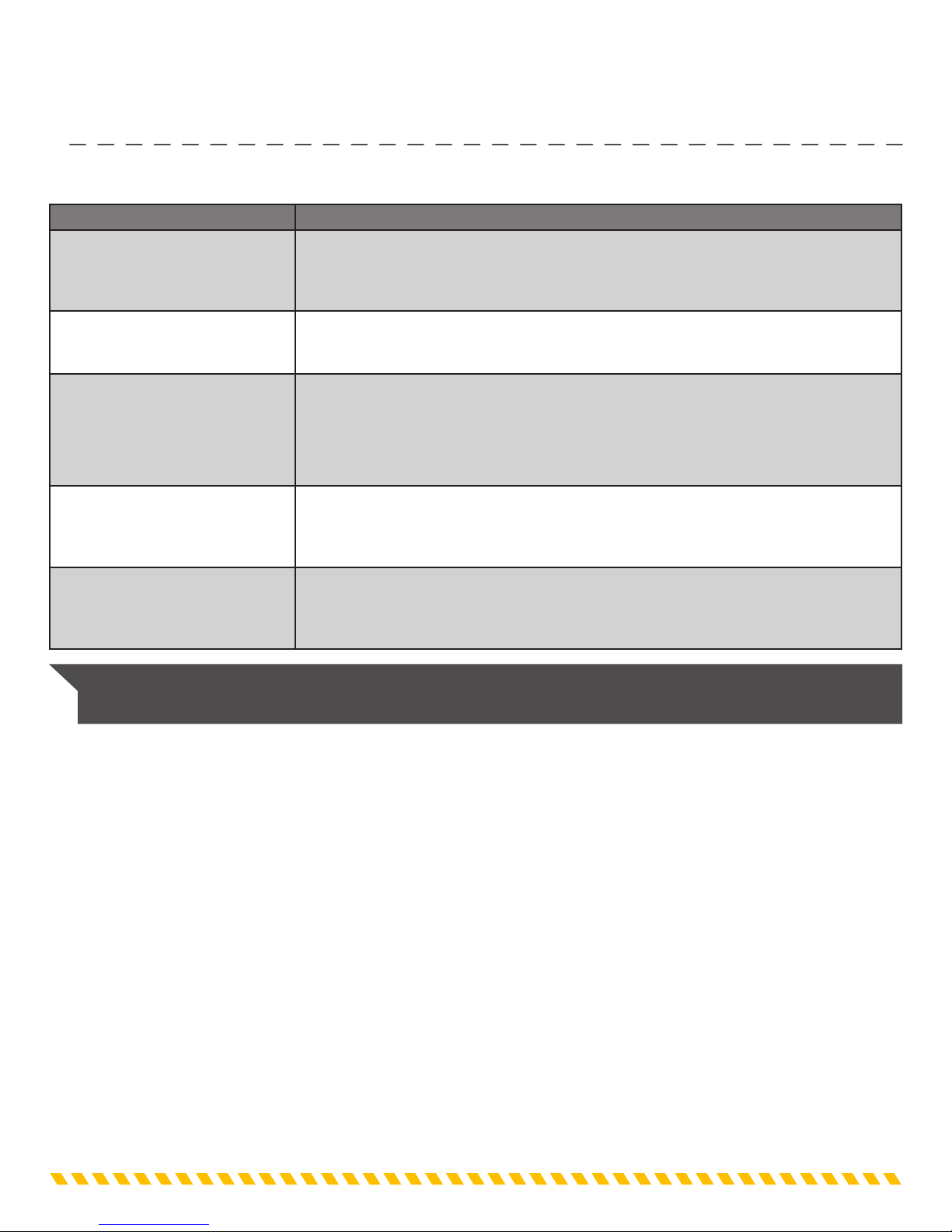
TROUBLESHOOTING
Error Condition Solution
RED LED is lit.
Check connection.
• Check polarity of leads to battery.
• Check connections to battery and fuses in output cord.
• Check voltage at battery. The bank will not charge a battery below 4 volts or above 18 volts.
• If still not working, call the Minn Kota Service Department at 1-800-227-6433.
RED LED is flashing.
Temperature sensor error.
• Reset the charger by unplugging the AC cord. Wait for all LEDs to turn off.
• Plug in the AC cord.
• If still not working, call the Minn Kota Service Department at 1-800-227-6433.
RED LED & GREEN LED is flashing.
Battery may be damaged.
• Check to make sure there are not any loads on the battery.
• Check the fluid in the battery and add fluid if necessary.
• If the battery voltage does not rise above 10.5 volts in 3 hours, or if the absorption voltage does
not increase to 14.4 volts (at 77F), the charger bank will shut down and will not charge. The battery
should be tested.
• If still not working, call the Minn Kota Service Department at 1-800-227-6433.
Indicator LEDs will not illumine.
• Check the AC power at the outlet.
• Make sure the GFCI(Ground Fault Circuit Interrupter) for the outlet has not tripped.
• If an extension cord is being used, check the AC power at the end of the extension cord.
• If still not working, call the Minn Kota Service Department at 1-800-227-6433.
Charger powers up and then turns off.
• If an extension cord is being used, check the AC power at the end of the extension cord.
• Extension cord AWG is too small - refer to chart in the Safety Instructions section.
• Very low AC voltage is applied to the charger.
• If still not working, call the Minn Kota Service Department at 1-800-227-6433.
NOTE: For all other malfunctions, please contact Custom Service. Our customer service representatives are available
Monday – Friday between 7:00 a.m. – 4:30 p.m. CST at 800-227-6433.

minnkotamotors.com | 19
©2017 Johnson Outdoors Marine Electronics, Inc.
MAINTENANCE INSTRUCTIONS
GENERAL MAINTENANCE
• Check battery charger for dirt, oil, battery corrosion, etc. Use a water and baking soda solution for cleaning corrosion. Wipe
clean using a dry cloth.
• Check clips for dirt, oil, and battery corrosion; then disconnect from battery posts and clean as necessary with water and
baking soda solution and dry with a clean cloth.
• When the charger is not in use, coil the power cord and output cord to prevent damage.
• When storing the battery charger, store in a clean dry area.
• If power cord or plug becomes damaged, you may contact the Minn Kota Service Repair Department for service repair
information. Otherwise, dispose of the battery charger in compliance with local law. Damaged cords and plugs can cause
electric shock or electrocution.
ELECTRICAL SPECIFICATIONS
Model Part No. System Volts Output per Bank
(amps) Total Output
(amps) Input Current
(120VAC, 60Hz) Input Power
(120VAC, 60Hz)
MK106D 1821065 12 6 6 1A 100W
MK210D 1822105 12 / 24 510 2.5A 200W
MK220D 1822205 12 / 24 10 20 4.4A 470W
MK315D 1823155 12 / 24 / 36 515 2.7A 270W
MK330D 1823305 12 / 24 / 36 10 30 5.2A 500W
MK330DS 1823304 12 / 24 / 36 10 30 5.2A 500W
MK440D 1824405 12 / 24 / 36 / 48 10 40 7A 620W
MECHANICAL SPECIFICATIONS
Model Part No. Banks Input Cable Output Cable Size L x W x H Weight (lbs)
MK106D 1821065 118AWG - 6" 16AWG - 6’ 8-3/4” X 4-3/4” X 3 4.5
MK210D 1822105 218AWG - 6" 16AWG - 6’ 11-1/2” X 7-1/2 X 4” 11
MK220D 1822205 218AWG - 6’ 16AWG - 6’ 13-1/2” X 7-1/2” X 4” 15
MK315D 1823155 318AWG - 6’ 16AWG - 6’ 12-1/2” X 7-1/2” X 4” 14
MK330D 1823305 318AWG - 6’ 16AWG - 6’ 16-1/4” X 7-1/2” X 4” 20
MK330DS 1823304 318AWG - 8.5’ 16AWG - 6’ 16-1/4” X 7-1/2” X 4” 20
MK440D 1824405 418AWG - 6’ 16AWG - 6’ 11-34” X 6-3/4” X 8” 22.5
DANGER
Damaged cords and plugs can cause electric shock or electrocution.
20 | minnkotamotors.com ©2017 Johnson Outdoors Marine Electronics, Inc.
GENERAL MAINTENANCE
FREQUENTLY ASKED QUESTIONS
1. Can I charge two batteries on one charger bank?
• Yes, but it is not recommended. It takes double the amount of time to charge two batteries and could result in an error being
displayed if the batteries take too long to charge.
2. Do I need to disconnect the series or parallel battery connection(s) when using Minn Kota chargers?
• No, the battery jumper wire(s) can remain in place for both types of wiring.
INLINE FUSE
The output cord has an inline fuse on the RED end. The fuse serves as protection from surges and short circuits caused
by a damaged charger output cable. If a fuse blows, replace it with a 30 amp ATC 32V automotive fuse. Improper battery
connections will normally not cause a fuse to blow since this is handled by the internal circuitry of the charger.
3. How warm do Minn Kota battery chargers get?
• The Minn Kota battery chargers can reach 150° F. They may get warm in an enclosed area. The maximum recommended
room temperature for charging batteries is 122° F. If the charger seems to get “hot,” try opening a hatch to help cool the
charger. When the charger is hot, the output current will drop to protect the charger and the battery.
4. What size fuses are used on Minn Kota battery chargers?
• Chargers with a yellow fuse holder use a 30 amp AGX 32V automotive fuse. An AGC can be used but may not fit as well as
the AGX. Chargers with a red fuse holder use a 30 amp ATC 32V automotive fuse.
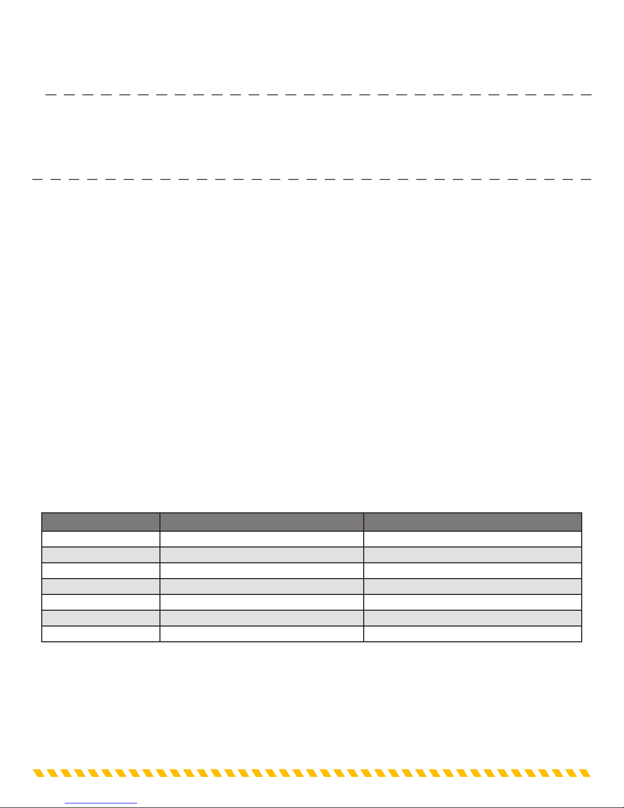
5. What Batteries can be charged by a Minn Kota charger?
• Minn Kota Chargers can charge 12 volt 6 cell lead-acid batteries. Minn Kota D Series Chargers and Minn Kota
Portable Chargers work well with LEAD-ACID: FLOODED/WET CELL, MAINTENANCE FREE, and AGM/STARVED
ELECTROLYTE. Minn Kota PC series Chargers have optimized charging for LEAD-ACID: FLOODED/WET CELL,
MAINTENANCE FREE, GEL and AGM/STARVED ELECTROLYTE battery types. You should verify with your Battery’s
Manufacturer the maximum Amp input for your Battery. The Amp Hour or AH rating for your battery should be in the range
indicated below for the per bank amp output of the battery charger selected.
Model Battery Charger Output Per Bank Battery Amp Hour Rating
MK106D 6 AMPS 24-125 AH
MK210D 5 AMPS 20-125 AH
MK220D 10 AMPS 40-125 AH
MK315D 5 AMPS 20-125 AH
MK330D 10 AMPS 40-125 AH
MK330DS 10 AMPS 40-125 AH
MK440D 10 AMPS 40-125 AH
This manual suits for next models
5
Table of contents
Languages:


