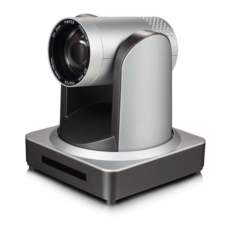
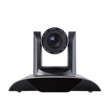
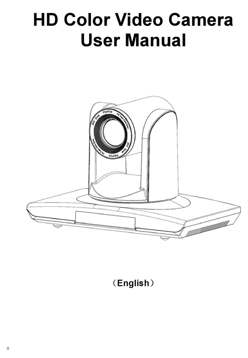
minrray UV910 User manual

0
Minrray UV910 (VHD-A910)
User Manual
www.Minrray.com | 1 800 486-5276

1
Preface:
Thanks for using our HD video conference camera
The manual introduce the function, installation and operation of the HD camera.
Prior to installation and usage, please read the manual thoroughly.
Warning
This product can be only used in specified range in order to avoid to any damage or
danger.
Don’t expose the camera to rain or moisture place.
Don’t remove the cover to reduce the risk of electric shock. Refer servicing to
qualified personnel.
Never operate the camera under unqualified temperature, humidity and power
supply.
Only use the replacement parts recommended by us.
Please use the soft cloth to clean the dome. Use neuter cleanser if bad smeared. No
use the strong or corrosive cleanser avoiding scuffing.
Be careful of moving, never press the drive parts heavily avoiding camera trouble
Notes
Electromagnetic fields at the specific frequency may affect the image quality.

2
Contents
1. Notes………………………………………………………….3
2. Main Feature………………………………………………...4
3. Supplied Accessory………………………………………….5
4. Camera Interface Explanation…………...............................6
5. Remote Controller…………………………………………..7
6. Camera Function…………………………………………….8
7. Bottom Dial Switch………………………………………….9
8. Connection……………………………………………………10
9. VISCA RS-232 Pin Spcs……………………………………..12
10. Installation…………………………………………………...13
11. Operation…………………………………………………….15
12. Menu Setting…………………………………………………30
13. Maintains and Trouble Shooting……………………………35
14. Specification…………………………………………………..36
15. Dimension……………………………………………………..38

3
Notes:
Electric Safety
Installation and operation much accord with electric safety standard.
Caution to transport
Avoid stress, vibration and soakage in transport, storage and installation.
Polarity of power supply
The power supply of the product is 12VDC, the max electrical current is 2A. Polarity of the
power supply is as following drawing
Careful of installation
Never move the camera by seizing the camera head. Don’t rotate the camera head by hand,
otherwise, mechanical trouble will occurred.
1. This series item much put on the smooth desk or platform and it can not be installed slantways
2. If the camera is installed on TV or PC, the base can be fixed by four double-sided adhesive tray.
3. Don’t apply in corrosive liquid, gas or solid environment to avoid the cover corrosive which is made up of
organic material.
4. To make sure no obstacle in rotation range.
5. Never power on before installation is not completed
Don’t dispatch discretionarily
This series items have no parts that user can repair by themselves. Don’t disassemble the
camera yourself, otherwise, such damage by that does not belong to the warranty scope.

4
Main Features:
Real High Definition Video
With 1/2.5 inch, 2.7 million pixel high quality HD CMOS transducer, to achieve 1920x1080
super high resolution video.
10x optical zoom
Fast, accurate and stable auto focus lens, 10x optical zoom; F1.8-2.2 mechanical shutter.
Wide range, high speed and low noise Pan/Tilt rotation
Step motor driving, smooth rotation and user friendly without dithering. Moving to the
appointed position quickly and accurately, meanwhile, shooting large area.
High definition multiple video output format
Offer 1080p, 1080i, 720p HD video format and can video out the HD analog signal and digital
signal simultaneously from the interface of the YPbPr, HDMI, HD-SDI
High quality video transfer by HD-SDI
Equipped with HD-SDI terminal interface(SMPTE292M), to support long distance, high quality HD
video transfer.
High quality image output by high definition multi-media interface
Digital high definition multi-media interface, digital high definition video signal output, which
is connected to the HD display equipment by cable directly.
RS-232Cremote controller( VISCA protocol)
RS-232C(VISCA protocol) interface: All setting of the camera and Pan/Tilt/Zoom can be
remote high speed communication controlled.
10 preset position
10 preset position, preset pan, tilt, zoom, focus position, exposal mode and white balance.
Preset data never lost when power is off.
In-ceiling installation function
The camera can be installed in ceiling from structure design. By the serial command, camera
image can flip in pan and tilt direction. And the setting can be saved after power off.
Multi-function remote controller
Equipped easy and convenience remote controller. Except the basic setting and the control of
Pan/Tilt/ Zoom, it can also set the relative parameters of camera by the remote controller.
OSD menu in Chinese and English
With Chinese-English OSD menu and by the menu the users can set the camera exposure
parameter, change the video format and check the current status.

5
Supplied Accessories
When you unpack, check that all the supplied accessories are included:
Camera…………………………...1
AC power adaptor………………..1
AC power cable…………………...1
Remote controller………………...1
User manual………………………1
Double-side glue shim………..…4

6
Camera Interface Explanation
1. Lens
2. Main Camera Base
3. Remote Controller Sensor
4. Remote Controller Receiver
5. RS232 controller serial interface
6. CVBS SD Compound Video Output Interface (not available now)
7. HD-SDI High Definition Serial Digital Signal interface
8. HDMI High Definition Multi-Media Signal Interface
9. YPbPr high definition components video signal
10. DC12V Input Power Supply Jack
11. Power Switch, On is open, OFF is close
12. Power indicator light (red)
13. Bottom dial Switch
14. Tripod screw hole
15. Installation Orientation Hole

7
Remote Controller:
Definition of IR controller
①Number Key
②* Key
③#Key
Run Preset: press 0-9 number key,
clear preset: press###to clear all preset
④Zoom control key
Zoom +: lens near
Zoom -: lens far
⑤Focus control key
Focus+:from near to far
Focus-:from far to near
⑥HD video output mode change key
* # F1:HD video output mode 1080i/60
* # F2: HD video output mode 720p/60
* # F3: HD video output mode 720p/30
* # F4:HD video output mode 1080p/30
*+#+ :HD video output mode 1080p/25
⑦set preset
set preset:
*SET PRESET* + number key (0-9)
clear preset
“CLEAR PRESET”+number(0-9): clear the
relative preset
###:Clear all preset
⑧pan/tilt control key
press key:up
press key:Down
press key:Left
press key:Right
press “HOME” key:Return to the middle position
⑨BLC control key
BLC ON: open the BLC
BLC OFF: close the BLC
⑩Menu setting
Open or close the OSD menu

8
Camera Function
It has 2 kinds of working modes.
Two working modes can be controlled by IR remote controller and VISCA serial interface
command.
1. Normal working mode, camera can be controlled by remote controller and serial
interface command.
2. Lens parameter adjustment mode, it can adjust the lens parameter, but normally
user rarely use.
●Super wide visual angle
With selectable wide angle lens of more than 70°, for big, medium and small conference
room.
●10x optical zoom
With 10x optical zoom lens and wide angle lens, absolutely accord with all kinds of meeting
room application. Users can use the IR remote or VISCA RS232 to control the zoom
●Focus
Auto focus mode and manual focus mode. It can be controlled by IR remote controller and
VISCA command.
1, Auto Focus
2, Manual Focus
●Iris
1, Auto iris mode
2, Manual iris mode(Only control by serial interface command)
●Electric Shutter
Auto electric shutter
●Black light compensation
Open/close BLC can be realized by remote controller and VISCA command.
●White Balance
Multiple white balance modes can be set, including:
Auto, custom, manual, daylight, cloudy, shade, FL white, FL normal, FL daynight, and light
bulb.
●Multi-control mode
1, by IR remote controller
2, by RS-232 serial interface, standard VISCA command

9
●Multi-SD and HD video output
1, Standard definition video output: CVBS SD compound video signal output (unavailable
now)
2, High definition digital video signal: HD-SDI high definition serial digital signal interface
output uncompressed HD digital signal.
3, HDMI: High Definition digital video signal: Digital HD multi-media output uncompressed
digital video signal.
4, High Definition analog video signal: YPbPr high definition components video signal
interface output high definition components analog video signal.
Dial Switch of bottom
SW-1
SW-
2
Modes
1
OFF
OFF
Normal Working Mode
2
ON
OFF
Software Upgrade Mode
3
OFF
ON
Factory debug mode
4
ON
ON
None

10
Connection
HD camera Interface explanation:
●Control interface RS-232
RS232 serial interface, wiring is standard VISCA cable, one of the linker is 8pin mini DIN(1),
the other is RS232C 9 core square linker ( DB-9, DB-25), which connect with computer or
conference TV terminal.
●Standard definition video signal CVBS
SD compound video signal (unavailable now)
●High Definition Digital Video Signal HD-SDI
HD-SDI serial digital signal interface can transmit long distance and high quality high
definition video, image will never lost.

11
●HDMI High Definition Multi-Media Digital Signal
High Definition Multi-Media Digital Signal interface output High Definition digital video signal
●High Definition Component Video Signal YPbPr
HD component video signal interface output high definition component analog video signal.
●Power supply interface DC12V
Input power supply is adopted external adapter to offer 12V/2A DC.
BNC polarity of power supply is shown as following external adapter:
●Power supply switch
On is open, OFF is close
●Power Indicator Light (Red)
Power supply switch is “ON”: indicator light is open, voltage is normal; otherwise, indicator
light is closed, no power or voltage is abnormal.

12
VISCA RS-232 Pin Spcs
HD camera Windows DB-9
1.DTR 1.CD
2.DSR 2.RXD
3.TXD 3.TXD
4.GND 4.DTR
5.RXD 5.GND
6.GND 6.DSR
7. 7.RTS
8.NC 8.CTS
9.RI
HD camera Windows DB-25
1.DTR 1.FG
2.DSR 2.TXD
3.TXD 3.RXD
4.GND 4.RTS
5.RXD 5.CTS
6.GND 6.DSR
7. 7.GND
8.NC
20.DTR
HD camera Mini DIN
1.DTR 1.DTR
2.DSR 2.DSR
3.TXD 3.TXD
4.GND 4.GND
5.RXD 5.RXD
6.GND 6.GND
7. 7.NC
8.NC 8.NC
No.
Function
1
DTR
2
DSR
3
TXD
4
GND
5
RXD
6
GND
7
8
NC

13
Installation
Notes
Do not grasp the camera head when carring the camera.
Do not turn the camera head manually. Doing so will result in the camera malfunction.
Installation and Application
There are different installations for different environment:
1, on desk
2, on terminal equipment
3, on the tripod
4, hoisting by hoisting stents
Be careful when install
This series item can not be put on shake object to avoid bad image effect, and must put on the
smooth desk or platform, and it can not be installed slantways;
Install the batteries
Open the battery lid at the back of the remote controller, install battery properly, and then close
the lid.
Note the polarity of battery

14
Notes on use of the Remote Controller
If the remote controller doesn’t work properly, change the batteries.
If there are objects between the remote controller and the sense for the remote controller on the
unit, the unit may not function properly, so point the remote controller directly at the sensors on
the front of back of the unit when operating it.

15
Operation
!Boot-Strap
1, Check whether the power wiring is corrects.
2, Set the power supply switch “ON” at the back of camera, power indicator light is red.
3, Camera initializes after 5 seconds: Rotate to the right limit, move to the down limit; Then turn
left, motor stops when horizontal and vertical rotation is in the middle, camera lens will move to
the wide angel position. Initialization finishes
4, when initialization finishes, HD video interface output video signal. Default signal is
1920x1080/60i
5, Default control mode is “Mode 0”
!Control Mode
HD color video camera has two kinds of control ways: controller command and COM
command. Which kind of command the HD camera react depends on the work mode of the
camera, the camera has four work mode; mode 0, mode 1, mode 2, mode 3.
The instruction of control way and the work mode of HD camera are as follows:
Mode 0: this is default mode
Camera can receive and execute the COM command. User can use COM port to control the
camera’s presets, pan/tilt rotation and so on.
User can use our remote controller to control camera’s rotate, focus, presets, BLC and so on.
Mode 1
Camera can receive but won’t execute the COM command, so user can’t use COM port to control
the camera under this work mode.
User can use our remote controller to control camera’s rotate, focus, presets, BLC and so on.
Mode 2
Camera can receive and execute the COM command.
User can use our remote controller to control camera’s rotate, focus, presets, BLC and so on.
The IR command of our remote controller can only be executed locally, and can not be passed to
the terminal.
Mode 3:
Can only use our remote controller to control under this work.
User can set the parameter of camera, also control the camera’s rotate, zoom, BLC and so on.
As the parameter setting is also finished by number keys, so the presets operation can not be
done in mode 3..
Mode setting:
1 Setting mode by special terminal controller:
As for the special terminal controller, no matter which mode camera is in, only if camera is in the
power-on status, camera can be set to mode 0,mode 1, mode 2, mode 3.
Mode 0: press *+#+0

16
Mode 1: press *+#+1
Mode 2: press *+#+2
Mode 3: press *+#+3
2 The working mode of the camera can also be set by terminal COM, the relative command can
be seen in the COM command list.
3 Setting camera working mode by camera controller
Note: By the camera controller, the camera can only be set to mode 0 and mode 3. And only in
mode 3, the camera parameter can be set. The camera can not be transferred to other mode.
Mode 0: *+#+0
Mode 3: *+#+3
For the convenience of video user, camera working mode will not be memorized automatically,
and every time there will be mode 0, the default mode after power-on.
IR Remote Controller
After power on, the camera can receive and execute IR remote command. By IR remote
controller can control the preset, Pan/Tilt rotation etc.
Key-press note:
1, the key combination in this manual is operated based on the sequence, take one example:
“ *+#+ F1” means press “*” first, then press “#”, finally press “F1”.
1、PAN/TITL OPERATION
Up: press
Down: press
Left: press
Right: press
press“home”key: return to middle position.
There are three grades for speed level: when zoom is 1-4 the speed is fast; when zoom is 5-7 the
speed is middle; when zoom is 7-10 the speed is low.
Press up, down, left, right key for long time, the camera can keep moving continuously, and stop
when you release.

17
2、ZOOM OPERATION (put on reservation)
ZOOM OUT: press “ZOOM -“ buttom
ZOOM IN: press “ZOOM +” button
Press these two keys for long time, zoom in and out can be executed continuously, and stop
when you release.
3、Focus control
4、BLC setting
BLC ON: open BLC
BLC OFF: close BLC
5、SETTING PRESET

18
Pressing “SET PRESET” key and then press any number of 0-9 to set relative preset. (Notes:
Total 10 Preset)
6、Clear Preset
Press “CLEAR PRESET” and press any number of 0-9 to clean relative preset.
Press “#” three times to cancel all preset.

19
7、Run Preset
Press any number of 0-9 to run relative preset.
If there is no preset to relative number, then invalid..
8、Video Output Mode
Press * # F1: 1080i/60
Press * # F2: 720p/60
Press * # F3: 720p/30
Press * # F4: 1080p/30
Press * # : 1080p/25
Other manuals for UV910
1
Table of contents
Other minrray IP Camera manuals

minrray
minrray uv83 User manual

minrray
minrray UV510A-10-ST User manual

minrray
minrray UV910 User manual

minrray
minrray UV830 Series User manual

minrray
minrray UV950 User manual

minrray
minrray UV-J1220 User manual

minrray
minrray UV820 User manual

minrray
minrray UV950A User manual

minrray
minrray UV850 User manual