Minusforty 13-USGR-F2 User manual

Model:
Serial Number:
Date of Purchase:
To better help you obtain assistance or service should you ever need it, write down the
following information about the product. This information is on the identification label
located on the left hand inside wall of the cabinet. We advise you to keep this Owners
Manual and sales slip in your possession.
Owners Manual
Payment Enabled
Glass Door Refrigerators
230V 50Hz
Single Door Models (with Smartlock and POS Terminal)
13-USGR-F2, 19-USGR-F2, 22-USGR-F2
13-USGR-L2, 19-USGR-L2, 22-USGR-L2
MNL_R290 USGR-F2-L2 230V POS_EN20210923
30 Armstrong Ave. Georgetown, Ontario Canada L7G 4R9
30 Armstrong Avenue
Georgetown, Ontario
Canada L7G 4R9
Tel: +1.905.702.1441
Fax: +1.905.702.1442
email: info@minusforty.com
web: minusforty.com
tel +1.905.702.1441 ·fax +1.905.702.1442 ·MINUSFORTY.com

ATTENTION
Heat Insulation Material Polyurethane (PU) Foam
with Carbon Dioxide
Do not put the unit in with regular waste.
Please check your obligations in accordance
with the national WEEE provisions and the
local WEEE disposals partner. Ensure the
piping is not damaged in the process.
ATTENTION
Heat Insulation Material Polyurethane (PU) Foam
with Carbon Dioxide
Do not put the unit in with regular waste.
Please check your obligations in accordance
with the national WEEE provisions and the
local WEEE disposal partner. Ensure the
piping is not damaged in the process.

24
WIRING DIAGRAM (USGR-F2 , USGR-L2 MODELS WITH SMARTLOCK)
WARNING
THIS UNIT IS CHARGED WITH PROPANE REFRIGERANT. PRO-
PANE IS AN EXTREMELY FLAMMABLE AND EXPLOSIVE GAS.
PLEASE READ CAREFULLY THIS MANUAL/GUIDE AND FOL-
LOW ALL SAFETY PRECAUTIONS CONTAINED HEREIN TO RE-
DUCE A RISK OF FIRE AND/OR EXPLOSION. FAILURE TO
FOLLOW THE SAFETY PRECAUTIONS MAY RESULT IN
SERIOUS INJURY OR DEATH, AND/OR PROPERTY DAMAGE.
CAUTIONARY INSTRUCTIONS FOR UNITS CHARGED WITH
PROPANE (R290) REFRIGERANT
• WARNING: KEEP CLEAR OF OBSTRUCTION ALL VENTILATION OPENINGS IN
THE APPLIANCE ENCLOSURE OR IN THE STRUCTURE FOR
BUILDING-IN.
• WARNING: DO NOT USE MECHANICAL DEVICES OR OTHER MEANS TO
ACCELERATE THE DEFROSTING PROCESS, OTHER THAN THOSE
RECOMMENDED BY THE MANUFACTURER.
• WARNING: DO NOT DAMAGE THE REFRIGERANT CIRCUIT.
• WARNING: DO NOT USE ELECTRICAL APPLIANCES INSIDE THE FOOD
STORAGE COMPARTMENTS OF THE APPLIANCE, UNLESS THEY
ARE OF THE TYPE RECOMMENDED BY THE MANUFACTURER.
Propane is approved for use as a refrigerant in commercial, self-contained units under limited
use conditions. It can be used in new equipment only, retrofitting is not allowed, with a limited
charge of up to 150 grams (5.3 oz) per refrigeration circuit. Even though this is a small
amount, it still presents a fire/explosion hazard if it leaks out of refrigerant containing parts.
When mixed with air, a flammable propane-air mixture can be created and easily ignited by
sparks, open flames, or hot surfaces. This is particularly true in confined zones. Propane is
heavier than air and tends to settle at lower points.
To mitigate the risk, please follow the precautionary measures as follows:
• Avoid unit installation in areas with open flames (kitchens, repair garages or the like), or
in vicinity of open flames or high surface temperatures.
• Avoid unit installation in confined spaces. Well ventilated areas are preferred. Keep clear
all ventilation openings of obstructions.
• Do not rely on smell to detect potential leaks of propane refrigerant. Propane refrigerant is
a high purity propane gas and does not contain any stanching agent(s). Stanching agents
are typically used in fuel-grade propane and natural gas to detect their presence in air by
relying on smell.
• All repairs must be performed in well ventilated areas.
• To minimize the risk of possible ignition due to incorrect parts or improper service, compo-
nent parts shall be replaced with like components and servicing shall be done by service
personnel authorized by Minus Forty Technologies Corp.
• Do not attempt to modify the unit or remove any functional part(s) from the unit.
• Handle the unit with care to avoid any damage.
• When transporting the unit, all appropriate safety considerations must be considered.
Check with local Department of Transportation for detailed requirements pertaining to
transportation of flammable gasses.

ILLUSTRATION: 13-USGR-F2, 19-USGR-F2, 22-USGR-F2
23

SAFETY PRECAUTIONS
READ ALL INSTRUCTIONS AND SAVE THESE INSTRUCTIONS FOR FU-
TURE REFERENCE.
DO NOT STORE OR USE GASOLINE OR OTHER FLAMMABLE VAPORS
AND LIQUIDS NEAR THIS OR ANY OTHER APPLIANCE.
DO NOT TOUCH COLD SURFACES WITH DAMP OR WET HANDS. SKIN
MAY STICK TO EXTREMELY COLD SURFACES.
DO NOT ALLOW CHILDREN TO CLIMB, HANG OR STAND ON REFRIG-
ERATOR SHELVES.
KEEP FINGERS OUT OF PINCH-POINT AREAS.
DISCONNECT POWER TO THE UNIT PRIOR TO CLEANING OR
REPAIRING.
BEFORE DISCARDING THIS OR ANY OTHER APPLIANCE, REMOVE THE
DOORS OR LIDS TO REDUCE RISK OF CHILD ENTRAPMENT.
WHEN RECYCLING THE UNIT, REFRIGERANTS MUST BE HANDLED IN
ACCORDANCE WITH LOCAL AND NATIONAL REGULATIONS.
NOTICE
OPERATING THE REFRIGERATOR FOR 24 HOURS PRIOR TO LOADING
PRODUCT IS RECOMMENDED
MONITOR REFRIGERATOR TEMPERATURE REGULARLY
WARNING
IN THE EVENT THE POS TERMINAL AND THE ELECTRONIC SAFETY LOCK
HAS LOCKED THE REFRIGERATOR AND DISABLED ACCESS MODE, THE
FOOD IN THE REFRIGERATOR MUST BE INSPECTED TO INSURE ITS
SAFETY AND QUALITY FOR CONSUMPTION.
PARTS LIST: 13-USGR-F2, 19-USGR-F2, 22-USGR-F2
No Description
1 not used
2 not used
3 Door Switch
4 Heater Breaker Seal (Bottom/Top)
5 LED Driver
6 Pilaster
7 Basket
8 Door Assembly (Right or Left Hand)
9 Pilaster Clip
10 Shelf
11 Interior Back Grill
12 Bottom Shelf
13 Torsion Pin
14 Rear Grill
15 Door Handle
16 Leveling Leg
17 Caster
18 Front Bottom Grill
19 Door Top Bracket (Right or Left)
20 Bushing, Nylon
21 Door Bottom Bracket (Right or Left)
22 not used
23 Evaporator Coil
24 Evaporator Tray
25 Evaporator Shroud
26 Evaporator Fan
27 PTC Relay (19/22USG)
28 Run Capacitor (19/22USG)
29 not used
30 Start Capacitor (13USG)
31 Overload Protector (13/19/22USG)
32 Start Relay (13USG)
33 Fan Blade (Condensing Unit)
34 Fan Motor (Condensing Unit)
35 Compressor
36 Filter Drier
37 5 Pole Terminal Block
38 Controller
39 Rocker Switch
22
WARNING
MAKE SURE THE REFRIGERATOR IS DISCONNECTED FROM THE POWER
SUPPLY BEFORE ANY SERVICE. PRESS THE REFRIGERATOR SWITCH TO
THE “OFF” POSITION THEN UNPLUG THE POWER CORD FROM THE ELEC-
TRICAL RECEPTACLE.
ALL SERVICE WORK MUST BE PERFORMED BY CERTIFIED, FACTORY AU-
THORIZED SERVICE PERSONNEL ONLY. COMPONENT PARTS MUST BE
REPLACED WITH LIKE COMPONENTS.
COMMERCIAL USE ONLY. NOT FOR HOUSEHOLD USE.
FOR INDOOR USE ONLY.
No Description
40 Compressor Relay
41 Power Cord-UK / IRELAND
Power Cord - EUROPE
Power Cord - AUS / NZ
42 Nylon Washer
43 Torsion Bar
44 not used
45 not used
46 Condenser Coil
47 Condensate Tray Assembly
48 not used
49 Pressure Relief Ball
50 Heater Breaker Seal (LED)
51 Cabinet LED Strip
52 not used
53 not used
54 Lock Cover
55 Camlock
56 Lock LSIB
57 Lock Release Pin
58 Lock Release Spring
59 Lock
60 Lock Latch
61 Lock Pushbutton
62 not used
63 not used
64 not used
65 not used
66 Backup Battery
67 Battery Holder
68 Wire Cover (POS Terminal)
69 Handle Bracket (POS Terminal)
70 Bezel (POS Terminal)
71 RS-485/232 Converter (POS Terminal)
72 RJ34/RS-232 Harness (POS Terminal)
73 Mounting Base (POS Terminal)
74 Door Wire Harness (POS Terminal)
75 Controller Wire Harness (POS Terminal)
76 LED Driver (POS Terminal)

ILLUSTRATION: 13-USGR-L2, 19-USGR-L2, 22-USGR-L2CONTENTS
21
Warranty
Installation Instructions
Power Requirements
Protective Door Film
Shelf and Basket, Placement and Adjustment
Shelf Load Limit
Operating Instructions
Product Loading
How to Remove the Front Bottom Grill
Temperature Adjustment and Switch Functions
M44D Controller Alarms and Signals
M44D Controller Symbols and Functions
Condenser Cleaning
Cabinet Cleaning
POS Terminal & Electronic Food Safety Lock
General Description
Backup Battery (UPS) Operation
Entrapment Lock Release
Restocking Delay
Accessing / Resetting Alarm Data
Field Testing of the Food Safety Lock
ISD Translight LED Strip Replacement
Interior LED Strip Replacement
Troubleshooting Guide
Parts List (13/19/22-USGR-L2)
Illustration (13/19/22-USGR-L2)
Parts List (13/19/22-USGR-F2)
Illustration (13/19/22-USGR-F2)
Wiring Diagram (USGR-L2, USGR-F2 Models)
1
2
2
2
3
3
3
4
5
5
6
7
8
8 - 9
10
10 - 11
12
13
13
13 - 14
15
16
17
18 - 19
20
21
22
23
24

STANDARD WARRANTY FOR MINUS FORTY®
REFRIGERATION EQUIPMENT AND ACCESSORIES
LIMITED WARRANTY
Minus Forty®Technologies Corp. warrants its products to be free from defect as
to workmanship and materials for a period of twelve (12) months from the time
of delivery.
Minus Forty®Technologies Corp. will at its option either replace or repair any de-
fective parts returned within twelve (12) months of the time of delivery, transpor-
tation charges prepaid, which Minus Forty®Technologies Corp. in its sole
discretion, determines to be defective.
This warranty shall not apply to any products that have been repaired or altered
outside of Minus Forty®Technologies Corp.’s factory or repair facilities if the re-
pairs in the judgement of Minus Forty®Technologies Corp. have affected the reli-
ability or wear of the product and nor does the guarantee apply to any product
which has been subject to misuse, accident or to any product which has not been
maintained pursuant to the instruction of Minus Forty®Technologies Corp.
This warranty does not extend to any consequential damage caused by the failure
of the product under any circumstance and further, Minus Forty®Technologies
Corp. shall not be responsible for damage to the contents of the product or any
economic loss caused by the failure of the product, whether such loss is suffered
by the customer or a third party user of the product or whether the contents are
owned by the customer or a third party user or supplier.
Effective January 1, 1996
1
20
PARTS LIST: 13-USGR-L2, 19-USGR-L2, 22-USGR-L2
No Description
1 Display LED Strip
2 Top Display Assembly
3 Door Switch
4 Heater Breaker Seal (Bottom/Top)
5 LED Driver
6 Pilaster
7 Basket
8 Door Assembly (Right or Left Hand)
9 Pilaster Clip
10 Shelf
11 Interior Back Grill
12 Bottom Shelf
13 Torsion Pin
14 Rear Grill
15 Door Handle
16 Leveling Leg
17 Caster
18 Front Bottom Grill
19 Door Top Bracket (Right or Left)
20 Bushing, Nylon
21 Door Bottom Bracket (Right or Left)
22 not used
23 Evaporator Coil
24 Evaporator Tray
25 Evaporator Shroud
26 Evaporator Fan
27 PTC Relay (19/22USG)
28 Run Capacitor (19/22USG)
29 not used
30 Start Capacitor (13USG)
31 Overload Protector (13/19/22USG)
32 Start Relay (13USG)
33 Fan Blade (Condensing Unit)
34 Fan Motor (Condensing Unit)
35 Compressor
36 Filter Drier
37 5 Pole Terminal Block
38 Controller
39 Rocker Switch
No Description
40 Compressor Relay
41 Power Cord-UK / IRELAND
Power Cord - EUROPE
Power Cord - AUS / NZ
42 Nylon Washer
43 Torsion Bar
44 not used
45 not used
46 Condenser Coil
47 Condensate Tray Assembly
48 not used
49 Pressure Relief Ball
50 Heater Breaker Seal (LED)
51 Cabinet LED Strip
52 not used
53 Heater Breaker Door
54 Lock Cover
55 Camlock
56 Lock Status Indicator Board (LSIB)
57 Lock Release Pin
58 Lock Release Spring
59 Lock
60 Lock Latch
61 Lock Pushbutton
62 not used
63 not used
64 not used
65 not used
66 Backup Battery
67 Battery Holder
68 Wire Cover (POS Terminal)
69 Handle Bracket (POS Terminal)
70 Bezel (POS Terminal)
71 RS-485/232 Converter (POS Terminal)
72 RJ34/RS-232 Harness (POS Terminal)
73 Mounting Base (POS Terminal)
74 Door Wire Harness (POS Terminal)
75 Controller Wire Harness (POS Terminal)
76 LED Driver (POS Terminal)

for online reference go to minusforty.com
TROUBLESHOOTING GUIDE CONT...
Problem Possible Cause Action
Condensation on glass door. • Door not closing properly.
• Room humidity too high.
• Check the spring tension or any
obstruction
• To prevent condensation, room
humidity should be below 55%.
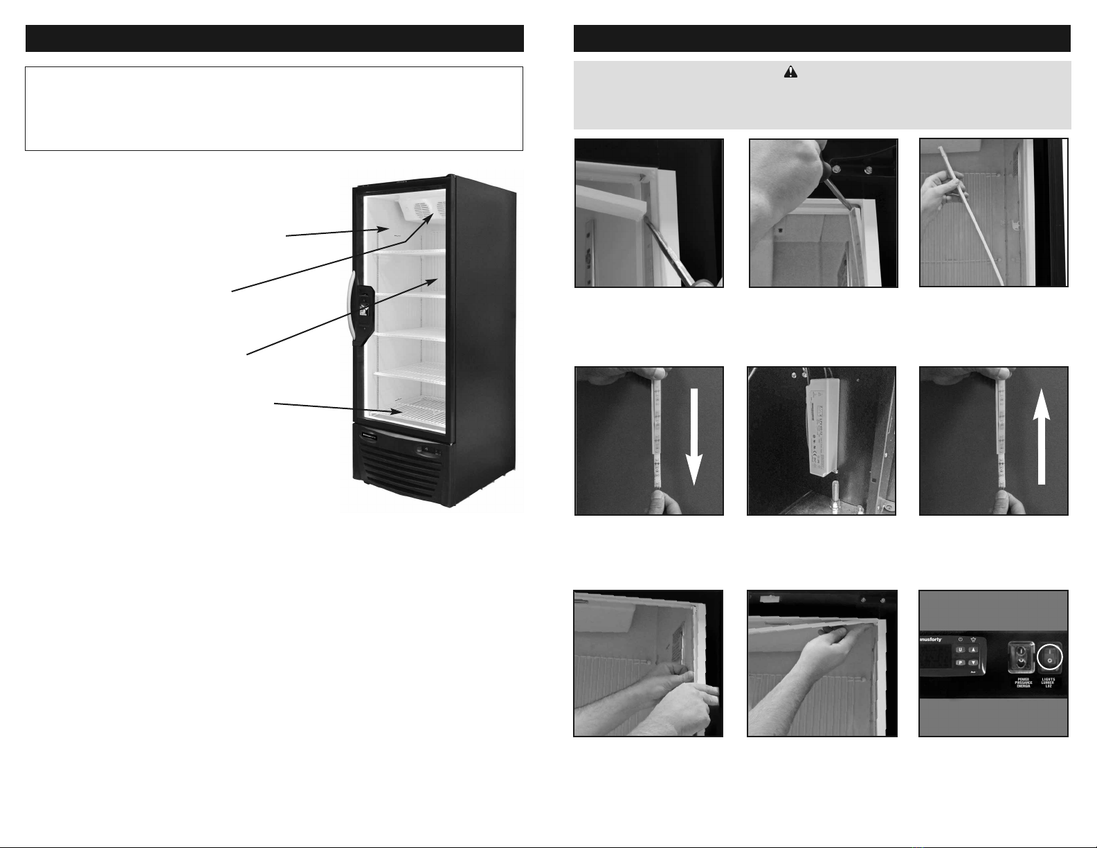
LED strips are not working. • Light switch is off.
• Faulty LED strip. • Check if the light switch is on.
• Replace the LED strip. (See page 17)
Cabinet is noisy. • Part(s) loose
• Tubing vibrating
• Locate and tighten loose part(s).
• Ensure tubing is not in contact with
other tubing or components.
Door does not close tight. • Refrigerator is not leveled.
• Hinges are loose / not adjusted.
• Gasket is out of the groove.
• Level the unit (See page 2).
• Adjust / tighten the hinge screws.
• Check gasket condition. Adjust position
or replace gasket.
Electronic control blank,
flashing, or displaying incorrect
characters.
• Wires disconnected at back of
electronic control. • See actions described in the
controller section (pages 5 - 7)
Evaporator fan does not run. • Fan wire disconnected.
• Door switch not working.
• Check wiring.
• Check door switch.
Alarms on electronic controller. • Various • See “M44D Controller Alarms and
Signals” section (page 6)
WARNING
Make sure the refrigerator is disconnected from the power supply before any service. Press the
refrigerator switch to the “Off” position then unplug the power cords from electrical receptacle.
All service work must be conducted by a certified technician only.
19
2
CABINET LOCATION: This appliance is rated for Climate Class (EN23953), Category 4 (30°C, 55%RH)
and is to be operated in an environment not greater than 30°C (86ºF) and 55% relative humidity.
An air space of at least 6” (15 cm) must be maintained on all sides of the refrigerator. Do not place
refrigerator in direct sunlight; do not place refrigerator under or near heat range or heating vent.
CABINET LEVELING: The refrigerator must be completely leveled side to side and front to back or
slightly tilted front to back but never tilted forward. Once the refrigerator is placed in its final location,
use a carpenter level to level the refrigerator. Proper leveling of the refrigerator is important for the
door closing and water drainage during the defrost cycle. There are two leg levelers in the front that
can be adjusted. First, loosen the nuts using an adjustable wrench. Second, turn levelers counter-clock-
wise to raise the refrigerator, or clockwise to lower, until they reach the leveled position. Lastly, tighten
the nuts again to lock the legs.
INSTALLATION INSTRUCTIONS
• DO NOT USE AN EXTENSION CORD
• DO NOT CUT, REMOVE OR BYPASS THE GROUNDING PRONG FROM THE PLUG
• DO NOT PLUG REFRIGERATOR INTO AN OUTLET CONTROLLED BY A WALL SWITCH
• ENSURE POWER CORD IS NOT CUT OR DAMAGED FROM PINCHING, KNOTTING, OR MISHANDLING
NOTICE:
Failure to follow these instructions may void the warranty and/or cause loss of product.
All models require a dedicated and properly grounded 230VAC/50Hz/1Ph circuit with a receptacle. Wir-
ing and breaker/fuse must be sized according to the amperage rating stated on the serial plate and ap-
plicable government and local regulations. Failure to use a dedicated circuit may cause the circuit
breaker to trip off and/or cause voltage drops. As a result, power to the refrigerator may be interrupted
and freezing performance can be adversely affected which may cause equipment damage and/or pro-
duct loss.
Voltage supply to the refrigerator must not vary more than ±6% of the nominal 230V, or performance
may be affected. The warranty and liability does not cover damage resulting from excessive voltage
variations.
WARNING
This appliance MUST be installed on a dedicated grounded circuit protected with a circuit breaker or a time
delay fuse. Do not remove ground prong. If the cord or plug is damaged, replace with the same type.
Refrigeration and electrical work must be performed by a qualified technician. Failure to follow these
instructions can result in injury, death, fire, or electrical shock.
POWER REQUIREMENTS:
The anti-fog glass door has a protective film on the inner side. After the
unit has been installed, peel and remove the protective film covering
the inner glass surface.
PROTECTIVE DOOR FILM REMOVAL

for online reference go to minusforty.com
TROUBLESHOOTING GUIDE
Problem Possible Cause Action
Refrigerator not operating. • Refrigerator switch located on the front
grill turned off.
• Fuse blown / circuit breaker tripped.
• Power cord unplugged.
• Receptacle not working.
• Improper voltage supplied to
cabinet / over load circuit.
• Turn power switch on.
• Replace fuse/reset circuit breaker.
• Plug in power cord.
• Check receptacle.
• Remove extension cords or other
equipment on the same circuit.
Refrigerator not getting cold
but compressor is
operating.
• Refrigerator located in direct sunlight or
ambient (room) temperature is too hot.
• Condenser clogged with dust.
• Move refrigerator away from direct
sunlight.
• Room temperature is recommended
not to exceed 86ºF (30ºC), 55% RH.
• See page 9 (Cleaning)
Condensing unit operating
for a prolonged period or
continuously.
• Refrigerator loaded with excessive
amount of warm product.
• Prolonged door opening or door ajar.
• Door not closing properly.
• Clogged condenser.
• Allow enough time for product
to cool down.
• Close door when not in use.
Avoid prolonged door openings.
• Level the unit (See page 2).
Check gasket condition.
Check the door spring.
• Clean the condenser (See page 8).
Refrigerator cabinet
temperature
too high.
• Electronic control set too high.
• Poor air circulation in cabinet.
• Insufficient clearance around cabinet or
ambient temperature too high.
• Clogged condenser
• Adjust control setting (See page 5).
• Follow instructions for product
loading (See page 4)
• Keep at least 6”(15 cm) free space
around all sides of the refrigerator.
Room temperature is recommended
not to exceed 86ºF (30ºC), 55% RH.
Make sure the air flow to the
compressor is not obstructed.
• Clean the condenser (See page 8)
WARNING
Make sure the refrigerator is disconnected from the power supply before any service. Press the
refrigerator switch to the “Off” position then unplug the power cords from electrical receptacle.
All service work must be conducted by a certified technician only.
Once the refrigerator is running, the inside temperature will start to cool down within a couple of mi-
nutes. Ensure that the refrigerator has reached the desired temperature (this will take between 2 to 3
hours) by checking the electronic control display readout before loading product. It is strongly rec-
ommended to run the refrigerator empty for 24 hours before loading any products.
NOTE:
If the refrigerator is running and the power supply is interrupted, the refrigerator will not
restart immediately. There is a 6 minute delay for compressor protection.
OPERATING INSTRUCTIONS
WARNING
Check with your power company if you are not certain of your power supply.
Before connecting to power supply the refrigerator should be upright and idle for at least 1 hour.
SHELF AND BASKET, INSTALLATION AND ADJUSTMENT
Metallic Clip ShelfShelfMolded Clip
The clips can be removed at any time if a new position is chosen for the shelf or basket. To remove,
grab the clip with your thumb and index finger, then push up the bottom surface until the clip is free.
Once the clips are in place, put the shelf on top. Once the shelves are securely in place, baskets (if
equipped) may be positioned on the shelves.
The refrigerator is supplied with shelves and molded or metallic clips. The refrigerator has slotted
pilasters to position the shelves according to the customer’s needs.
Once the unit has been installed and the power supply has been connected, press
the power switch to the “ON” position using a pen or pencil.
The compressor will start to run after 6 minutes. This can be confirmed by lis-
tening for a slight humming or a slight vibration.
18 3
Model Maximum Load (Kg) Maximum Load (lb)
13-USGR 30 66
19-USGR 42 92
22-USGR 49 108
SHELF LOAD LIMIT
WARNING
Do not store explosive substances such as aerosol cans with a flammable propellant in this appliance.

DO leave at least 6” (15 cm) free space between the
fan and the product for air circulation.
DO NOT stock any products against the
evaporator fan. See load limit labels inside
the cabinet for reference.
DO NOT block the air space behind the grill.
Free space is required for proper air circulation.
AVOID removing the bottom shelf from the inner
bottom.
DO NOT overstock the unit.
PRODUCT LOADING
For enhanced performance of the unit and to avoid spoilage
of perishable products, follow these instructions:
NOTICE:
Ensure the refrigerator has reached the proper operating temperature before loading product.
The electronic control displays the interior cabinet temperature.
Product loss is not covered under warranty.
Remove silicone corner beads.
Pry the screwdriver between
plastic cover and cabinet frame.
Pry from one end to the other.
Pry the screwdriver between
plastic lens cover and cabinet
frame.
Locate the wire for the LED
strip in the compressor com-
partment and disconnect from
connectors.
Carefully remove the plastic
lens cover from cabinet frame.
Install the new LED strip into
the plastic cover.
Attach wires, observing color
coding. Press lens cover back
to cabinet frame.
INTERIOR LED STRIP REPLACEMENT
Plug the unit in and make sure
the light switch on the
bottom grill is in the ‘ON’
position.
WARNING
Make sure the unit is disconnected from the power supply before any service. Press the
power switch to the “Off” position then unplug the power cord from electrical receptacle.
All service work must be conducted by a certified technician only.
Slide faulty LED strip from
plastic cover.
Snap plastic cover back to cab-
inet frame. Apply silicone at
plastic cover corners.
174

Locate the electronic control on the right of the front bottom grill. The electronic control displays actual
temperature inside the refrigerator. In addition, the electronic control turns the refrigeration system
OFF when refrigerator reaches the set temperature, and turns the refrigeration system ON after the re-
frigerator temperature rises by 3˚C or after 7 minutes, whichever lasts longer.
TEMPERATURE ADJUSTMENT AND SWITCH FUNCTIONS
To adjust the set temperature, follow these steps:
1. Press and release P button; the set temperature and SP1 are displayed alternatively on the controller
2. Press the UP or DOWN buttons to adjust the set temperature.
3. Press P to store the adjusted value; The electronic control will return to cabinet temperature
display. The U Button on the electronic controller is used for displaying cabinet and defrost
temperatures (PR1 and PR2 parameters)
1. POWER switch turns the refrigeration system (including all electrical parts) ON or OFF.
(use a pen or pencil to press the power switch to the ON or OFF position).
2. LIGHT switch turns the internal and external lights ON or OFF.
There are two switches located on the right hand side of the controller.
Their functions are to manually switch electronic components of the refrigerator.
With a screwdriver remove the bottom screws
from the grill.
Grasp the bottom grill
from the sides and slide it up
and towards you to release the hooks.
HOW TO REMOVE THE FRONT BOTTOM GRILL
To replace bottom grill, align hooks of the grill with slots and slide the grill back onto the refrigerator.
Replace the bottom screws to secure the grill to the cabinet.
LIGHTSPOWERELECTRONIC CONTROL
M44D ELECTRONIC CONTROLLER (MODELS WITH SMARTLOCK)
Replace the plastic screw
covers on the display end cap. Plug the refrigerator in and make
sure the light switch on the
bottom grill is in the ‘ON’
position.
To turn the display lighting
“ON” or “OFF”, use the display
light switch. 516
Remove the plastic screw
covers from the right hand
side of the display.
With a screwdriver remove
the two screws from the right
hand side of the display.
Slide the right hand display end
cap from the display frame.
Replace the display end cap.
ISD TRANS-LIGHT LED STRIP REPLACEMENT (IF EQUIPPED)
Disconnect LED strip wires
from connectors and peel LED
strips off refrigerator.
Install replacement LED strips
at the same place and connect
wires. Observe color coding.
WARNING
Make sure the refrigerator is disconnected from the power supply before any service. Press the
refrigerator switch to the “Off” position then unplug the power cord from electrical receptacle.
All service work must be conducted by a certified technician only.
Replace the two screws on
the display end cap.
Slide the diffuser panel and
graphic panel (if used) out of
the frame channel.
Replace the diffuser panel and
graphic panel (if used).

Message Cause Action
PPrr11ddiiSSCCCabinet temperature probe open • Check connections
• Replace probe
PPrr11SShhoorrttCCCCCabinet temperature probe short-circuited
PPrr22ddiiSSCCDefrost probe open • Check connection
• Replace probe
PPrr22SShhoorrttCCCCDefrost probe short-circuited
EEPPrrInternal memory error • Replace controller
EErrrrInternal memory error • Replace controller
SSttAArrttddEELLAAyyStart up delay in progress • Wait for 6 minutes
HHIIAALLAArrNNHigh temperature alarm in progress • Check door closing and gasket seal
for damage.
• See Troubleshooting (pages 18-19)
LLOOAALLAARRNNLow temperature alarm in progress • Check controller. probes and
compressor relay.
• Adjust set temperature
ddoooorrooPPEEnnDoor open • Close door
ddEEFFrrooSSttDefrosting in progress • none
PPooSSttddEEFFrrooSSttPost-defrosting in progress • none
CCCCCCyyCCLLEE“Turbo” mode active • none
HHAACCStored HACCP alarm on controller • See Accessing and Resetting Alarms
Data on the Electronic Controller
(pages 13-14)
HHII°°FFDDEEllAAyyoorr
HHII°°CCddEELLAAyyRestocking alarm delay • See Restocking Delay (page 13)
AALLDigital input alarm in progress • Presently not used.
LLooccHHEEddDoor locked • none
• Door locked by POS Terminal to
prevent unauthorized access
UUnnLLooccHHEEddDoor unlocked • none
• Door unlocked by POS Terminal for
authorized access
ddffttVery low voltage event
• Press any button to clear the dFt
message.
• Check setpoint and adjust if changed
by the low voltage event.
The electronic controller can detect and signal several alarm conditions: high/low refrigerator tempera-
tures, door open and open or short-circuited temperature probes. If the alarm conditions last longer
than pre-programmed time delays, the controller will turn ON an audio signal (buzzer). Also a LED light
located in the upper left corner of the controller, next to the caution symbol, will glow in case an alarm
is active.
Once the alarm conditions have been fixed, the controller will turn off the alarms on its own. Alarms can
be disabled by pressing any controller button, during alarm conditions
M44D CONTROLLER ALARMS AND SIGNALS
156
Proper operation of the food safety lock can be verified by following steps:
1. Ensure the refrigerator and the POS Terminal power cords are plugged into electrical wall recep-
tacles, and both devices are powered.
2. Ensure the refrigerator door is closed and locked.
3. Using either a regular or secure user interface on the POS Terminal, initiate the POS Terminal to un-
lock the door. For more information on the POS Terminal operation, refer to the manual provided sep-
arately with the POS Terminal. In normal access mode, the POS Terminal should unlock the door and
relock it upon door closing. If the refrigerator is in a high-temp alarm state or has an unreviewed high-
temp alarm, or has temperature probe malfunctioning, the POS Terminal should not unlock the door
and a suitable message should be shown on its display. The normal access operation should be dis-
abled until the root cause(s) is rectified and normal access mode reinstated through a secure user in-
terface on the POS Terminal.
If further lock verification is needed, a false high-temp alarm can also be simulated by following these
steps:
• Ensure the electronic controller is not in any of the high-temp delays (power-up, defrost, restocking,
high-temp). See page 7 for the controller clock flashing as a visual indicator of high-temp delays.
• Gain access to the refrigerated compartment either via the POS Terminal or the lock mechanical key
provided with the refrigerator.
• Place a warm putty over the temperature sensor holder and keep the electronic controller reading
above 5ºC for 30 minutes. A few changes of warm putty may be needed to keep the sensor above 5ºC.
Make sure the door is closed immediately after each putty change to minimize warming of the stored
food products. Monitor cabinet temperature on the electronic controller display.
• Once the false high-temp alarm is activated after 30 minutes, the controller should scroll “Hi F” and
the buzzer should beep cyclically. Note: Some refrigerators may come with the buzzer disabled.
• The POS Terminal should disable the normal access mode for regular user access and keep door
locked.
• Gain access to the refrigerated compartment via the POS Terminal secure access or the lock me-
chanical key, and remove the putty.
• Close the door.
• Wait until cabinet temperature drops below 5ºC, and through a secure user interface on the POS Ter-
minal, reinstate access mode operation.
FIELD TESTING OF THE FOOD SAFETY LOCK

M44D CONTROLLER SYMBOLS AND FUNCTIONS
1. Indicates compressor status:
Light on - Compressor cooling on
Light off - Compressor cooling off
Light flashing - Start-up delay in progress
2. Indicates defrost status:
Light on - Defrost in progress
Light flashing - Refrigerator in dripping mode
3. Indicates fan status:
Light on - Cabinet fan ON
Light off - Cabinet fan OFF
Light flashing - Start-up delay in progress after defrost.
4. Indicates internal clock is running.
Flashing slowly - Clock error (ie:clock chip not working).
Flashing rapidly - Clock battery is drained.
Cyclical Flashing for delays indication:
One flash, 2 seconds off - High temperature alarm delay (standard)
Two flashes, 2 seconds off - High temperature alarm delay in defrost and
post-defrost
Three flashes, 2 seconds off - High temperature alarm delay during restocking
Four flashes, 2 seconds off - High temperature alarm delay after power-up
5. Indicates the alarm status:
Light on - Alarm is on
Light off - Alarm is off
Light flashing - Alarm silenced or memorized
6. Indicates the lock status:
Light on - Unit locked
Light off - Unit unlocked
Light Flashing - Locking delayed
At the left side of the controller display are the following LED indicators:
2
1
3
6
4
5
If an alarm flashes (H.01...H.10) when a user scrolls through the alarm list, the flashing indicates that
the alarm has never been reviewed. After pressing the P key on an alarm and reviewing any of its data,
the alarm will be displayed solid afterwards to indicate that the alarm has been reviewed. If the alarm
is still ongoing at the time of its display, the data are displayed but the ongoing alarm will be flashing
all time. In the event of non-reviewed and/or still ongoing alarms, the electronic control displays the
message “HAC”, alternating it with the temperature reading.
An alarm can be deleted from the controller memory by holding the arrow-down button for more than
5 seconds while one of the alarm data is displayed. After alarm deletion, the controller displays three
dashes: ---. Similarly, the value of the “H.dL” parameter can be reset to 0 by holding the arrow-down
button for more than 5 seconds while the value is displayed. All recorded alarms can be deleted at
once, by holding the arrow down button in the controller regular display. After all alarms deletion, the
controller displays three dashes: ---.
The chart below (Figure 6) shows how to navigate through the controller to access alarm data.
ACCESSING AND RESETTING ALARMS DATA ON THE ELECTRONIC CONTROLLER CONT’D.
Controller typical
display when alarm(s)
are recorded. Press and hold “P” button for
approximately 5 seconds
Press and hold “U” button for
approximately 2 seconds
Press and release “P” button
Alarm type Alarm start year Alarm start month
Alarm start day
Alarm duration (hrs) Alarm duration (mins) Peak alarm temperature
Alarm start hour Alarm start minute
Previous
Alarm
Next
Alarm
Figure 6
714

ENTRAPMENT LOCK RELEASE
The lock is equipped with an emergency entrapment release feature.
In the event of entrapment the door can be unlocked from inside the com-
partment by pressing and holding the pushbutton, then pushing against the
door (Figure 4).
ACCESSING AND RESETTING ALARMS DATA ON THE ELECTRONIC CONTROLLER
The electronic controller records two types of alarms: high temperature and power failures (black outs).
If there have been multiple alarms, the electronic controller records up to 10 alarms sorts them form
the most recent (H.01) to the oldest (H.10). If there have been more than 10 alarms, the electronic
controller deletes alarms on historical basis (newer ones are kept), and keeps the number of deleted
alarms in the parameter H.dL by increasing this variable by 1 each time an alarm is deleted.
For each recorded alarm, the following data are recorded:
• Alarm type
A.H1, high temperature alarm
A.bo, power failure (black out)
• Alarm start date and time
y.dd, dd = 10 ÷ 99, last two digits of the year
M.dd, dd = 1 ÷ 12, month
d.dd, dd = 1÷ 31, day
h.dd, dd = 0 ÷ 23, hour
n.dd, dd = 0 ÷ 59, minute
NOTE: Since the electronic controller is powered through a battery backup device, the electronic
controller will record power failure when the battery backup drains out, not when the
refrigerator loses power on the electric receptacle.
• Alarm duration
E.dd, dd = 0 ÷ 99, number of hours the alarm lasted
e.dd, dd = 0 ÷ 23, number of minutes the alarm lasted
• Peak temperature in the cabinet during the high temperature alarm condition (A.H1), or
temperature in the cabinet when the power is restored after power failure (A.bo)
The chart (Figure 6.) on Page 14 shows how to navigate through the controller to access alarm data.
138
RESTOCKING DELAY
During or immediately after product stocking, temperatures inside the cabinet food compartment may
rise above the food safety temperature limits, thereby causing a potential for nuisance high temperature
alarms. To prevent such nuisance events, the restocking alarm delay needs to be activated. This delay
can be activated by slightly opening and closing the compartment door repeatedly three times within 5
seconds.
After the triple switch activation, a scrolling message “HI F deLAy or HI C dELAy” is displayed three
times on the controller accompanied by two buzzer beeps (if buzzer enabled). The clock symbol on the
controller will rapidly flash three (3) times during restocking delay. This confirms that the delay has
been accepted by the electronic controller, that any active high temperature alarm is cancelled, and that
the restocking delay is now in progress. This delay prevents high temperature alarms from being
activated for a factory pre-set time (30 minutes). During this delay time, the refrigerator should bring
the temperature in the food storage temperature within normal operating range.
If the Restocking Delay has been entered inadvertently, it can be terminated by pressing and holding
the “U” button for 5 seconds until the controller beeps once (if buzzer enabled) and the clock symbol
stops with three rapid flashes.
NOTE:
The cleaning of the condenser is a service not covered under the warranty
The refrigerator is designed for minimal condenser cleaning. With the “lint free” condenser design,
most dust and dirt will pass right through the condenser. To insure the proper operation, we recommend
scheduled check-ups and cleaning every three to four months. This period may be shorter or longer
depending on the location in which the refrigerator was installed. A dirty condenser can result in a
voided warranty, part failure, product loss, and higher electrical cost. If the condenser coil is not cleaned
three to four times per year, the efficiency of the appliance will decrease significantly. The steps to clean
the condenser are as follows:
CONDENSER CLEANING
1. Remove the front bottom grill (see page 16)
2. Switch off power at refrigerator switch on control panel.
3. Unplug power cord from electrical receptacle.
4. Brush the dirt, dust and paper off the condenser coil plate, all the way to the fan. Use either a
vacuum or blow with a compressed air supply if available.
5. When finished with cleaning, plug power cord back into receptacle.
6. Switch power back on at switch on control panel.
7. Replace bottom grill (see page 16)
CABINET CLEANING
To clean the exterior whether it has the original finish or a decal package, use only a mild non-abrasive
liquid cleaner, water and a soft cloth. For stainless steel parts, a commercial stainless steel polish and
cleaner can be used. Always apply the cleaner to the soft cloth and then clean the refrigerator. Never
apply the cleaner directly to the refrigerator. Excess liquid applied to the surface may seep into the
electronic control and switches which can cause an electrical hazard or a malfunction.
DO NOT USE abrasive or caustic cleaners, scouring pads, solvents or flammable liquids.
CAUTION
Do not apply hot water on cold glass components. Allow glass to warm sufficiently to prevent
shattering.
CAUTION
Do not use ammonia or bleach based cleaners or abrasive type cleaners.
Do not use abrasive cleaning pads.
WARNING
To reduce the risk of fire, electrical shock or personal injury, disconnect the refrigerator from the
power source before cleaning. Press the refrigerator switch to the “Off” position, then unplug the
power cord from the receptacle. Keep liquids away from electrical and electronic components.
GENERAL
The refrigerator should be cleaned at regular intervals to meet a good standard of hygiene
and to keep the refrigerator attractive as an effective point of purchase display.

The battery backup is located at the back of the unit. Its function is to provide power to the controller(s)
and mechanical lock(s) during the main power failures so that the controller can keep monitoring the
cabinet temperature during prolonged blackouts. The battery backup has eight AA alkaline batteries
connected in series to provide 12VDC.
To activate the battery backup, slide the switch on top of the battery backup enclosure to ON position
(Figure 3). To prevent the battery backup from premature charge drain and to extend its lifecycle, slide
the switch on top of the battery backup enclosure to OFF position (Figure 3) when the unit is not in use
and disconnected from the main power source.
A set of new eight batteries is capable of powering the electronic lock safety system controller(s) and
lock(s) for about 7 hours.
To check whether the battery backup is functioning, follow these steps:
1. Ensure the battery backup switch is in the ON position.
2. Turn the power switch beside the refrigerator controller to off position to disconnect the main power
to the unit. If the controller loses power and the lock engages immediately or within a few minutes,
then the batteries in battery backup enclosure should be replaced. To replace batteries, undo the
screw on the battery cover and replace the eight AA batteries with a new set of alkaline batteries
(Figure 7). Use high quality brands such as Duracell, Panasonic, etc. Ensure the battery polarity is
followed as per indicators on the backup housing.
3. Repeat steps 1 and 2 periodically, every 3 to 4 months.
BATTERY BACKUP OPERATION
Figure 7
912
INTERIOR CLEANING
Use only mild non-abrasive liquid cleaner, water and a soft cloth for the entire refrigerator
interior. Make sure to wipe off all residue.
EXTERIOR CLEANING
Use only mild non-abrasive liquid cleaner, water and a soft cloth for the painted surfaces and
a stainless steel polish and cleaner for the stainless steel surfaces if desired.
CLEANING GLASS DOOR EXTERIOR
Due to the special coating on the glass, use only a mild, non-abrasive liquid cleaner, water,
and a soft cloth. The same applies to the plastic door frame.
ANTI FOG GLASS DOOR INTERIOR
The anti-fog glass door has a protective film on the inner side. After the unit has been
installed, peel and remove the protective film covering the inner glass surface.
The Anti-Fog coating is a scratch resistant, permanent coating applied on the inner surface
of the door glass. It prevents fogging and icing of cold glass surface after door opening and
closing.
Cleaning can be performed using common household glass cleaners (Sidolin®, Windex®,
Mr. Muscle ®) and a tissue or paper towel. However, on very cold surfaces these cleaners
may freeze. In these cases a mixture with 30% pure alcohol and water may be used.
At temperatures above 0°C, warm hand temperature water with a mild detergent can be
applied.
Do not use abrasive cleaners or materials like Ajax®, Scotch Brite®or Steel Wool.
Do not contaminate the door with silicone.
Do not use tape, glue, stickers, attachments, magic markers or similar products on the
coating.
Do not use razor blades or any other mechanical device to remove foreign residues or
objects directly from the coating.
Do not use cleaners or materials that hinder the anti-fog performance by leaving residue or
damaging the surface. Examples of these cleaners include: ArmorAll®, Tilex®, Bleach,
Windex®No-Drip, Windex®Wipes, Pledge®, or any product containing silicone oils or waxes.
Recommended cleaners include: Greased Lightning®, Formula 409®Grease & Grime®,
Fantastik®, Windex®Vinegar, Windex®Original, MicroClean Professional APC®(formerly
Now® all purpose cleaner), Mean Green®, or Mr. Clean®(degreasing cleaners).
Recommended cleaning is with a soft dry or slightly damp towel, or with one of the
degreasing cleaners listed above.
CABINET CLEANING (CONT’D)

10
POS TERMINAL AND ELECTRONIC FOOD SAFETY LOCK
WARNING
READ THIS SECTION IN ITS ENTIRETY AND FOLLOW OUTLINED INSTRUCTIONS BEFORE
OPERATING THE UNIT. IN THE EVENT THE POS TERMINAL AND THE ELECTRONIC SAFETY
LOCK HAS LOCKED THE UNIT AND DISABLED ACCESS MODE, THE FOOD IN THE UNIT MUST
BE INSPECTED TO INSURE ITS SAFETY AND QUALITY FOR CONSUMPTION.
ATTENTION
IMMEDIATELY AFTER POWERING ON THE UNIT, “HAC” MESSAGE MAY BE SCROLLING ON THE
ELECTRONIC CONTROLLER. “HAC” INDICATES A PRESENT, OR PAST UNREVIEWED, HIGH TEM-
PERATURE ALARM CONDITION AND/OR POWER LOSS. TO REVIEW DATE, TIME AND DURATIONS
OF THOSE EVENTS, REFER TO THE APPLICABLE SECTION BELOW. TO CLEAR “HAC” MESSAGE,
HOLD DOWN THE ARROW BUTTON ON THE CONTROLLER UNTIL THREE DASHES APPEAR,
THEN RELEASE THE BUTTON. “HAC” SCROLLING MESSAGE SHOULD DISSAPPEAR.
ATTENTION
TURN THE BATTERY BACKUP OFF WHEN THE UNIT IS DISCONNECTED FROM THE MAIN POWER
SOURCE TO AVOID DEPLETING THE BATTERY BACKUP CHARGE. DEPLETING THE BATTERY
BACKUP CHARGE REDUCES ITS LIFECYCLE AND LEADS TO BATTERY REPLACEMENT. SEE THE
LABELS ON THE UNIT AND SECTIONS BELOW HOW TO TURN THE BATTERY BACKUP ON/OFF.
The POS Terminal together with the electronic refrigeration controller enable typical access operation
when the refrigerator is normal operating state. The refrigerator default door state is locked upon power-
up, and all unlocking and locking actions are controlled by the POS Terminal. In the event of refrig-
eration/cooling malfunctioning, the POS Terminal will disable access mode and keep the refrigerator
door locked thereby preventing public access to potentially hazardous food. The electronic controller
continuously monitors temperature inside the food storage compartment. If temperature stays above
5ºC for 30 minutes, it will generate a high-temp alarm and keep the door locked via a mechanical lock
upon receiving a locking command from the POS Terminal. The normal access mode will be disabled.
The door will also be kept locked and access mode disabled in the event of the cabinet temperature
sensor malfunction. After all active lockout triggers (high temperature or sensor malfunction alarms)
are rectified, normal access operation can be reinstated in two ways:
1. Holding the arrow down button on the refrigerator controller until three (3) dashes --- flash and HAC
message disappears.
2. Through a secure user interface on the POS terminal.
The POS Terminal and electronic food safety lock system consists of these seven (7) major components.
• POS Terminal (provided separately by a third party). The POS Terminal is installed on the front of
the door beside the door handle, see Figure 1 for the POS Terminal location. For more information on
the POS Terminal operation, refer to the manual provided separately with the POS Terminal.
GENERAL DESCRIPTION
GENERAL DESCRIPTION (CONT’D)
Figure 2
Figure 1 Figure 3
• Electronic Controller. A factory pre-programmed electronic controller that monitors temperature in-
side the food compartment, controls refrigeration system, and locks/unlocks the mechanical door lock
upon receiving locking/unlocking commands from the POS Terminal. See Figure 2 for the controller’s
location..
• Mechanical lock. A mechanical locking mechanism located on the left side of unit. The lock
mechanically locks the compartment door when it receives an electrical signal from the electronic
controller. See Figure 3 for the lock(s) location.
• Lock status Indicator Board (LSIB). An electronic PCB that provides power to the adjacent lock and
shows the lock status (locked or unlocked) via two onboard LEDs. A solid green LED indicates that
12VDC is present at the board. During normal operation, the green LED is always on when the unit is
powered. A flashing red LED indicates that the lock/door is in the locked stated. See Figure 3 for the
board location.
• Battery Backup. The purpose of the battery backup is to supply backup electricity to the electronic
controller and to the mechanical lock in the event of power failure (black out). It allows the electronic
controller to continue monitoring the food compartment temperature during prolonged power losses.
The battery backup powers ONLY the controller and potentially lock during a power outage and does
not power any other electrical components of the refrigerator. There is only one battery backup per unit.
See Figure 4 for its location and how to turn it ON or OFF.
• Lock key. A special-purpose key that is used to temporarily override the mechanical lock to gain
access to the inside of the locked out compartment. See Figure 3 for the lock key and slot location.
• Entrapment lock release. This is an emergency entrapment release feature to temporarily override
the lock from the inside of the locked out compartment. See Figure 5 for the entrapment release loca-
tion.
Figure 4 Figure 5
11
This manual suits for next models
5
Table of contents
Other Minusforty Refrigerator manuals