MIP LM 3188 User manual

22.05.2013
MIP LASER DUST MONITOR LM 3188
USER’S MANUAL
Marked for following units.
Monitor Unit 3188799
Transmitter Unit: L956(LM)
Receiver Unit: R815(LM)
Range: 0…1.0D ( mg /m3)
Options: - Universal power
Please note that Monitor unit test cards are end of manual.

Page 2 (41)
CONTENTS
CONTENTS........................................................................................................................................2
1. INTRODUCTION...................................................................................................................4
1.1 ADVANTAGES AND FEATURES....................................................................................4
1.2 DIFFERENT LASER MODELS .........................................................................................5
1.3 APPLICATIONS FOR DIFFERENT LASER MODELS....................................................6
2. THEORY OF OPERATION .................................................................................................6
2.1 OPACITY DEFINITION.....................................................................................................7
2.2 D-VALUE DEFINITION ....................................................................................................7
2.3 MASS-VALUE DEFINITION ............................................................................................7
3. INTRODUCTION OF LASER DUST MONITOR LM 3188.................................................9
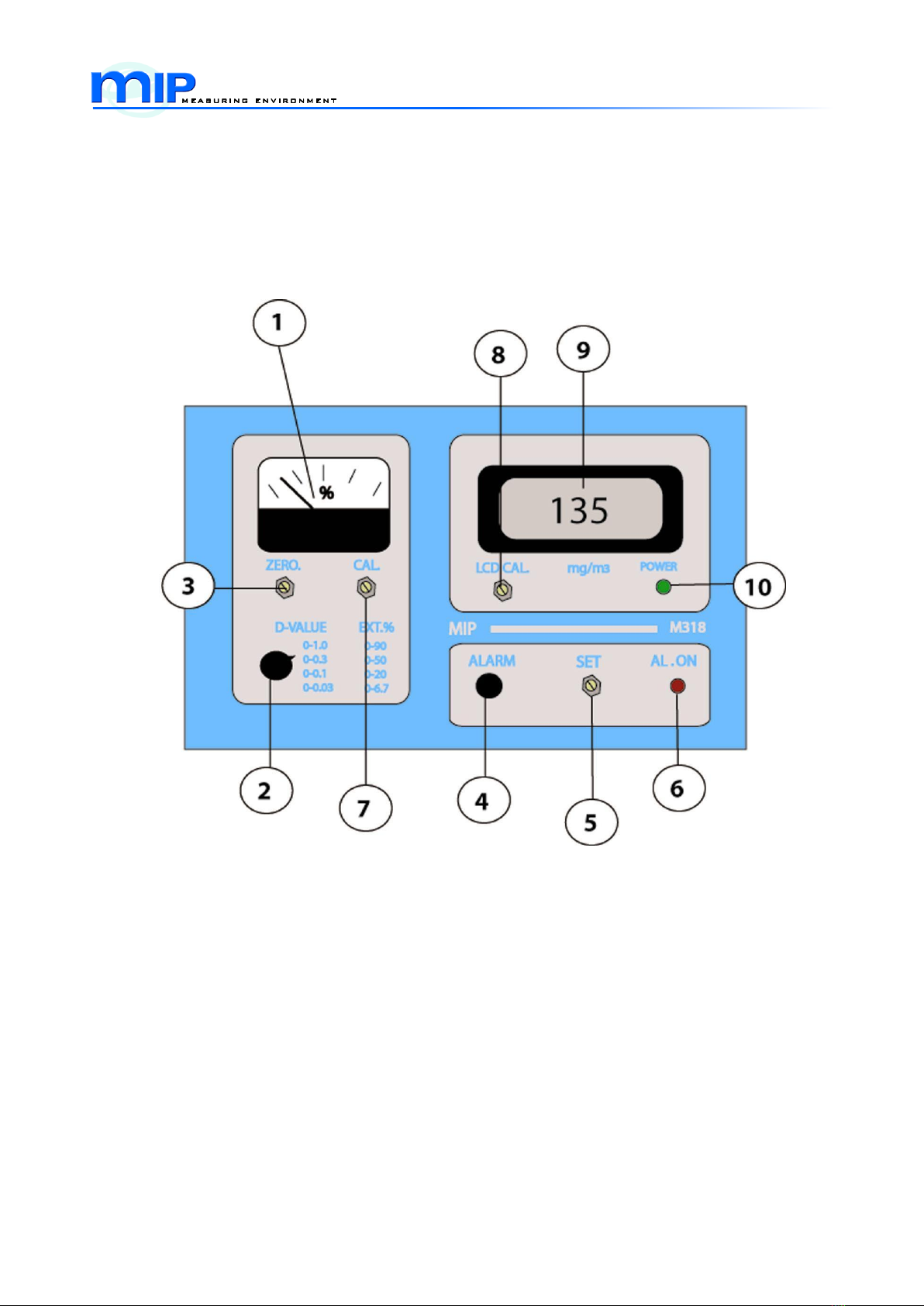
3.1 CONTROLS, DISPLAYS AND SETTINGS ....................................................................10
3.1.1 Indicating meter [1]...............................................................................................10
3.1.2 Range selector [2].................................................................................................10
3.1.3 Zero set screw [3]..................................................................................................11
3.1.4 Alarm test button [4].............................................................................................11
3.1.5 Alarm set screw [5]...............................................................................................11
3.1.6 Alarm indicator lamp [6]......................................................................................11
3.1.7 Calibration screw [7] ............................................................................................11
3.1.8 Mass calibration screw (LCD cal) [8]...............................................................11
3.1.9 Digital LCD-display [9].........................................................................................11
3.1.10 Power indicator lamp [10]...................................................................................11
4. INSTALLATION AND CALIBRATION............................................................................12
4.1. INSTALLATION...............................................................................................................12
4.2 CALIBRATION.................................................................................................................15
4.2.1 Filter set for the dust monitors instructions for the use............................16
4.2.2 Mass calibration....................................................................................................16
4.2.3 Output check..........................................................................................................16
4.3 QUALITY ASSURANCE PROGRAM.............................................................................18
5. SPECIFICATIONS..................................................................................................................19
6. WARRANTY CERTIFICATE.................................................................................................20
7. MANUFACTURER´S CERTIFICATE OF CONFORMANCE TO EC-LABELLING
PROCEDURE..................................................................................................................................22
8. CERTIFICATE OF ORIGIN...................................................................................................23
APPENDIX 1: MONITOR UNIT M 318 MECH. DRAWING.....................................................24
APPENDIX 2: RECEIVER UNIT R318 MECH. DRAWING.....................................................25
APPENDIX 3: RECEIVER UNIT R318 MECH. DRAWING.....................................................26
APPENDIX 4: RECEIVER UNIT R318 MECH. DRAWING.....................................................27
APPENDIX 5: RECEIVER UNIT R318 MECH. DRAWING.....................................................28

Page 3 (41)
APPENDIX 6: TRANSMITTER UNIT L318 MECH. DRAWING .............................................29
APPENDIX 7: TRANSMITTER UNIT L318 MECH. DRAWING .............................................30
APPENDIX 8: TRANSMITTER UNIT L318 MECH. DRAWING .............................................31
APPENDIX 9: LASER UNIT L 318 PCB-LAYOUT...................................................................32
APPENDIX 10: RECEIVER UNIT R 318 PCB-LAYOUT.........................................................33
APPENDIX 11: LM 3188 WIRING ...............................................................................................34
APPENDIX 12: LM 3188 WIRING; UNIVERSAL POWER OPTION.....................................35
APPENDIX 13: INSTALLATION EXAMPLES...........................................................................37
APPENDIX 14 : INSTALLATION.................................................................................................39
APPENDIX 15: MATING FLANGE EXAMPLES.......................................................................40
APPENDIX 16: MATING FLANGE ADAPTERS.......................................................................41

Page 4 (41)
1. INTRODUCTION
1.1 ADVANTAGES AND FEATURES
During the recent years the mass production of different types of lasers has made them eco-
nomically viable products for a broad range of applications, dust monitors among others.
There are two main families of lasers:
Gas lasers, notably Helium-Neon (He-Ne) lasers are available in compact design in-
cluding their hi-voltage power source
Newer Semiconductor lasers today with red, visible beam and with added benefit of
integral power monitoring diode
There are major benefits from using a laser light source whose main features are given be-
low:
Very compact beam. The intense light beam of the laser is typically only a few millimeters
thick. This means that only small holes (10 … 50 mm) are needed in the stack which
simplifies the installation
Good stability and long life. In contrast to designs that use more traditional light bulbs,
which need constant compensation, the laser source is relatively immune to aging ef-
fect. The typical self-life of gas laser is 3 years, and up to 10 years for semiconductor
units. When gas laser fails it is easy to notice as it begins to flicker, much like a fluo-
rescent tube.
Relatively high intensity. Because the laser light power is concentrated at small area, it can
penetrate higher dust densities than conventional light sources.
Operation with known clearly defined wavelength. This makes the theoretical calculations
and their results more predictable as opposed to conventional sources that operate
over broad range of wavelengths and whose spectrum changes with age.
Finally, we would like to mention also our latest light source, the superbright LED that has
many laser-like features. It offers an economic alternative to “real” lasers in some applica-
tions. These superleds are very recent developments and offer the highest recorded output
power of LED-lamps. The radiation happens with very narrow wavelength range, around 640
nm (red) and concentrates on a small cone (4). Our novel stabilizing scheme makes these
superleds fully compatible with semiconductor lasers in the short distance measurements
(<2m).

Page 5 (41)
1.2 DIFFERENT LASER MODELS
There are currently several different laser dust monitors available from MIP.
Gas laser LM 3086, Semiconductor model LM 3188 and Superled model LX 3188.
The basic models are LM 3086 and LM 3188. Both models function with the same principle
measuring directly laser light extinction as optical density. Here is how they differ from each
other:
Model
LM 3086
LM 3188
Technology
Helium-Neon laser
Semiconductor laser
Wavelength
633nm, visible
655 nm, visible
Size ( source )
Weather-proof camera housing
(600*240*170)
Much smaller housing
(145*125*80)
Range
0…0,1 D; 0…0,3 D;
0…1.0 D; 0…3.0 D
0…0,03 D; 0…0,1 D;
0…0,3 D; 0…1,0 D
Beam modulation
None (option: mechanical )
Electronic
Mass density
Optional 0…20g/m3
Digital LCD 0…2g/m3
There are further developments from these basic models available as well. Models with au-
tomatic zero/calibration (LM 3188AZL/AZH, LM 3195 and LM 3086EPA3) or with integral dis-
play unit (LA 3188) are described in their own manuals.
The model LX 3188 is identical in construction with LM 3188-model but utilises the new
superled source (640nm) as described earlier.
The complete laser instrument includes three parts: the source unit, the receiver unit and the
monitor unit. As these are separately available as spare parts, each of these have their own
type marking. The following gives the complete list of units with their differencies from each
other:
1) The laser source units
L 308
Red, He-Ne gas laser
LM 3086
L 318
Red, Electr.mod. semiconductor laser
LM 3188
L 318AZL/AZH
Red, Chopped semiconductor laser
LM 3188AZL/AZH
X 318
Red, Electr.mod. superled source
LX 3188
2) The receiver units
R 308
No additional electronics included.
LM 3086
R 318 (LM)
De-modulation electronic included.
LM 3188
R 318AZL/AZH
Sync.detection electronic included.
LM 3188AZL/AZH
R 318 (LX)
De-modulation electronic included.
LX 3188
All models have optically matched semiconductor detector with 50mm glass lens.

Page 6 (41)
3) The monitor units
M 308
Range 0…3 D
LM 3086
M 318
Range 0…1 D; LCD display 0…2g/m3
LX 3188 / LM 3188
M 318AZL
Range 0…1 D; LCD display 0…2g/m3
LM 3188AZL
M 318AZH
Range 0…3 D; LCD display 0…20g/m3
LM 3188AZH
All monitor units have analogue meter 0 … 100 % of the selected D-value scale, voltage and
current outputs as well as alarm relay. Also controls for zero, span and mass calibration (M
318) are included as well as relay limit settings.
There are some options available for larger area detectors or modified operation ranges for
basic unit. Consult factory on these options.
1.3 APPLICATIONS FOR DIFFERENT LASER MODELS
The different laser types, obviously, address different applications. As a guideline following
information is based on practical installations:
LM 3086 Red, gas laser works best in relatively high-dust environment (>100mg/m3). It
has become a sort of standard in pulp mill applications, recovery boiler, lime
kilns, etc.
LM 3188 Semiconductor laser is used in relatively low-dust environment (< 1g/m3) or
where the space is limited.
LX 3188 Superled model can be used instead of LM 3188 where the measuring length
is short enough (<2m) or where the price is of primary importance.
2. THEORY OF OPERATION
When a monochromatic light beam, such as laser beam, traverses through gas that contains
particulate matter, the intensity of the beam will decrease by absorption and scattering pro-
cesses within the particle distribution. The net effect can be described by so called Lambert-
Beer law as (eq.1):
Where I0is the source intensity of laser light
I is the measured intensity at the detector
x is the length of the beam passage in particle distribution
is a constant that depends on particle diameter, laser
wavelength and any absorption process present
)*(
0x
eII

Page 7 (41)
2.1 OPACITY DEFINITION
Opacity is defined as the property of the stack gases to attenuate visible light due to the pres-
ence of particulate in the effluent. The amount of the attenuation depends on the concentra-
tion of the light absorbing or scattering particulate and on the length of the measuring path.
The basic definition of opacity requires that an instrument measures light intensity at the
source (Io) and light intensity at the receiver (I) after it has passed the stack effluent. The
opacity is expressed as a percent figure Op% (eq.2):
A fully transparent (clear) stack gas has the opacity of 0% and a
fully opaque gas has the opacity of 100%.
2.2 D-VALUE DEFINITION
Another concept, useful in this connection, is the optical density, D. The D-value is defined as
(eq.3):
Where I and I0are defined as earlier. It is to be noted that D-value is of general nature and
does not depend on measurement length or particle properties.
To account for many different applications and measurement set-ups the D-value as solved
from the eq. (3), is the basic quantity for the MIP-monitors. Thus the indicator range is scaled
in D-values and optical filters with known D-values are readily available to check the proper
operation of the instrument.
2.3 MASS-VALUE DEFINITION
The user is, however, normally more interested in dust or particulate concentration in terms
of mass concentration (mg/m3) than D-values. The main problem for given measurement set-
up is then to express the measured D-value, as mass concentration. Most reliable method to
do this is calibration by simultaneous gravimetric sampling and D-value measuring in differ-
ent particulate concentrations that are likely to appear in practice. Once the relation between
mg/m3- and D-values is established the problem is solved.
It is also possible to further develop theoretically the equations (1) and (3) together with sim-
ple model of particle distribution. The achieved results agree surprisingly to many real,
measured dust concentrations and gives valuable information for applicability of laser dust
measurement.
This model assumes the distribution consisting of identical particles with diameter of d and
density (mass/volume) of . Now, combining equations (1) and (3), there is a relation
between D-value and mass concentration (eq.4):
100*1%
0
II
OP
D
II
10*
0

Page 8 (41)
Where d = particle diameter micrometers
= particle density grams/cm3
L = measurement length in dust meters
D = measured D-value optical density
M = mass concentration of dust grams/m3
This “mass formula” is valid for particle sizes from 0,7 m upwards.
LDd
M***8,0

Page 9 (41)
3. INTRODUCTION OF LASER DUST MONITOR LM 3188
Figure 1.
LM 3188 is unity, which includes transmitter, receiver and monitor. (Figure 1.) Opacity moni-
tor’s optimal use is for stack up to 20 meters. There are no moving parts, so it has minimal
maintenance. It has large operation range (0 … 90 %). Its optic need is minimum so there is
less maintenance. LM 3188 has good stability and reliability. LM 3188 has both analogue and
digital display in monitor unit. There are 4 operator selectable measuring ranges. Most of
controls and displays are included in monitor unit.
Typical applications for LM 3188 are power plants, cement factories and tunnels.
LM 3188 has excellent beam collimation (0,04 °), so user don’t need to use lenses or mirrors
in the transmitter. This makes the system reliable and simple. The alignment of the beam is
easy because the beam is narrow. Standard wavelength guarantees long-term accuracy and
stability. Analyser can be transferred to another location without factory calibration.

Page 10 (41)
3.1 CONTROLS, DISPLAYS AND SETTINGS
The faceplate of the M 318 monitor unit is pictured which is below. Controls displays and
settings are indicated by numbers
3.1.1 Indicating meter [1]
Indicating meter, which displays the %-value in selected D-range. If, for instance, the reading
is 40 % and the selected D-range is 0…0,3 D, then the measured D-value is
0,3 D 0,4 = 0,12 D.
The indication follows continuously the variation in dust concentration.
3.1.2 Range selector [2]
Range selector, which enables the user to select a proper monitoring range for various appli-
cations. Four ranges: 0 …0,03 D;0 … 0.1; 0 … 0.03 and 0… 1,0 D in D-values are available
for M 318. Ranges can be extending up to 0 … 3.0 D. The corresponding extinction (opacity)
%-values are given along the D-value ranges.

Page 11 (41)
3.1.3 Zero set screw [3]
This is very important adjustment, which allows after installation to set zero (D-value) level.
The zeroing should happen in as dustless condition as possible. When measuring path is
clear of any interfering particles, the zero screw is turned until the meter (and display) indi-
cates 0-reading.
3.1.4 Alarm test button [4]
By pressing this button, the monitor shows the set alarm level, which activates the alarm re-
lay. Note, that the level might be over the current selected range and the range selector must
be used to find the set level.
3.1.5 Alarm set screw [5]
By activating the alarm test button, and using this screw, the alarm level can be re-adjusted.
3.1.6 Alarm indicator lamp [6]
The alarm indicator lamp lits when the alarm level is exceeded.
3.1.7 Calibration screw [7]
Used after zero level is set to adjust the reading to correspond a known D-value calibration fil-
ter. This is normally done in the factory and user should have no need for re-adjustment. This
is the main optical calibration adjustment for the monitor.
3.1.8 Mass calibration screw (LCD cal) [8]
This screw is intended for setting up the relation between the D-value and the digital mass
reading. The relation can be verified with gravimetric sampling or calculated from mass formu-
la. The factory setting is based on assumption, that D-value of 1,0D corresponds to 800
mg/m3.
3.1.9 Digital LCD-display [9]
This display shows mg/m3–reading of the dust concentration and is independent from the set-
ting of D-value range.
3.1.10 Power indicator lamp [10]
This LED-lamp is lit, whenever the monitor is powered.

Page 12 (41)
4. INSTALLATION AND CALIBRATION
4.1. INSTALLATION
It is clear, that the installation environment is different in each application. That is why we pro-
vide only a minimum of installation hardware with the instrument. The gas laser has a specific
installation foot and semiconductor lasers as well as all receivers, come with the flanges that
have elliptic holes for adjustment.
1:Use 5mm hex key and 8mm wrench to adjust angle and position of the trans-
mitter unit with G 1/2 puge air thread.
2: Use 10mm wrench and 8mm wrench to adjust angle and position of the transmitter unit with M5 purge air
thread.

Page 13 (41)
3: Use 10mm wrench to adjust position of the reveiver unit. (Version with upgraded purge air flow pictured).
Main alignment adjustment should be done from transmitters installationg flange as shown
on pictures 1 and 2.
As the laser beam is very compact, only small holes (10…50 mm dia) to get beam through,
are needed. Normally there is a small under pressure inside the stack, and outside air auto-
matically keeps the holes clean. In case there is overpressure in the stack, but source and re-
ceiver can be flange-mounted. Then, using the instrument-air purge system to slightly over-
come stack pressure keeps the instrument clean and functional.
The mounting system obviously varies from case to case. Basically there are three different
mounting systems:
a) Mounting in the stack itself by L-type supports
b) Mounting on the support structures (or on the floor/roof) around the stack. In this case
possible temperature related movement of the stack may require elliptical holes in the
stack.
c) Mounting on the flanges welded in the stack. This case provides a solution, when
there is overpressure in the stack and gas escape from small holes is not allowed.
A specific problem appears when the dust content is very high. Then you might need to short-
en the laser path by horizontal tube inside the stack. As a rule of thumb, 1 m distance is
enough for concentrations 1-5 g/m3. Higher concentrations need shorter path.

Page 14 (41)
There are other environmental factors that can influence the measurement. Here is a check
list of the factors that can cause trouble for measuring dust content:
1 Trying to measure too small concentrations
2 Using too long distance for very high concentrations
3 Orientation and vibration problems when using long measuring distances
4 Interfering other substances, than the measured dust
5 Other light sources (sun, lighting) affecting the receiver
6 Dust or dew accumulating to optical surfaces of the laser or receiver
Factors 1 and 2 relates to measuring angle and inherent intensity fluctuation in both LM 3086
and LM 3188, as discussed in connection with mass density estimation. The mass formula
can be used to estimate the mass concentration range, based on particle properties and path
length.

Page 15 (41)
Factor 3 refers to allowed beam direction changes that can point the beam outside the detec-
tor. The beam profile differs in He-Ne and semiconductor lasers. In the He-Ne laser, the criti-
cal distance, where beam diameter exceeds the receiver active area, is around 13…18 m. For
the semiconductor model this is 25…35m. For critical cases, larger area detectors are availa-
ble. Consult the factory.
Factor 4. The selected wavelength of the laser is such, that most common 3-atomic gases
SO2, CO2, H2O, will not affect the measurements. However, when water exists as liquid
droplets or fog, it will be “seen” by the laser as particles. Applications of this kind, such as in-
volving wet scrubbers, should be checked carefully for this kind of trouble.
Factor 5. Sun or other artificial light sources, can add to the laser light and thus falsify the re-
sults. For modulated laser beam this is not a problem, as the receiver is tuned to modulation
frequency. For unmodulated beam (LM 3086) the receiver should be shielded from external
light.
Factor 6.This is a major problem in competing units, but not normally in laser installations, that
are installed remote to stack. Both laser and receiver should be provided with dry, clean in-
strument air to keep slight overpressure inside the units.
4.2 CALIBRATION
With calibration we mean here a broader range of operations including zero set, optical cali-
bration with filters, mass calibration and checking the outputs of the instrument.
Actually zero setting and optical calibration can as well be performed at the laboratory work-
bench, using the same distance as in actual measurement situation.
Set instrument zero as follows:
First, after switching the laser and measuring unit on, wait for 2 hours to let the laser
output power to stabilize
Then, using the most sensitive measuring range, set the meter to zero by zero ad-
just screw at the front plate. Note: Be sure, that while making the zero adjustment, the
channel is free from dust, ie. this adjustment corresponds to physical zero dust state.
Calibration means optical calibration for D-value and possibly mass calibration.
Optical calibration is performed as follows:
Calibration check can be made any time by optical neutral density filters. For in-
stance, by interposing D = 0,3 value filter in the laser beam, while the meter is set for
0 …1,0 D range, the meter should display 30 % more than without the filter. If neces-
sary, the sensitivity can be altered by “cal” adjustment.
The filter set OF 308 offers the possibility for both calibration and linearity checks of the in-
strument. Optical calibration is eased by the fact, that filters and instrument scale show the
same quantity, enabling calibration check, even while the instrument is in operation. Also a
field calibration kit FK 308 containing only one filters, is available.

Page 16 (41)
4.2.1 Filter set for the dust monitors instructions for the use
The dust monitor LM 3188 should be warmed-up and showing a steady D (zero if the meas-
urement path is clear of the dust) before calibration with the filters.
Insert the filter in the laser beam at right angle (90) beam hitting the center of the filter. The
best place for the filter is flush with the receiver R 318 surface. If this is no possible, then as
near the receiver as possible.
The indication of the LM 3188 should now increase to D+X, where X is the filter’s D-value giv-
en in associated filter graphs, at the wavelength 655 nm. Use the filter consistent with the
measurement range, ie. Filter that gives clear deflection at the indication, but does not require
range switching.
If the increase in the indication differs from he known X-value, the LM 3188 “CAL”-screw can
be used to set the calibration right. When the filter is removed, the indicator should return to
previous base-value D.
The linearity of the instrument at other ranges can be checked similarly with different filters of
the set.
4.2.2 Mass calibration
Mass calibration can happen based on theoretical calculation or on actual sampling proce-
dure.
Theoretical mass calibration is based on the formula 3between the optical density and mass
density of the dust. Then, it is supposed that the average size (diameter) and particle gravity
is known reasonably well.
For mass calibration select a known D-value filter (say D = 1,0) and calculate the mass equiv-
alent with formula. Interpose the filter in the beam and adjust “LCD.CAL”-screw, until digital
display indicates the calculated value.
Mass concentration with sampling is the preferred method, when there is no knowledge of
particle properties or when best of accuracy is demanded. By taking the samples in various
concentrations, and at the same time recording the measured D-values, the relation between
mass and optical density can be established. Theoretically this would be straight line.
4.2.3 Output check
There are two kinds of outputs. Voltage output (0 …1V) and current output (4 … 20 mA).
Both of these are available from instrument terminal block as are the alarm relay contacts.
The outputs are directly proportional to analogue meter %-indication. This means, that the
same D-value can give you different outputs, depending on the selected range.
Take, for example, D = 0,5 filter and select range 0 … 1,0 D. Now, the meter should indicate
50 % and corresponding voltage output will be 50 % of 1 V or 500 mV and current output
should be 4 mA + (50 % (20 - 4)mA) = 4mA + (0,5 16 mA) = 12 mA.

Page 17 (41)
Next, use the same filter and the range 0…3,0 D and the result should now be:
%-indication = 0,5 / 3,0 = 17 %
Voltage output= 17 % 1 V = 170 mV
Current output = 4mA + (17 % (20 - 4)mA) = 6,7 mA
Note, that “zero” and “cal” adjustments will affect the outputs, but
“LCD-CAL” will not.
Note. If you are using both outputs at the same time, you must use a galvanic isolation
in the current output. Voltage output and terminal is at 0V potential, while current
output (-)-terminal is at (-15V)-potential.

Page 18 (41)
4.3 QUALITY ASSURANCE PROGRAM
In the factory, we are keeping the track with each instrument delivered and maintain for
service purposes individual test cards for each manufactured product. Actually the QAP
goes further than that. It records all the people that are involved in the manufacturing pro-
cedure, their qualifications and duties. It also identifies all the laboratory instruments, used
during the testing of the products, specifies what is documented and how these documents
are filed. An empty, individual test sheet is enclosed. It shows what features are tested in
the laser monitors. As we normally do not know what kind of dust will be measured by the
user, we assume the “standard” particles of 1 micrometers and 1 kg/dm3. Then we perform
mass calibration, based on to these values and assumed measuring path of 1 m. That is
why the “normalized” laser meter will give a reading of 800 mg/m3with a filter =1.0D, when
it leaves the factory. All other points are carefully tested at our laboratory and the meters
carefully adjusted for the best linearity with a calibrated filter set.

Page 19 (41)
5. SPECIFICATIONS
Laser Unit L 318
Laser type
Semiconductor laser class II
Optical Power
1,2mW nominal
Wavelength
655nm, visible light
Power stability
1%, warm-up 5 minutes
Power supply
15V, from monitor unit
Operating temperature
-20C to +60C (-4F to 140F)
Receiver unit R 318
Detection
Optically matched semiconductor detector with
50mm glass lens.
Power supply
15V, from monitor unit
Operating temperature
-20C to +80C (-4F to 175F)
Monitor Unit M 318
Analog display
0…100% linear scale (D-value)
Digital display
0…2000 mg/m3
Outputs
Voltage 0…1V, 50
Current 4,0…20,0mA, 500max.
Relay 220 VAC, 1A max.
Power supply
230VAC 14VA
115VAC 14VA (optional)
Operating temperature
0C to +70C (32F to 158F)
Ranges
Switch position
D-value
Opacity %
Mass value
1
0…0,03D
0… 6,7 %
0 … 24 mg/m3
2
0…0,1D
0… 20 %
0 … 80 mg/m3
3
0…0,3D
0… 50 %
0 … 240 mg/m3
4
0…1,0D
0… 90 %
0 … 800 mg/m3
* Factory settings
The range values are for particle size 1 micrometer, measuring distance 1 m.
For other type of particles and measuring length, range values varies.

Page 20 (41)
6. WARRANTY CERTIFICATE
BRAND: MIP
TYPE: LM 3188
SERIAL NUMBERS
MONITOR: _________________________
TRANSMITTER: _________________________
RECEIVER: _________________________
MIP Laser Dust Monitors are warranted to be free from defects in materials and workmanship
for a period of 12 months from the date of the initial shipment. This warranty does not extend
to damage caused by negligent or improper handling in use, storage, or transportation, nor for
products from which the original identification markings or labels have been removed, de-
faced, or altered.
Special contracts or contracts for non-standard products may have modified terms of warranty
and, in such cases, the terms as stated in the individual contract must be signed by the duly
authorized officer of MIP and will supersede the standard terms. MIP reserves the right to
change our warranty policy without any prior notice. Please contact MIP directly with any
questions pertaining to your warranty.
MIP will make the final determination as to the cause or existence of the defect and, at our
discretion, repair or replace the products that prove to be defective during the warranty period.
Products replaced under warranty will be warranted only for the balance of the warranty peri-
od of the originally supplied equipment. Additionally, any purchased replacement parts, i.e. la-
ser tubes, power supply modules, etc., are warranted for a six-month (6) period.
This warranty extends only to the original purchaser of the equipment from MIP, and is not
transferable. The purchaser must notify MIP within 15 days of first noticing the defect and
promptly return the defective product before the expiration of the warranty period. Products re-
turned from persons not employed by the original purchaser will not be evaluated without prior
consent from the original buyer.
Products believed by the purchaser to be defective shall be returned to MIP. Transportation,
insurance, duties, etc., are to be paid by the purchaser. Repaired or replaced products will be
returned to the purchaser by MIP, F.O.B. city of destination, domestic as well as foreign terri-
tories. MIP will not be responsible for any duties, levies, taxes, etc., on returned items.
Warranty limitations for light sources:
This warranty does not apply to laser diode, laser tube and led light source failures due to the
electrostatic damage, excessive voltage or current, or operation at the temperatures beyond
recommended levels.
Table of contents