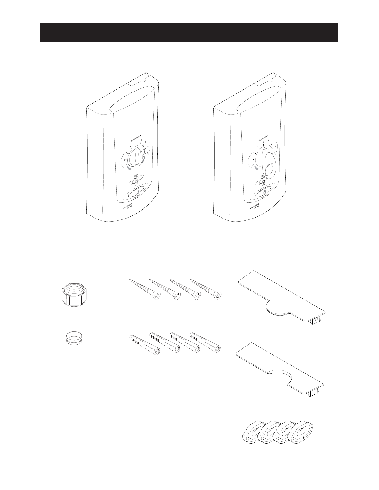
Mira Advance Low Pressure Standard User manual

1
Installation Guide
MIRA ADVANCE ATLP
LOW PRESSURE
9.0 kW
PUMPED ELECTRIC
SHOWER
ADJUSTABLE TEMPERATURE LIMIT THERMOSTATIC
This product is suitable for gravity cold water only.
Please leave these instructions at the installation address.

2
If you experience any difculty with the installation or operation of your new Pumped
Electric Shower, then please refer to 'Fault Diagnosis', before contacting Mira
Showers. Our contact details can be found on the back cover of this guide.
CONTENTS
Shower Models ........................................................................................ 3
Guarantee ............................................................................................3
Patents and Design Registration..........................................................3
Important Safety Information .................................................................4
Pack Contents ......................................................................................... 6
Specications ..........................................................................................7
Standards and Approvals .....................................................................7
Dimensions...........................................................................................8
Installation Requirements ...................................................................... 9
General................................................................................................. 9
1. Plumbing .......................................................................................... 9
Pipework .................................................................................... 11
Plumbing Schematic Diagram.................................................... 11
2. Electrical.........................................................................................12
Electrical Schematic Diagram .................................................... 12
Installation .............................................................................................14
Commissioning .....................................................................................18
Set Maximum Temperature and Commissioning Cycle......................18
BEAB Care......................................................................................... 19
Maintenance...........................................................................................20
Fault Diagnosis......................................................................................20
1. Installer Troubleshooting Guide......................................................20
2. Diagnostic Procedure..................................................................... 21
Error Code Table ................................................................................22
BEAB Care In-Service Tests.................................................................25
Spare Parts ............................................................................................ 28
Wiring Diagram...................................................................................... 30
Accessories ...........................................................................................31
Customer Service..................................................................................32

3
SHOWER MODELS
Mira Advance Low Pressure models covered by this guide
Product
Variant
Adjustable
Temperature
Limit
Extended
Lever
Control
Model
No.
Standard
9.0 kW J97I
Flex
9.0 kW J97K
Guarantee
For domestic installations, Mira Showers guarantee the Mira Advance ATLP against
any defect in materials or workmanship for a period of two years from the date of
purchase (shower ttings for one year).
For non-domestic installations, Mira Showers guarantee the Mira Advance ATLP
against any defect in materials or workmanship for a period of one year from the
date of purchase.
For Terms and Conditions refer to the back cover of this guide.
Recommended Usage
Domestic
Light Commercial
Heavy Commercial
Healthcare
Patents and Design Registration
Design Registration: 000738141: 0003, 0006, 0007, 0009
Patents: GB: 2269466, 2270370, 2298478, 2298479, 2298481,
2289323, 2359339.
Ireland: 80655, 83692.

4
Installation must be carried out in accordance with these instructions, and must be
conducted by designated, qualied and competent personnel.
WARNING!
Follow all warnings, cautions and instructions contained in this guide, and on or
inside the shower.
1. This shower can deliver scalding temperatures if not operated, installed
or maintained in accordance with the instructions, warnings and cautions
contained in this guide and on or inside the appliance.
2. Products manufactured by us are safe and risk-free, provided that they are
installed, used and maintained in good working order, in accordance with our
instructions and recommendations.
3. This product is suitable for installation within Zone 1 and is rated IPX4.
4. Isolate the electrical and water supplies before commencing installation. The
electricity must be turned off at the mains and the appropriate circuit fuse
removed, if applicable.
5. Mains connections are exposed when the cover is removed.
6. Refer to the wiring diagram before making any electrical connections.
7. Make sure all electrical connections are tight, to prevent overheating.
8. Make sure that any pipework that could become frozen is properly insulated. The
shower unit must not be tted where it may be exposed to freezing conditions.
9. The water supplies to this product must be isolated if the product is not to be
used for a long period of time. If the product or pipework is at risk of freezing
during this period they should also be drained of water.
10. DO NOT operate this appliance if it is frozen. Isolate the electrical supply and
allow to thaw. Check for leaks before reconnecting the electrical supply.
11. DO NOT install the product in a position in which service access is restricted.
12 If the shower is dismantled during installation or servicing then upon completion
the product must be inspected to ensure there are no leaks.
13. DO NOT t any form of outlet ow control (e.g. trigger handsets) as the outlet
acts as a vent for the tank body. Only Mira recommended outlet ttings should
be used.
14. This product is not suitable for areas with high humidity (i.e. steam rooms).
15. THIS APPLIANCE MUST BE EARTHED. MAKE SURE SUPPLEMENTARY
BONDING COMPLIES WITH THE ‘REQUIREMENTS FOR ELECTRICAL
INSTALLATIONS’ BS7671. This pumped electric shower is intended to be
permanently connected to the xed electrical wiring of the mains system.
16. This appliance must be provided with means for disconnection that is
incorporated into the xed wiring in accordance with the relevant local wiring
regulations.
17. This appliance is suitable for installation within the shower area. It must be
IMPORTANT SAFETY INFORMATION

5
positioned over a water catchment area with the controls at a convenient height
for the user. The shower tting should be positioned so that it discharges down
the centre line of the bath, or across the opening of a shower cubicle, and must
be directed away from the appliance.
CAUTION!
1. Read all of these instructions and retain this guide for later use.
2. The electrical installation must comply to 'BS 7671 (commonly referred to as the
IEE Wiring Regulations) and all relevant building regulations, or any particular
regulation or practice specied by the local electricity supply company.
3. The plumbing installation must comply with all national or local water regulations
and all relevant building regulations, or any particular regulation or practice
specied by the local water company or water undertakers.
4. Switch off the appliance at the electrical isolating switch when not in use. This
is for safety and is recommended with all electrical appliances.
5. This appliance is not suitable for use with any form of electronic timer. The
shower must be shut down in accordance with the instructions contained in
this installation guide, or the separate user guide.
6. Having completed the installation, make sure that the user is familiar with the
operation of the appliance.
7. When this appliance has reached the end of its serviceable life, it should
be disposed of in a safe manner, in accordance with current local authority
recycling, or waste disposal policy.
8. Please pass this guide on in the event of a change of ownership of the installation
site.

6
PACK CONTENTS
Tick the appropriate boxes to familiarise yourself with the part names and to conrm
that the parts are included.
Documentation
1 x User Guide
1 x Installation Template
1 x Guarantee Registration Document
1 x BEAB Care In-Service Test Record
1 x Mira Advance Low
Pressure Standard
1 x Compression Nut 4 x Wall Screws
1 x Cover Insert
(blank)
4 x Wall Plugs
1 x Cover Insert
(pipe)
4 x Rubber Feet
1 x Olive
Or
1 x Mira Advance Low
Pressure Flex

7
SPECIFICATIONS
Plumbing Supply
Supply Source Gravity fed or pumped cold water only.
Maximum Static Pressure 100 kPa (1 bar)
Minimum Static Pressure 0.8 kPa (0.008 bar) (10 kPa BEAB Care)
Maximum Inlet Temperature 30°C (20°C BEAB Care)
Minimum Inlet Temperature 2°C (5°C BEAB Care)
Inlet Connection ½" BSP male & 15 mm compression
tting.
Outlet Connection ½" BSP male fitting
Electrical Supply
Nominal Rating at 230 V 8.3 kW
Nominal Rating at 240 V 9.0 kW
Supply Fuse/Circuit Breaker 40 Amps
Residual Current Device RCD 30 mA
Supply Cable
No larger than 16 mm²
Note: Refer to current IEE regulations
and BS 7671 to determine minimum
cable size.
Isolation Switch 45 Amp Double pole, with 3 mm contact
separation.
Maximum Ambient Temperature 30°C
Minimum Ambient Temperature 2°C
Duty Cycle 30 minutes on / 30 minutes off.
Standards and Approvals
The Mira Advance ATLP complies with the requirements of the BEAB Care Mark
Standard and the relevant directives for CE marking.
The BEAB Care mark is invalid if the product is not installed and used in accordance
with the manufacturer's specications and instructions.

8
Dimensions
Advance Low Pressure
Standard
Advance
Low Pressure Flex
402 mm
243 mm
100 mm 115 mm
84 mm 84 mm

9
General
We recommend that the product be brought into the room where it is to be installed
and left to acclimatise to room temperature, this will reduce the possiblilty of
condensation on electronic components. This product works best when supply
temperatures and pressures remain stable and within the product specications, refer
to section 'Specications'. If the supply conditions fall outside the specications,
the shower may go into a safe shut down condition.
If pipework and/or electrical cables enter the shower from the rear through a hole in
the wall, provision must be made to prevent water ingress back into the wall structure.
1. Plumbing
Refer to section: 'Important Safety Information' rst.
1.1 The shower is designed to operate with gravity fed water supplies providing
pressures from 0.8 kPa * (0.008 bar / 80 millimetres head) to 100 kPa (1 bar
/ 10 metres head) (i.e. the vertical distance from the base of the cold cistern
to the top of the main unit of the shower). The unit should be never be tted
to a mains supply or where the above maximum pressure may be exceeded.
Failure to comply with this may result in product damage leading to signicant
uncontrolled leakage from the unit.
* Note: In practice the minimum head required will increase with pipe length
and the guide given in the section 'Pipework' should be used to make sure
that adequate head is available for any given installation.
The shower MUST have its own separate supply from the cistern.
INSTALLATION REQUIREMENTS
Incorrect Cistern Take Off
Debris from the bottom of
the cistern and air generated
when the cistern rells will
enter the shower supply.
Correct Cistern Take Off
Positioned away from the ball
valve, with a 25 mm distance
up from the base of the cistern.
This connection will prevent air
and debris entering the shower
supply.
25 mm
25 Gallon/113 Litre Cistern

10
1.2 Do not use sealing compounds on any pipe ttings or joints.
1.3 To avoid damage to the case when soldered ttings are used, pre-solder the
pipework and ttings before connecting them to the inlet connector assembly.
1.4 Avoid layouts where the shower hose will be sharply kinked. This may reduce
the life of the hose.
1.5 Supply pipework MUST be ushed to clear debris BEFORE connecting the
appliance. Debris will reduce the performance of the shower.
Avoid running the pipework through excessively hot or cold areas such as hot
loft spaces, airing cupboards, or in close proximity to hot water pipes. If this
cannot be avoided, we would recommend insulating the pipes.
1.6 The shower must be tted onto a tiled or sealed nished surface, i.e. on top of
the tiles. DO NOT tile up to the sides of the shower or use a sealant around the
case. Failure to do this may cause appliance failure. To ensure the case and
other components are not put under strain during installation always provide
mechanical support when making plumbing connections. Upon completion of
the installation ensure connections and back case are not under any stress
due to misaligned pipework or electrical cables.
1.7 We recommend that a non-restrictive (free owing) isolating valve is tted in
the cold water supply pipe from the cistern to the shower, to allow maintenance
of the shower.
1.8 When installed in very hard water areas (above 200 ppm temporary hardness)
your installer may advise the installation of a water treatment device, to reduce
the effects of limescale formation. Any malfunction due to limescale is not
covered by the manufacturer's guarantee. Your local water company will be
able to advise the hardness of water in your area.
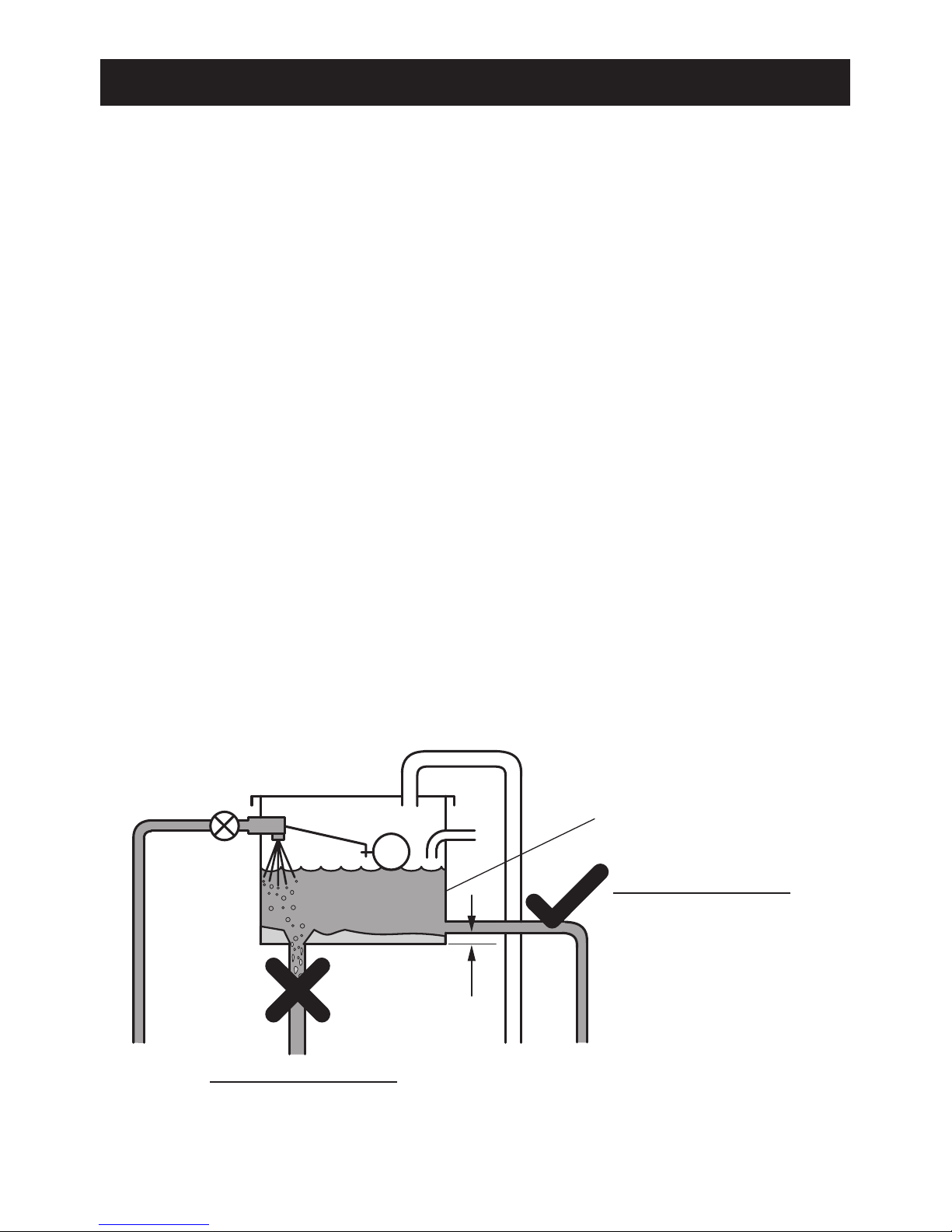
1.9 To prevent the possibility of backsiphonage, the handset must be prevented
from reaching within 25 mm of the spillover level of any bath, shower tray or
washbasin. The supplied hose retaining ring should enable this to be achieved
for the majority of shower installations. However, there will be occasions when
the hose retaining ring will not provide a suitable solution. In these instances,
a double checkvalve must be tted to the outlet. Double checkvalves tted in
the shower's inlet supply can cause a pressure build-up, which could exceed
the maximum static inlet pressure for the appliance. The handset must be
prevented from reaching within 30 mm of the spillover level of any WC, bidet
or other basin that is classied higher than uid category 3.
1.10 Rear entry plumbing is accommodated without the need to recess the 15 mm
inlet compression connector. If pipework and/or electrical cables enter the
shower from the rear through a hole in the wall provision must be made to
prevent water ingress back into the wall structure.
1.11 The shower is tted with a pump motor, and some mechanical noise can be
expected in addition to the noise generated by the spray from the handset. The
type of wall surface will affect the perceived sound levels. Stud partition and
panel walls have a tendency to resonate, whilst solid walls provide the quietest

11
operation. The tone of the pump motor may change when the temperature
control knob is adjusted. This is quite normal.
1.12 Use a minimum of 15 mm diameter supply pipework. It should be noted,
however, that on long pipe runs this should be increased to 22 mm (refer to
section 'Pipework' for guidance). When using exible plastic pipe it is essential
that the pipe is kept at and not looped up at any point as this may lead to air
build up.
1.13 Long pipe runs and excessive use of 90° elbows will signicantly reduce the
available head to supply the shower. The pipework table should be completed
to ensure that adequate head is available for any given application.
Pipework
The dimension (x) is calculated from the table below to give you a minimum effective
head of 80 mm which is necessary to produce a satisfactory shower in all conditions.
Example! The example below is based on the diagram above with 15 mm pipework,
A = 1.5 m, B = 0.75 m.
Plumbing Schematic Diagram
A
B
X
Size Quantity Head Loss
(mm)
15 mm Pipe (A) 1.5 + (B) 0.75 = 2.25 x 120 270
22 mm Pipe (A) + (B) = x 20
15 mm Elbow Number or Elbows 1 x 55 55
22 mm Elbow Number or Elbows x 15
Minimum Effective Head 80
(x) mm 405
Free owing
isolator valve

12
2. Electrical
Refer to section: 'Important Safety Information' rst.
2.1 In a domestic installation, the rating of the electricity supplier’s fuse and the
consumer unit must be adequate for the additional demand. All Mira Advance
ATLP pumped electric showers are high power appliances, so it is essential to
contact the electrical supply company to make sure that the supply is adequate
for the appliance. Voltage drop due to local heavy demand will reduce the
shower’s performance.
2.2 The appliance must be earthed by connecting the supply-cable earth conductor
to the earth terminal.
Any supplementary bonding and supply cable size must conform to BS 7671.
2.3 As a guide only, and in accordance with BS 7671 we recommend close circuit
protection:
i.e. 9.0 kW = 40 Amp
In accordance with BS 7671,a 30 mA Residual Current Device (RCD) MUST
be included in the electrical circuit. This may be part of the consumer unit or a
separate unit.
A separate, permanently connected supply must taken from the consumer
unit to the appliance through a double-pole switch, which has at least 3 mm
contact separation. The switch can be a ceiling mounted pullcord type or a wall
mounted switch in the applicable zone area.
2.4 DO NOT exert strain on the terminal block. Make sure that the electrical
connections are tightly screwed down.
2.5 Unless otherwise stated, electrical equipment such as extractor fans, pumps
must not be connected via this product.
Electrical Schematic Diagram
Optional Outlet
Double Checkvalve
45 Amp Double-pole
Isolating Switch
Gravity Fed or Pumped
Cold Water Supply
Consumer Unit
Free owing
Isolating Valve
Supply cable

13
Terminal
Block
Internal
Pump
Tank Assembly
Outlet
Connector
Flow Valve
Turbine and
Inlet Sensor
Wire 75
Earth
Inlet Clamp
Relay Board
Thermal Switch
Element
Assembly
Clip (secures
thermal switch)
Outlet
Sensor
Ribbon Cable
(connect to
front Cover).
Flow Valve
Air Bleed
Button
Mira Advance Low Pressure

14
INSTALLATION
Refer to section: 'Important Safety Information' rst.
This installation covers all models of the Mira Advance ATLP Thermostatic
shower.
1. Electrical supply
is turned off at the
mains.
2. Determine the shower
position, leaving
adequate space for
maintenance.
3. Remove cover screws.
4. Remove front cover.
Determine supply pipe
position.
5. Turn inlet connector to
suit supply pipe.
Do not trap green
(earth) wires.
6. Complete any
soldering required
away from appliance.
8. Caution! Do not drill
into buried cables or
pipes.
7. Flush a minimum of
10 litres (2 gallons)
through pipework prior
to connection.
10 mm
200 mm
9. Use template provided
to mark and drill
required xing holes.
Screws and plugs are
supplied for 4 holes.
Mira Advance ATL Low Pressure
Attention Installer
IMPORTANT!The following key details should be read in
conjunction with the Installation and User Guides.
Required
Fixing Hole
Required
Fixing Hole
1173258-W7-A ©Kohler Mira Limited, June 2011
For technical support and general enquires,
spare parts and after sales service contact us on:
Telephone: 0870 241 0888
Fax : 01242 282 595
Required
Fixing Hole
(if using 4 screws)
Required
Fixing Hole
(if using 4 screws)
Do not install the appliance where it
may become frozen.
Do not drill into buried cables or
pipes.
Avoid dust contamination of the
product by using this template to mark
and drill into the wall. Drill appliance
case separately.
Do not use alternative screws to
secure the cover.
Do not seal any part of the appliance.
Use the correct supply cable
size. Refer to BS 7671.
Required
Fixing Hole
(if using 3 screws)
pipework before connecting
to the appliance.
Determinethe shower
position, leaving
adequate space for
maintenance.
10 mm
100 mm

15
10. Drill holes through
plastic case as
required. Fix appliance
to wall. (Make sure
rubber feet are tted
with all holes used.)
11. Connect supply pipe.
Do not overtighten.
12. Turn on water supply
and check the pipe
connections for leaks .
13. Important! This
shower does not
require bleeding.
15. Connect ribbon cable
to the inside of the
cover.
N = BLUE
E= GREEN
L = BROWN
NL
14. Feed cable into case
and strip insulation.
Firmly connect the
conductors. DO NOT
exert strain on terminal
block.

16
17. Plastic Inserts are
provided to finish
the top of the cover
as required. Can
accomodate sizes up
to 25 mm Electrical
Cable Trunking.
18. Do not seal around any
part of the appliance.
16. Ret cover using the 2
screws provided. DO
NOT use alternative
screws to secure the
cover as this can
cause damage to the
appliance.
21. Turn on electrical
supply.
20. Temperature to full
cold.
19. Connect hose and
showerhead, pointing
into bath or tray.

17
24. Allow water to flow
until all air has been
purged.
22. Power to appliance,
check Start/Stop for
blue light.
25. Push Start/Stop to
turn off the appliance.
The pulsing light
and "beep" indicates
that the appliance
is shutting down.
Important! DO NOT
isolate the power until
the water has stopped.
26. Install the shower
fittings. Refer to
separate Installation
and User Guide.
23 Start shower to prime
pump.

18
COMMISSIONING
On initial installation, the appliance needs to 'learn' about the site conditions and
does so during the commissioning cycle.
Once set, the shower constantly updates it's memory with information about the site
conditions to deliver the best performance.
DO NOT commission the appliance if water leaks from the unit.
Set Maximum Temperature and Commissioning Cycle
1. Shower is OFF.
Water has STOPPED owing.
Power/Electric is OFF.
3. Turn Power/Electric ON.
Within 30 seconds push and hold HIGH/LOW &
START/STOP buttons at the same time.
OFF
ON
2. Set Maximum Temperature
Turn the dial to the desired position in the
table. This will set the maximum temperature
for showering.
When showering, the set maximum
temperature is reached when the dial is
turned to number '9'.
(See also section: "BEAB Care".)
Record the Maximum Temperature setting
on the BEAB Care In-Service Test Record
(separate form supplied) if applicable to the
installation.
B
E
A
B
C
a
r
e
R
a
n
g
e
1
-
5
No.
Max.
Temp
°C
1 37
2 38
3 39
4 40
5 41
6 42
7 45
8 48
BEAB CARE

19
1st Beep (LONG) - Release START/STOP.
2nd Beep (SHORT) - Release FLOW.
4.
5. HIGH FLOW LIGHT FLASHES
This indicates the shower is commissioning.
Water ows for approximately 1 minute 20 seconds.
In some cases the cycle can take up to 3 minutes.
Allow the shower to stop automatically.
IMPORTANT! DO NOT INTERRUPT THE CYCLE!
6. Push START/STOP to turn the
shower ON.
Check that the maximum
temperature is acceptable to the
user.
FLOW LIGHT doesn't ash... solution ...Restart the commissioning cycle as
step one.
7. Push START/STOP to turn the
shower OFF.
Wait until the water has stopped
owing BEFORE turning the Power/
Electric OFF.
8. Residual water may drain over a few
minutes.
OFF
_
+
BEAB Care
If the shower's maximum temperature is set to 41 °C or cooler, there is a clear triple
beep tone and single pulse of the Start/Stop light every time the double pole switch
is turned on. This is to indicate that the appliance is in a 'BEAB Care' compliant
mode. If recommissioning is required whilst in this mode, wait until beeps have
passed before starting the commissioning cycle.
When set in 'BEAB' mode, the maximum set temperature is reached when the
temperature control is turned to number '9'.
x3

20
FAULT DIAGNOSIS
1. Installer Troubleshooting Guide
Refer to section: 'Important Safety Information' rst and refer also to 'User Trouble
Shooting Guide'.
The following troubleshooting solutions may require the removal of the cover of the
shower. The cover should only be removed by a competent tradesperson and when
doing so they should be aware of the following:
• Isolate the electrical and water supplies before initially removing the
cover.
• Make sure Ribbon Cable is disconnected when removing the front
cover and reconnect when maintenance is complete.
MAINTENANCE
Tradesperson Maintenance - Inlet Filter Cleaning/Replacing
Read the section 'Important Safety Information' rst.
1. Electrical and water supplies to the
appliance are turned off.
2. Remove the cover screw, cover and
splash guard. Disconnect the ribbon
cable from the cover
3. Unscrew the filter cap. Remove,
clean and ret, or replace the lter
as necessary. Ret the lter and the
lter cap, making sure it is screwed
fully home.
4. Restore the water supply and check
for leaks. Re-prime the appliance
(refer to 'Installation') before
restoring the electricity supply. Ret
ribbon cable and cover.
This manual suits for next models
1
Table of contents
Popular Thermostat manuals by other brands

Computherm
Computherm E Series instruction manual

Broan
Broan VTTOUCHW Installation and user guide

Resol
Resol DeltaTherm PHM Manual for the specialised craftsman

Ferroli
Ferroli 30800013 Installation & user's instructions

ICM Controls
ICM Controls SC1001 Installation, operation & application guide

HandyHeat
HandyHeat 132 A owner's guide