Miranda Kaleido-X16 Operating and installation instructions

Kaleido-X16
Hardware Description & Installation Manual
Part Number: M869-9902-107 27 May 2011

ii
0
Copyright © 2009–2011, Miranda Technologies Inc.
All rights reserved.
ATTENTION: please read the following terms and conditions carefully. By using Kaleido-X16
documentation, you agree to the following terms and conditions:
Miranda Technologies Inc. hereby grants permission and license to owners of Kaleido-X16 to use
their product manuals for their own internal business use. Manuals for Miranda Technologies Inc.
products may not be reproduced or transmitted in any form or by any means, electronic or
mechanical, including photocopying and recording, for any purpose unless specifically authorized
in writing by Miranda Technologies Inc.
A Miranda Technologies Inc. manual may have been revised to reflect changes made to the
product during its manufacturing life. Thus, different versions of a manual may exist for any given
product. Care should be taken to ensure that one obtains the proper manual version for a specific
product serial number.
Information in this document is subject to change without notice and does not represent a
commitment on the part of Miranda Technologies Inc.
Title Kaleido-X16 Hardware Description & Installation Manual
Part Number M869-9902-107
Revision 27 May 2011, 7:30 pm
Kaleido-X16
Hardware Description & Installation Manual
iii
Safety Compliance
This equipment complies with the requirements of the following standards for safety of
information technology equipment:
• CSA-C22.2 No. 60950-1-07
• UL 60950-1 (2nd Edition)
• EN 60950-1:2006 ITE
• IEC 60950-1:2005 (2nd Edition)
Electromagnetic Compatibility
This equipment has been tested for verification of compliance with FCC Part 15, Subpart B
requirements for class A digital devices.
This equipment has been tested and complies with the requirements of the directive
2004/108/CE:
• EN 55022 Class A Radiated and conducted emissions
• EN 61000-3-2 Limits for harmonic current emissions
• EN 61000-3-3 Limitation of voltage changes, voltage fluctuations and flicker
• EN 61000-4-2 Electrostatic discharge immunity
WARNING: An appropriately listed/certified mains supply power cord must be used for the
connection of the equipment to the mains voltage at either 120V~ or 240V~.
CAUTION: These servicing instructions are for use by qualified service personnel only.
To reduce the risk of electric shock, do not perform any servicing other than that contained
in the operating instructions unless you are qualified to do so. Refer all servicing to
qualified service personnel. Servicing should be done in a static-free environment.
Note: This equipment has been tested and found to comply with the limits for a Class A digital device,
pursuant to Part 15 of the FCC rules. These limits are designed to provide reasonable protection against
harmful interference when the equipment is operated in a commercial environment. This equipment
generates, uses, and can radiate radio frequency energy, and, if not installed and used in accordance with
the instruction manual, may cause harmful interference to radio communications. Operation of this
equipment in a residential area is likely to cause harmful interference in which case the user will be
required to correct the interference at his own expense.

• EN 61000-4-3 Radiated, radio-frequency, electromagnetic field immunity
• EN 61000-4-5 Surge transient immunity
• EN 61000-4-6 Conducted disturbances immunity
• EN 61000-4-11 Voltage dips, short interruptions and voltage variations immunity
Warranty Policies
Warranty information is available in the Support section of the Miranda Web site (www.miranda.com).

v
Table of Contents
1 Kaleido-X16 Installation 1
Introduction . . . . . . . . . . . . . . . . . . . . . . . . . . . . . . . . . . . . . . . . . . . . . . . . . . . . . . . . . . . . . . . . . . . . . . . . . . . . . . . . . . . . . . . . . . . . . . . . . . . 1
Mechanical Installation . . . . . . . . . . . . . . . . . . . . . . . . . . . . . . . . . . . . . . . . . . . . . . . . . . . . . . . . . . . . . . . . . . . . . . . . . . . . . . . . . . . . . . . . . . 5
Frame and Electrical Installation . . . . . . . . . . . . . . . . . . . . . . . . . . . . . . . . . . . . . . . . . . . . . . . . . . . . . . . . . . . . . . . . . . . . . . . . . . . . . . . . . . 6
CompactFlash . . . . . . . . . . . . . . . . . . . . . . . . . . . . . . . . . . . . . . . . . . . . . . . . . . . . . . . . . . . . . . . . . . . . . . . . . . . . . . . . . . . . . . . . . . . . . . . . . 12
Signalling . . . . . . . . . . . . . . . . . . . . . . . . . . . . . . . . . . . . . . . . . . . . . . . . . . . . . . . . . . . . . . . . . . . . . . . . . . . . . . . . . . . . . . . . . . . . . . . . . . . . 12
Maintenance . . . . . . . . . . . . . . . . . . . . . . . . . . . . . . . . . . . . . . . . . . . . . . . . . . . . . . . . . . . . . . . . . . . . . . . . . . . . . . . . . . . . . . . . . . . . . . . . . . 25
2 Specifications 27
Inputs . . . . . . . . . . . . . . . . . . . . . . . . . . . . . . . . . . . . . . . . . . . . . . . . . . . . . . . . . . . . . . . . . . . . . . . . . . . . . . . . . . . . . . . . . . . . . . . . . . . . . . . 27
Outputs . . . . . . . . . . . . . . . . . . . . . . . . . . . . . . . . . . . . . . . . . . . . . . . . . . . . . . . . . . . . . . . . . . . . . . . . . . . . . . . . . . . . . . . . . . . . . . . . . . . . . . 30
Audio I/O . . . . . . . . . . . . . . . . . . . . . . . . . . . . . . . . . . . . . . . . . . . . . . . . . . . . . . . . . . . . . . . . . . . . . . . . . . . . . . . . . . . . . . . . . . . . . . . . . . . . . 34
Control . . . . . . . . . . . . . . . . . . . . . . . . . . . . . . . . . . . . . . . . . . . . . . . . . . . . . . . . . . . . . . . . . . . . . . . . . . . . . . . . . . . . . . . . . . . . . . . . . . . . . . . 36
Frame . . . . . . . . . . . . . . . . . . . . . . . . . . . . . . . . . . . . . . . . . . . . . . . . . . . . . . . . . . . . . . . . . . . . . . . . . . . . . . . . . . . . . . . . . . . . . . . . . . . . . . . 37
Contact Us! 39

vi
toc

Kaleido-X16 Installation
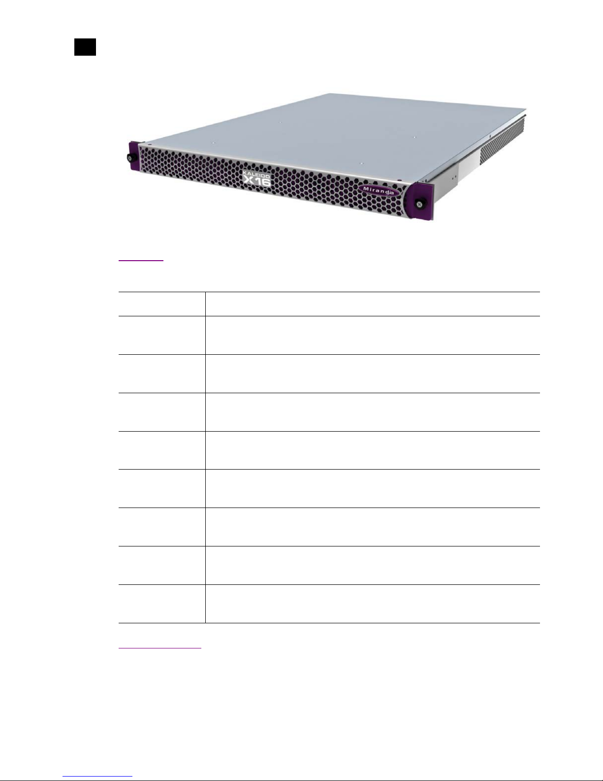
The Kaleido-X16 is a 1RU, multi-image display processor with high image quality and a
rich feature set. This chapter contains physical descriptions, installation instructions and
connection information for the Kaleido-X16 frame.
Summary
Introduction . . . . . . . . . . . . . . . . . . . . . . . . . . . . . . . . . . . . . . . . . . . . . . . . . . . . . . . . . . . . . . . . . . . . . . . . . . 1
Mechanical Installation . . . . . . . . . . . . . . . . . . . . . . . . . . . . . . . . . . . . . . . . . . . . . . . . . . . . . . . . . . . . . . . . . 5
Frame and Electrical Installation . . . . . . . . . . . . . . . . . . . . . . . . . . . . . . . . . . . . . . . . . . . . . . . . . . . . . . . . . 6
CompactFlash . . . . . . . . . . . . . . . . . . . . . . . . . . . . . . . . . . . . . . . . . . . . . . . . . . . . . . . . . . . . . . . . . . . . . . . . 12
Signalling . . . . . . . . . . . . . . . . . . . . . . . . . . . . . . . . . . . . . . . . . . . . . . . . . . . . . . . . . . . . . . . . . . . . . . . . . . . 12
Maintenance . . . . . . . . . . . . . . . . . . . . . . . . . . . . . . . . . . . . . . . . . . . . . . . . . . . . . . . . . . . . . . . . . . . . . . . . . 25
Introduction
The Kaleido-X16 system is a cost-effective multi-image processor. It can accommodate smaller systems or
scale up to production systems, where smaller building blocks with fewer input counts per display are
desirable. Each chassis can display up to 16 auto-sensing HD, SD, or Analog inputs that can be displayed
across two high resolution outputs at multiple sizes.
2
Kaleido-X16 Installation
Features
1
Features
Port Availability
The Kaleido-X16 offers a wide variety of ports for incoming and outgoing signals. However, with a view
towards future expansion, there are ports whose connections exist but that are currently not fully
Small form factor
1RU
Expandable
Expandable multi-room architecture, based on a chassis with 16 inputs, and
2 independent multi-image display outputs
Unmatched
flexibility
Any source can be repeated to any position, to any display, at any size, at any resolution,
without blocking or grouping restrictions
Kaleido-X16 as a
router
The Kaleido-X16 can behave as a router, with 16 input channels as sources and the two
RT OUT outputs as destinations
Superior display
Highest quality multi-image output without compression, with superior on-screen
graphics, for the most critical live monitoring applications
128 audio channels
Unprecedented audio performance with the ability to monitor up to 128 channels of
audio, including embedded, discrete analog, discrete AES from ABT
DVI inputs
DVI inputs (one per output head) mappable in the background of each output without the
need for scaling
Two-room layouts
Intuitive layout editor software allows rapid creation of two-room layouts, which can be
recalled quickly from networked remote control panels
Highly robust
Highly robust design, with multiple points of redundancy, andno single point of failure for
reliable 24/7 operation
Kaleido-X16
Hardware Description & Installation Manual
3
supported. The following ports on the Kaleido-X16 are not supported in the current release of the Kaleido-
X Software:
• OPTION streaming output connector
• PC In analog audio input ports at the AUDIO I/O connector
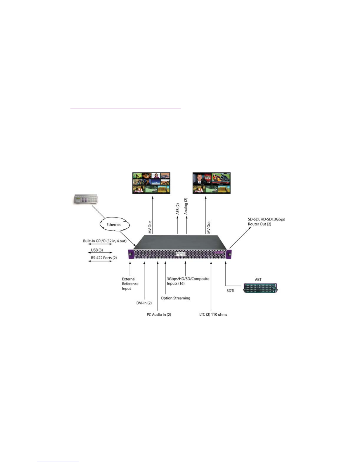
Overview of the Kaleido-X16 System
The following diagram shows a basic Kaleido-X16 system configuration, with a single Kaleido-X16 feeding
2 monitor wall displays. The Kaleido-RCP2 would be located on the production desk, while the Client PC
could be anywhere with Internet access to the network.
The diagram below shows a Kaleido-X16 system with its inputs and outputs. Examples of the various
external devices that connect to the Kaleido-X16 are also shown.
The Kaleido-X16 system is available in two model types: a single-head model (Kaleido-X16-S) and a dual-
head model (Kaleido-X16-D). Throughout this manual, Kaleido-X16 refers to both models unless it is
necessary to distinguish the single-head model from the dual-head model.
Kaleido-X16-D
There are two heads (Head 1 and Head 2) on the dual-head Kaleido-X16 (Kaleido-X16-D). The Input and
Output connections are as follows.

4
Kaleido-X16 Installation
Kaleido-X16-S
1
The rear connector panel for this model is displayed, below:
In addition to the difference in the number of output heads, the Audio I/O TBA pinout is different between
the two models (see “Audio I/O TBA” on page 16 for details).
Kaleido-X16-S
There is one head (Head 1) on the single-head Kaleido-X16 (Kaleido-X16-S). The Input and Output
connections are as follows.
The rear connector panel for this model is displayed, below:
In addition to the difference in the number of heads, the Audio I/O TBA pinout is different between the two
models (see “Audio I/O TBA” on page 16 for details).
Connector Number of connectors on Head 1 Number of connectors on Head 2
MV OUT 1 1
SDI OUT 1 1
DVI IN 1 1
Connector Number of connectors on Head 1
MV OUT 1
SDI OUT 1
DVI IN 1
No Head 2 connectors
(DVI IN2, SDI OUT2, MV OUT2)
Other manuals for Kaleido-X16
3
Table of contents
Other Miranda DVD Player manuals


