Miros SM-140 Series User manual

Summary:
The SM-140/02 RangeFinder is a unique high-performance remote sensor for measurement of air
gap, water level, draught and non-directional wave parameters. It utilizes a microwave radar-based
FMCW (Frequency Modulated Continuous Wave) sweep method for measuring air gap. When
delivered with the optional embedded MRU (Motion Reference Unit) to compensate for vessel
heave, the sensor is named SM-140 WaveFinder. For simplicity the name RangeFinder is used
throughout this document.
The sensor enables data to be easily accessible both locally and remotely using modern IoT
technologies.
The sensor is essential for several types of operations and can be integrated both with local and
remote systems. It can also be complimented with various value adding cloud services from Miros.
This manual provides information for installation, operation and user maintenance.
Revision No.
2
50 pages
Description:
Date
2018-12-19
Issued for information
Prepared by
Torbjørn Eide
Checked by
Gunnar Prytz
Approved by
Torbjørn Eide
RangeFinder
User manual
Project/Product
SM-140 - RangeFinder
Classification
Open

Blank page.

SM-140 - RangeFinder (User manual)
Miros AS
Page 3 of 50
Revision 2
TABLE OF CONTENTS
1Introduction 5
1.1 Warnings............................................................................................................................. 6
1.2 Abbreviations and definitions.............................................................................................. 6
1.3 Reference documentation................................................................................................... 7
1.4 How to contact Miros AS..................................................................................................... 7
2Quick start guides for advanced users 8
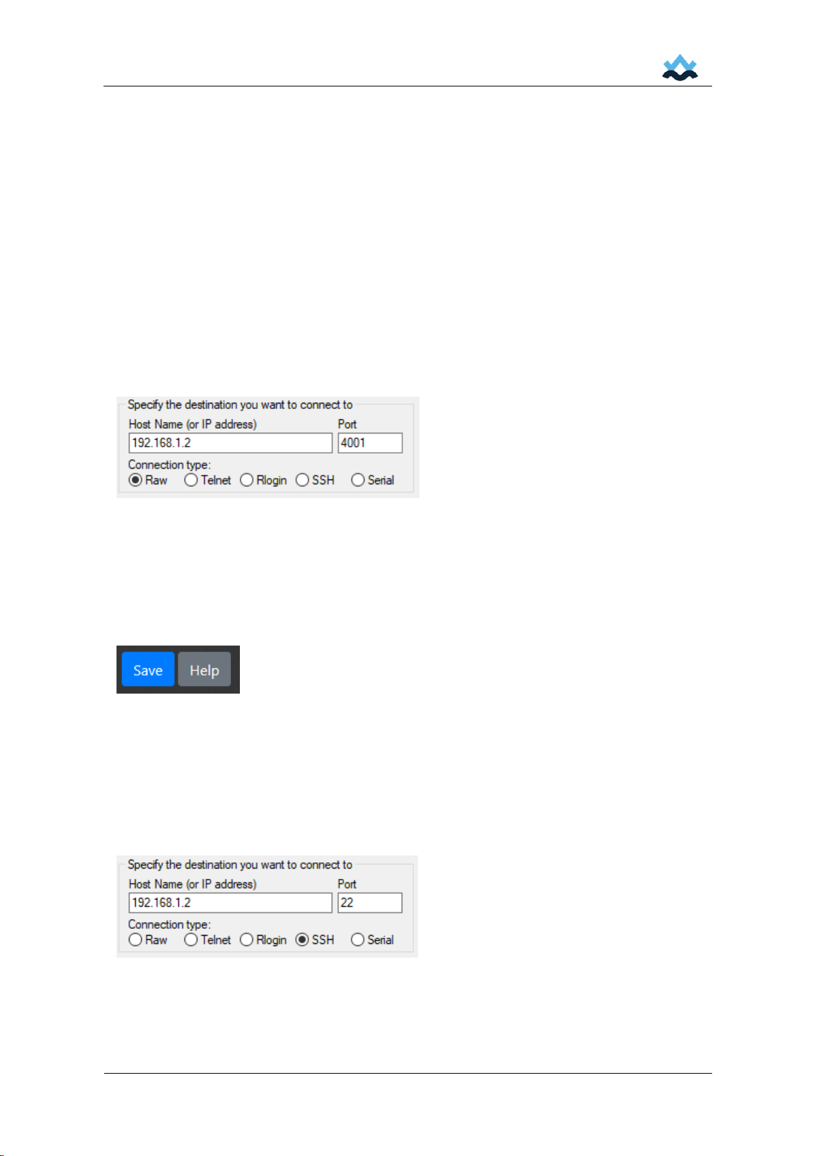
2.1 How to log on ...................................................................................................................... 8
2.2 How to get data (NMEA and/or SER formats) .................................................................... 8
2.3 How to configure using the Web GUI.................................................................................. 8
2.4 How to configure via the command line interface ............................................................... 8
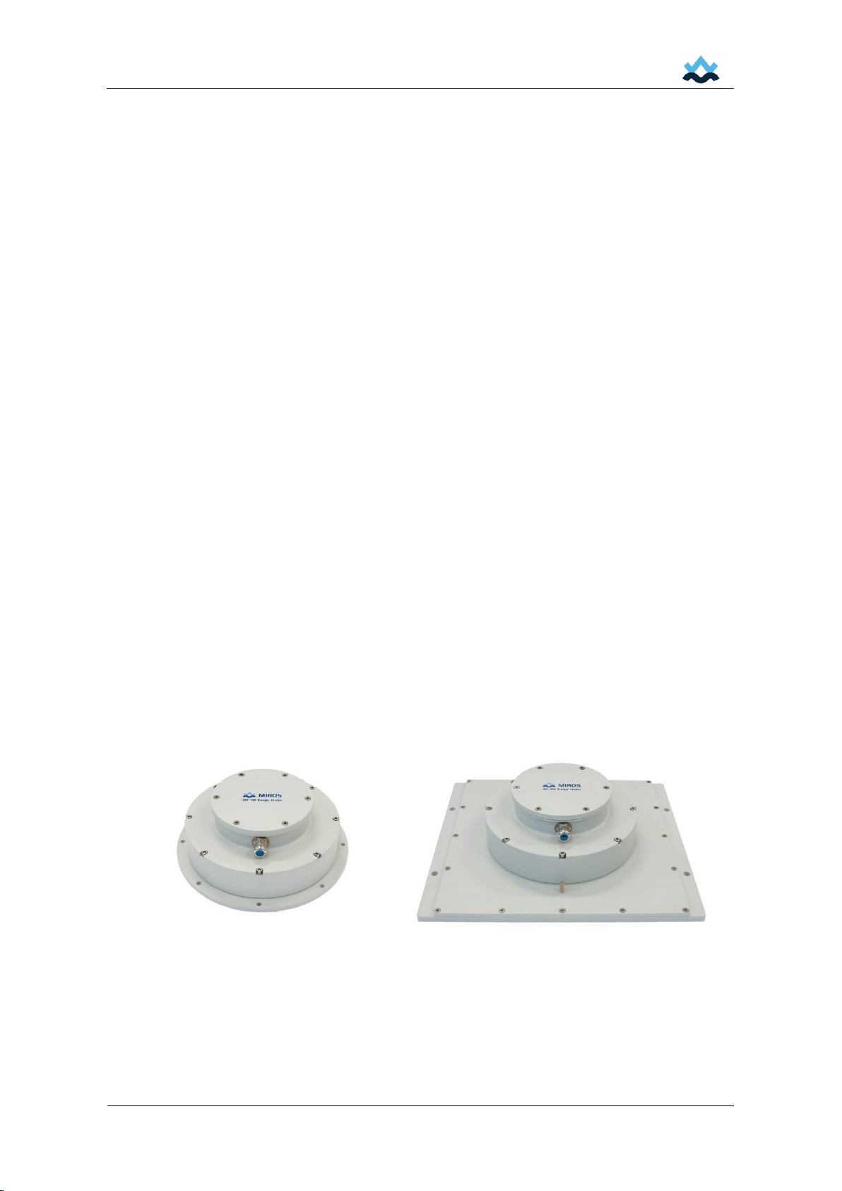
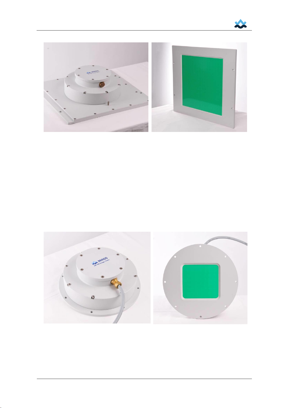
3Product overview 9
3.1 General description............................................................................................................. 9
3.3 Principles of operation....................................................................................................... 12
3.4 Sensor location and orientation ........................................................................................ 16
3.5 Mechanical installation...................................................................................................... 16
3.6 Electrical installation.......................................................................................................... 19
4Operation and configuration using local GUI 24
4.1 Start-up check................................................................................................................... 25
4.2 Overview tab ..................................................................................................................... 25
4.3 Wave tab........................................................................................................................... 26
4.4 WL + Draught tab.............................................................................................................. 27
4.5 Motion tab.......................................................................................................................... 28
4.6 Site configuration tab ........................................................................................................ 29
4.7 Network configuration tab ................................................................................................. 30
4.8 Output configuration tab.................................................................................................... 31
4.9 Time configuration tab....................................................................................................... 32
4.10 Wave configuration tab ..................................................................................................... 32
4.11 WL + Draught configuration tab........................................................................................ 33
4.12 Advanced configuration tab............................................................................................... 34
4.13 Display tab......................................................................................................................... 35
4.14 Firmware upgrade tab....................................................................................................... 35
5Maintenance 36

SM-140 - RangeFinder (User manual)
Miros AS
Page 4 of 50
Revision 2
5.1 Periodic inspections and maintenance ............................................................................. 36
5.2 Troubleshooting and repair............................................................................................... 36
5.3 Software upgrade.............................................................................................................. 36
6Technical data 37
6.1 Health, environment and safety ........................................................................................ 37
6.2 Performance data.............................................................................................................. 37
6.3 Electrical data.................................................................................................................... 38
6.4 Mechanical data................................................................................................................ 38
6.5 Interfaces........................................................................................................................... 38
6.6 Versions ............................................................................................................................ 38
6.7 Accessories and options ................................................................................................... 39
Appendix A Proprietary NMEA formats 40
A.1 PMIRWM –wave parameters........................................................................................... 40
A.2 PMIRWP –wave parameters from time series................................................................. 41
A.3 PMIRLD –wave spectrum ................................................................................................ 43
A.4 PMIRR –RangeFinder data.............................................................................................. 44
A.5 PMIRF –RangeFinder spectrum ...................................................................................... 46
A.6 PMIRW –RangeFinder water level and wave parameters............................................... 46
A.7 PMIRS –RangeFinder wave spectrum, water level and wave parameters ..................... 47
A.8 PMIRWD –RangeFinder water level, wave and draught parameters.............................. 48
A.9 PMIRM –RangeFinder motion.......................................................................................... 50

SM-140 - RangeFinder (User manual)
Miros AS
Page 5 of 50
Revision 2
1 Introduction
The SM-140/02 RangeFinder is a unique high-performance remote sensor for measurement of
air gap, water level, draught and non-directional wave parameters. It utilizes a microwave radar-
based FMCW (Frequency Modulated Continuous Wave) sweep method for measuring air gap.
When delivered with the optional embedded MRU (Motion Reference Unit) to compensate for
vessel heave, the sensor is named SM-140 WaveFinder. For simplicity the name RangeFinder
is used throughout this document.
Typical areas of application are:
•Air gap and draught
•Ocean wave profiles and tidal variations
•Motion compensated wave monitoring (ship-borne system)
•Water level in dams, rivers, canals and lakes
•Bridge clearance
The sensor is available in four versions:
•SM-140/W/02 RangeFinder with wide beam (range 1 m - 23 m)
•SM-140/WWF/02 WaveFinder with wide beam (range 1 m - 23 m)
•SM-140/N/02 RangeFinder with narrow beam (range 3 m - 95 m)
•SM-140/NWF/02 WaveFinder with wide beam (range 3 m - 95 m)
The sensor enables data to be easily accessible both locally and remotely using modern IoT
technologies.
The sensor is essential for several type of operations and can be integrated both with local and
remote systems. It can also be complimented with various value adding cloud services from
Miros.
This manual provides information for installation, operation and user maintenance.
Wide beam model SM-140/W/02
Narrow beam model SM-140/N/02
Figure 1.1 SM-140 RangeFinder

SM-140 - RangeFinder (User manual)
Miros AS
Page 6 of 50
Revision 2
1.1 Warnings
Although the SM-140 RangeFinder is constructed for measurements in a harsh environment, it
is a delicate instrument and will operate according to specifications only if installed and treated
properly and in accordance with this user manual.
Do not attempt to dismantle the unit. The sensor is a precision instrument and shall not be
subject to field service by operator's personnel unless pre-approved by Miros. Do not modify or
substitute parts in the instrument. Contact Miros Support or Miros’ representative for repairs.
Do not operate the equipment in the presence of flammable gases or fumes. Operation of any
electrical instrument in such an environment constitutes a definite safety hazard. The sensor
must be installed in a safe area or shut down in presence of an explosive gas atmosphere.
1.2 Abbreviations and definitions
Term
Explanation
ARM processor
An ARM processor is one of a family of CPUs (Central Processing Unit)
based on the RISC (Reduced Instruction Set Computer) architecture
developed by Advanced RISC Machines (ARM)
BB
Baseband
Beat (frequency)
A beat is an interference between two signals of slightly different
frequencies, perceived as periodic variations in signal strength whose
rate is the difference between the two frequencies.
The beat frequency is used for analyzing transmitted and received echo
signal in the sensor.
Capillary wave
A capillary wave is a small, free surface-water wave with such a short
wavelength that its restoring force is the water’s surface tension.
Capillary waves are often referred to as ripples
Chirp
Chirp is a signal in which the frequency increases
('up-chirp') or decreases ('down-chirp') with time
COC
Certificate of Conformance (part of shipment)
DDS
Direct Digital Synthesizer (DDS) is a type of frequency synthesizer used
for creating arbitrary waveforms from a single, fixed-frequency reference
clock.
FMCW
Frequency Modulated Continuous Wave –a distance measurement
principle used by radars
GUI
Graphical User Interface
Hamming Window
A mathematical function optimized to minimize the maximum (nearest)
side lobe
IEC
International Electrotechnical Commission
IF
Intermediate Frequency
IP
IP address
Ingress Protection
Numerical label assigned to each device connected to a network
IQ-mixer
Quadrature IF Mixer. It provides two IF signals with equal amplitudes
which are in phase quadrature. Used in generating the beat frequency
Microwave
Electromagnetic wave in the range of 0.0001 –0.3 m
MRU
Motion Reference Unit
NMEA or NMEA 0183
Combined electrical and data specification for communication
PE
Protective Earth
PLL
Phase Locked Loop. An electronic circuit consisting of a variable
frequency oscillator and a phase detector that generates an output
signal whose phase is related to the phase of an input "reference" signal.
RS-232
(EIA-232) communication standard for single-ended data transmission

SM-140 - RangeFinder (User manual)
Miros AS
Page 7 of 50
Revision 2
RS-422
(EIA-422) communication standard for differential data transmission,
multi-drop
TCP/IP
Transmission Control Protocol/Internet Protocol, a common connection-
oriented communication protocol
1.3 Reference documentation
[1] SM-140/001/DR SM-140/W/01 RangeFinder - General arrangement
[2] SM-140/009/DR SM-140/N/01 RangeFinder - General arrangement
[3] SM-140/02 RangeFinder - Data sheet
[4] SM-140/02 WaveFinder - Data sheet
[5] SM-140/006/DD SM-140 - EC Declaration of Conformity (CE Marking)
1.4 How to contact Miros AS
Norway
Corporate headquarters
Miros AS
Solbråveien 20
NO-1383 Asker
Norway
Phone: +47 66 98 75 00
Fax: +47 66 90 41 70
E-mail: off[email protected]
www.miros-group.com
UK
Miros Scotland Ltd.
Aberlan House. Woodburn Road
Blackburn Industrial Estate
Aberdeen AB21 0RX
United Kingdom
Phone: +44 1224 791 222
Fax: +44 1224 791 555
E-mail: uk@miros-group.com
Service & Support
Phone: +47 66 98 75 00
UK
Phone: +44 1224 791 222
E-mail: support@miros-group.com
www.miros-group.com/service-support

SM-140 - RangeFinder (User manual)
Miros AS
Page 8 of 50
Revision 2
2 Quick start guides for advanced users
This chapter contains information for advanced users. For non-skilled users it is recommended
to read the complete user manual.
2.1 How to log on
Default IP address: 192.168.1.2 (or as stated on COC following the shipment)
If IP address is not known, connect to J11 Service port (RS232 115200,n,8,1).
At command prompt (RangeFinder>) type config network wired to obtain the configured IP
address.
2.2 How to get data (NMEA and/or SER formats)
Connect to TCP/IP port 4001 using e.g. PuTTY.
2.3 How to configure using the Web GUI
•Configure site parameters (including Application type)
•Configure output
Change the appropriate settings and click save. A simple online help/guideline is shown when
clicking the help button.
When prompted for credentials please enter the following:
Username: admin
Password: admin
2.4 How to configure via the command line interface
Use the J11 Service port (RS232 115200,n,8,1) or connect via TCP/IP port 22 on the Ethernet
interface.
Type help to list commands/command groups. Type command group to list sub-commands etc.,
e.g. config or config site. To change a parameter, add a value to the command/sub-command,
e.g. config site height 30 to set sensor mounting height to 30 m.

SM-140 - RangeFinder (User manual)
Miros AS
Page 9 of 50
Revision 2
3 Product overview
3.1 General description
The Miros SM-140 RangeFinder is a microwave radar-based sensor operating at 9.6 GHz
centre frequency. It uses the FMCW principle to measure the vertical distance from the sensor
antenna to the water surface.
The sensor is available in four versions:
•SM-140/W/02 RangeFinder with wide beam (range 1 m - 23 m)
•SM-140/WWF/02 WaveFinder with wide beam (range 1 m - 23 m)
•SM-140/N/02 RangeFinder with narrow beam (range 3 m - 95 m)
•SM-140/NWF/02 WaveFinder with wide beam (range 3 m - 95 m)
Typical applications are tide and wave measurements from onshore and offshore installations
and bridge clearance measurements.
Figure 3.1 Wave measurements onboard ships and tide measurements are typical
Miros RangeFinder applications
The SM-140 RangeFinder emits a frequency modulated, continuous wave (FMCW or chirp)
microwave signal and receives an echo from the water surface. The signal propagation delay
given by the distance from the antenna to the water surface causes a beat (interference pattern)
between the transmitted and received signal. The beat signal frequency, which is proportional to
the distance, is measured and converted to an accurate distance by the RangeFinder.
The 9.6 GHz operating frequency makes the SM-140 RangeFinder less sensitive to unwanted
influence from fog, rain and water spray than microwave sensors operating at higher
frequencies and laser-based sensors. This can be of importance particularly for the longer-
range applications.
The planar patch antennas result in small physical dimensions and low weight. The SM-140/W
wide antenna version has a beam-width of 10 degrees while the SM-140/N narrow version has
5 degrees beam-width.

SM-140 - RangeFinder (User manual)
Miros AS
Page 10 of 50
Revision 2
SM-140/N rear view
SM-140/N front view (antenna side)
Figure 3.2 SM-140/N RangeFinder
The SM-140 RangeFinder has a wide range of user selectable signal processing, detection and
tracking parameters. By proper parameter settings the sensor performance can be optimised for
different applications.
The digital signal output may either be continuous at a user selectable rate, or single
measurements in response to user request. The sensor transmits Miros proprietary NMEA
formats over TCP/IP port 4001.
The old SER formats may also be selected by the user for compatibility with previous models of
the Miros SM-140 RangeFinder.
SM-140/W rear view
SM-140/W front view (antenna side)
Figure 3.3 SM-140/W RangeFinder

SM-140 - RangeFinder (User manual)
Miros AS
Page 11 of 50
Revision 2
A simplified functional block diagram of the SM-140 RangeFinder is shown in figure 2.4.
The microwave FM sweep is generated by the FMCW transceiver using direct digital frequency
synthesizer (DDS). A DDS has many advantages over its analogue counterpart, the PLL; much
better frequency agility, improved phase noise, and precise control of the output phase across
frequency switching transitions.
Figure 3.4 SM-140 RangeFinder functional block diagram

SM-140 - RangeFinder (User manual)
Miros AS
Page 12 of 50
Revision 2
3.3 Principles of operation
Air gap or range (distance) measurements
The SM-140 RangeFinder emits a frequency modulated continuous wave (FMCW or chirp)
microwave signal and receives an echo from the water surface. The signal propagation delay
given by the distance from the antenna to the water surface causes a beat between the
transmitted and received signal. The beat signal frequency, which is proportional to the
distance, is measured and converted to an accurate distance by the RangeFinder.
The FMCW chirp signal is generated by a direct digital frequency synthesizer (DDS) with
absolute frequency linearity and high stability. The sensor therefore provides accurate range
measurements and high long-term stability. Due to the low frequency of operation (compared to
laser sensors), fog, rain and water spray will not cause measurement problems.
The transmitted microwave signal is modulated with triangular frequency modulation. The echo
received from a target (e.g. the sea surface) will be a delayed replica of the transmitted signal. A
beat frequency is generated by mixing the transmitted and received signals, using an IQ-mixer.
This frequency is a linear function of delay, or distance to the target (reflecting object) as
illustrated in figure 2.8.
Figure 3.5 SM-140 FMCW signal principles
The beat frequency is derived by means of FFT analysis. A Hamming window ensures proper
range side-lobe attenuation.
The range cell or range increment is determined by the FMCW sweep bandwidth. A sweep
bandwidth of 400 MHz gives a range increment of 374.63 mm which is independent of the
sensor range. The sensor unambiguous range is the theoretical maximum range for a given
FMCW waveform. The sensor range must for practical reasons be slightly less than the
unambiguous range. The number of range cells required to cover the sensor range is
automatically calculated.
Time
Frequency (GHz)
F/2
-F/2
Frequency of transmitted
signal is swept between -F/2
and F/2
Frequency of received
signal is a delayed replica of
transmitted signal
Delay τ
Beat frequency fb
Sweep time Ts
Sweep bandwidth
Time
Frequency (GHz)
F/2
-F/2
Frequency of transmitted
signal is swept between -F/2
and F/2
Frequency of received
signal is a delayed replica of
transmitted signal
Delay τ
Beat frequency fb
Sweep time Ts
Sweep time Ts
Sweep bandwidthSweep bandwidth

SM-140 - RangeFinder (User manual)
Miros AS
Page 13 of 50
Revision 2
FFT range cell number
Figure 3.6 Typical beat signal time series (left) and FFT output (right)
A typical beat signal time series (after Hamming weighting) is shown in figure the left, and the
corresponding FFT output to the right. Two peaks are shown, the second peak corresponds to
the second time around echo.
The range accuracy is improved by interpolation. Starting with the FFT array of N range cells
the range estimation process may briefly be described as follows:
1. Find the peak value (range cell number and amplitude)
2. If the signal amplitude is above an absolute threshold (parameter Minimum level),
check the detection level (parameter Threshold, % of peak value)
3. Find the range cell corresponding to the shortest range with amplitude equal to or
above the Peak Value x Detection Level (and above threshold level)
4. Determine the range by interpolation between adjacent range channels and by adding
a fixed internal range offset (established by calibration)
Note The standard configuration setting for threshold value Minimum level is 50, and
Threshold (detection level) 100 %. The values can be manipulated by advanced user to
suit special purposes (e.g. if only a certain signal level shall be processed). Range cells
outside a predetermined range can be neglected for applications that shall work within a
restricted range.
Figure 3.7 Range tracking window
0100 200 300
400−
200−
0
200
400
Sample number
Amplitude in internal units
sn
n
050 100 150
0
200
400
600
800
1103
FFT bin number
Amplitude in internal units
Sn
n

SM-140 - RangeFinder (User manual)
Miros AS
Page 14 of 50
Revision 2
The effect of multi-path, fading and multiple time around echoes are counteracted by means of
a range tracking window, see figure 3.7. The centre of the window is determined by low-pass
filtering of the measured range values. Both the time constant of this filter and the width of the
tracking window may be selected by the user. If the measured range falls within the tracking
window the value is used as an output. If the value is outside the window the distance will be set
equal to the last accepted value for a defined time-out period (defined by Time constant). This is
to indicate an error, and the Error value (user defined). The RangeFinder will then start to
calculate a new tracking window position using all measured values.
If the level of the signal reflected from the sea surface falls below the minimum signal level a
user defined time-out count is also started. After the time-out the air gap (range) output is set to
0.00 m to indicate an error.
Wave parameters from spectrum
When the sensor is used for non-directional wave measurements, the air gap data is processed
into a wave spectrum. Wave parameters, wave height and periods, are derived from the wave
spectrum.
The air gap in meters is sampled at 2, 4 (default) or 10 Hz over a 128 s (default) or 256 s period,
also knows Observation time. The spectrum frequency resolution is thus
1/Observation time = 1 / 128 s = 0.0078 Hz (or 1 / 256 s = 0.0039 Hz)
Figure 3.8 The distances are sampled at 2 Hz over 128 s periods
The FFT analysis will provide a wave spectrum as shown in figure 3.9, split up into "64 wave
bins". The area under the curve for each bin represents the energy for this period.
Each wave bin represents a wave period, e.g. for frequency bin no. 4 and 0.0078 Hz resolution:
Wave period =
1
=
1
= 32 s
Freq bin x resolution
4 x 0.0078 Hz
Similarly, wave bin 26 represents the mean wave period of 5 s.

SM-140 - RangeFinder (User manual)
Miros AS
Page 15 of 50
Revision 2
The following spectrum is based on
Significant wave height Hm0 = 3 m
Mean period Tm02 = 5 sec
Peak period is in wave bin 17 (7.5 s).
Figure 3.9 Wave spectrum calculated using Welsh method,
based on time-series segments of 256 samples (2 Hz/128 seconds)
For wave parameters calculated from the wave spectrum, refer to Appendix A.
Wave parameters from time series
Wave parameters are also calculated directly from the time series (fig. 3.8) by identifying the
zero-crossings (after detrending and interpolation). Before calculating the individual wave
periods (1/cycle), heights, crests and troughs, wavelets (small capillary waves) are ignored.
Figure 3.10 Wave profile
For wave parameters calculated directly from the wave time series, refer to Appendix A2.

SM-140 - RangeFinder (User manual)
Miros AS
Page 16 of 50
Revision 2
3.4 Sensor location and orientation
The installation site for the SM-140 RangeFinder must be carefully selected. This is important
to collect high quality measurements. For mechanical details please see the general
arrangement drawings.
The following must be considered:
•The SM-140 RangeFinder should be mounted on a suitable support structure with an
open vertical view of the water surface, e.g. at the bow of the vessel or on the outside
of a bridge or platform handrail. See figure 3.11 for distance requirements
•Reflecting objects should not be present in the near vicinity of the SM-140
RangeFinder, to avoid problems caused by multi-path signal propagation
•The location should be accessible for periodical cleaning and service
•The instrument's measuring range is a determining factor for finding the optimum
installation height
•The sensor is not certified for use in explosive atmospheres
Figure 3.11 Make sure there is an open view from the RangeFinder
Xmin = Y * tan (/2)
3.5 Mechanical installation
Although the sensor is constructed for measurements in a harsh environment, it is an instrument
that must be handled with care during all phases of the installation. Make sure that the surface
of the housing and antenna are free from mechanical defects and scratches.
The important mounting details are shown in following pages. See figure 3.2 for the SM-140/W
Wide Beam and figure 3.3 for the SM-140/N Narrow Beam RangeFinder. For further details see
general arrangement drawings.
Note! Miros recommends use of the MP-404 Bolting Kit for proper installation. The
bolting kit includes necessary bolts, insulation washers and sleeves for a
four-hole fixation.
Miros MP-327 Mounting Bracket is available as option for easy installation to a handrail or
similar.

SM-140 - RangeFinder (User manual)
Miros AS
Page 17 of 50
Revision 2
The sensor is typically installed with a short cable to a local junction box. This will ensure
optimum service accessibility.
The SM-140 RangeFinder should preferably be installed with cable tail fitted. This is to avoid
ingress of humidity or particles through the gland opening. Further, the cable terminals are
generally less accessible after unit has been installed at site. Use sealant tape or heat shrink
sleeve to seal off the other cable end until it is terminated in a junction box or similar.
If a cable tail is not fitted, make sure the gland opening is sealed off until the electrical
installation shall take place.
Use tarpaulin or fiber glass reinforced fabric and tape to protect equipment from construction
site activities, if unit is not put immediately into operation.
The mounting bracket must have a
free opening slightly greater than the
antenna aperture (180x170 mm).
The housing is made from aluminium.
When mounted to a steel structure the
unit should be galvanically insulated
from the structure to avoid galvanic
corrosion.
There are eight holes Ø10.3 mm
equally spaced on a bolt circle
diameter Ø320 mm. These are used
for bolting to a mounting frame or
bracket. Four bolts equally spaced will
provide a proper installation. The
excessive number of mounting holes
is made for increased flexibility. Use
Nylon washers and sleeves to ensure
proper insulation of materials.
Neoprene or rubber gaskets and
sleeves may be used as alternative
insulation materials.
The SM-140 RangeFinder is fitted
with an M8 earth stud for bonding to
the structure.
Cable entry is via a M20 cable gland
from the side.
Cable OD 5 - 14 mm
(9 - 14 mm without inlet insert).
Figure 3.12 Mechanical installation - SM-140 wide beam RangeFinder

SM-140 - RangeFinder (User manual)
Miros AS
Page 18 of 50
Revision 2
The mounting bracket must
have a free opening slightly
greater than the antenna
aperture (340x340 mm).
The housing is made from
aluminium. When mounted
to a steel structure the unit
should be galvanically
insulated from the structure
to avoid galvanic corrosion.
There are four mounting
holes Ø10.3 mm for bolting
to a mounting frame or
bracket. Use Nylon washers
and sleeves to ensure
proper insulation of
materials.
Neoprene or rubber gaskets
and sleeves may be used as
alternative insulation
materials.
The RangeFinder is fitted
with an M8 earth stud for
bonding to the structure.
Cable entry is via a M20
cable gland from the side.
Cable OD 5 - 14 mm
(9 - 14 mm without inlet
insert).
Figure 3.13 Mechanical installation - SM-140 narrow beam RangeFinder

SM-140 - RangeFinder (User manual)
Miros AS
Page 19 of 50
Revision 2
3.6 Electrical installation
Do not power up the SM-140 RangeFinder as part of the electrical installation work. Powering
up of equipment shall follow the installation's commissioning plan. Make sure power is off or
SM-140 RangeFinder is disconnected from the central equipment when terminating the sensor
cable.
Caution! An external T2A overcurrent protector is mandatory for installations in compliance
with the CE marking requirements.
The SM-140 RangeFinder is normally installed with a short cable to a local junction box. Miros
recommends that an external T2A overcurrent protector (fuse) is mounted in the local junction
box. The fuse must be designed according to IEC 60127-2.
The following installation material is approved for use.
Object
Manufacturer/
trademark
Type/model
Technical
data
Standard
Conformity
marks
External
fuse
(overcurrent
protector)
Littelfuse
213
T2A, 250V,
5x20mm
(2A, time-lag)
IEC 60127-2
UL248-14
UR, CSA,
S, VDE,
CCC
External
fuse holder
Phoenix
Contact
UT 4-HESI,
UT 4-HEDI (-P /P)
5x20mm 500V
/
6.3A, 94V-0
IEC 6950-1,
UL1059, UL486,
ANSI/UL 60947-7-3,
IEC 60947-7-3
UR,
E60693
External
fuse holder
(alternative)
Weidmuller
WSI 6
5x20mm 500V
/
6.3A, 94V-0
IEC 6950-1,
UL1059, UL486,
ANSI/UL 60947-7-3,
IEC 60947-7-3
UR,
E60693
Table 1: Approved installation material

SM-140 - RangeFinder (User manual)
Miros AS
Page 20 of 50
Revision 2
Access to SM-140 RangeFinder terminals is provided by removing the top lid. Use an M6 hex
key (Allen key/Unbrako). It is not necessary to access the terminals for SM-140 Rangefinder’s
supplied with a cable tail at delivery.
Figure 3.14 Cable termination chamber (see next page for signal description)
Electrical connection
Electrical connection is through a ThoughCat 5e (or better) Ethernet cable (combined power
and signal cable).
The SM-140 RangeFinder is normally installed with a short cable to local junction box.
A cable tail (CA-383) can be supplied on request in appropriate length (Draka ThoughCat 5e
S/FTP LSHF-FR or equivalent). This is a four pair cable to be terminated in a local junction box
or similar. Optionally a four pair BFOU cable can be used for serial communication.
Open top lid for access to terminals. The terminals are part of the EU-051 Connector Unit, with
signal description as shown on the next page.
This manual suits for next models
3
Table of contents
Popular Measuring Instrument manuals by other brands

Siemens
Siemens SENTRON PAC5200 Device manual

PCB Piezotronics
PCB Piezotronics IMI SENSORS Platinum Swiveler ICP... Installation and operating manual

PCB Piezotronics
PCB Piezotronics J351B31 Installation and operating manual

Mantracourt
Mantracourt X24 user manual

Dranetz
Dranetz DBPVFLEX6K user guide

Omega
Omega CN1001-TC user guide