3:COLD
-
+
1:GND
2:HOT
3
21
4 5
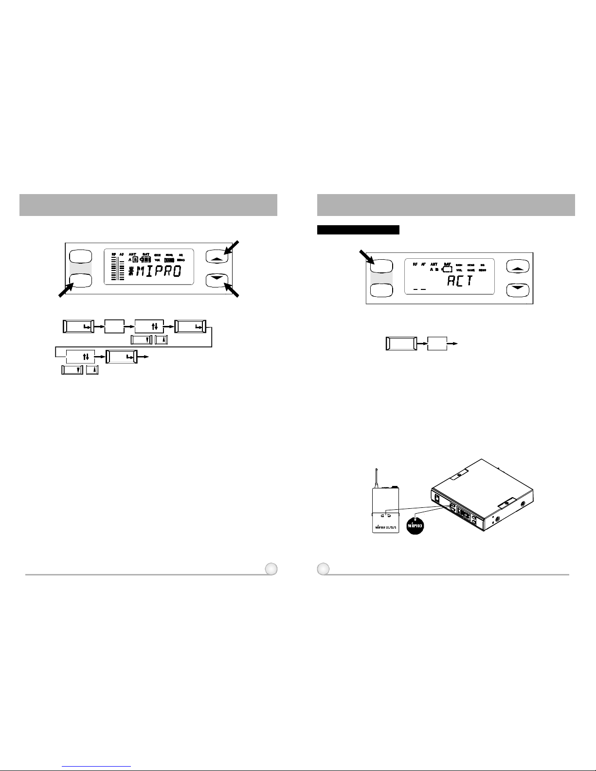
ACTSINGLECHANNELWIRELESSRECEIVERACTSINGLECHANNELWIRELESSRECEIVER
(Fig.3)
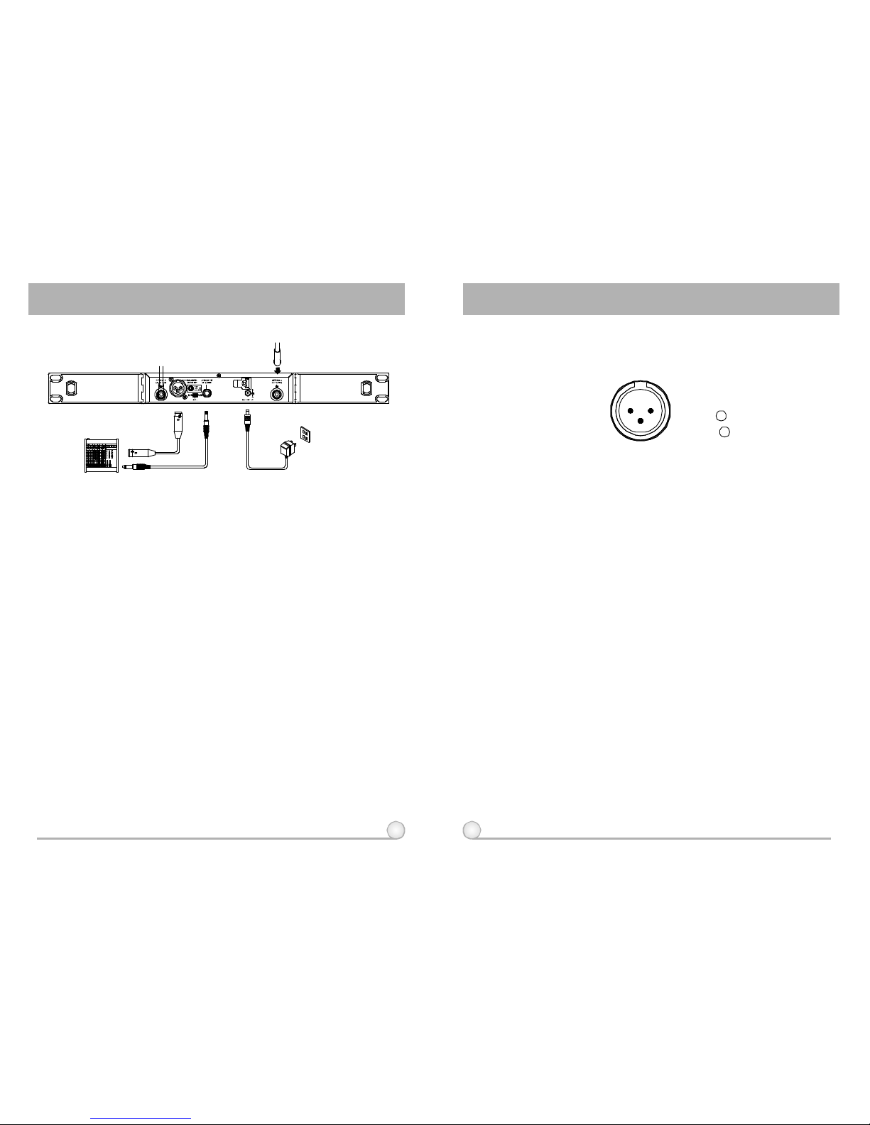
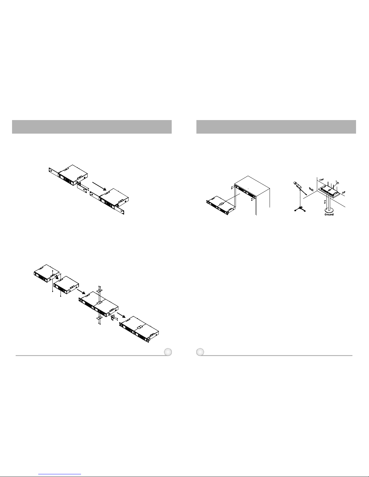
3.INSTALLATIONOFTHERECEIVER
1.Install2separateantennasontheantennasockets(5),(10)ontherear
panel.Illustratedinfigure3.
2.Connectingthepowersupply:
3.AudioOutputConnection:
ConnecttheAC/DCadaptercabletoDC
12VINPUTJACK(9),thenplugtheadapterunitintoanappropriateAC
outletwithcautiontothecorrectvoltageunderbothACoutletand
adaptermarked.Illustratedinfigure3.
(a)UnbalancedLevelSwitch(7)SettingPosition:Wheninputstheunbalanced
outputofareceiverinto"AUX-IN"inputjackofamixeroramplifieror"Electric
Guitar",switchtheLevelSwitch(7)totheright"LINE"position.Low
sensitivitymayoccurifswitchtothewrongposition.Wheninputthe
unbalancedoutputofareceiverintothe"MIC-IN"inputjackofamixeror
amplifier;switchtheLevelSwitch(7)totheleft"MIC"position.Overload
distortionmayoccurifswitchtothewrongposition.Whenusingelectricguitar,
don'tuse"MIC"positionasitmayhavegeneratedinsufficientlevel.
(b)UnbalancedOutput:Usingaudiooutputcableattachedwith"PHONEPLUG"
type,connectoneendfromtheunbalancedoutputjack(8)ofthereceiver,
andtheotherendtothe"LINE-IN"inputjackoftheamplifier,asshowninFig.
3.
(c)BalancedOutput:Usingaudiooutputcablesattachedwith"XLR"or
"Cannon"type,connectoneendfromthebalancedoutputjacks(6)ofthe
receiver,andtheotherendtothe"MICIN"inputjackofthemixeror
amplifier,asshowninFig.3.(Thecharacteristicofthe3-pinconnectoris
asshowninFig.4
(Fig.4)
(d)GuitarOutput:Usingaudiooutputcableattachedwith"PHONEPLUG"type,
plugoneendfromtheunbalancedoutputjackofareceiver,andtheother
endtotheinputjackofaguitaramplifier.SwitchtheLevelSwitch(7)to
"LINE"position.
4.AntennaSocket:Theantennasocketprovides8VoltDCpower,which
enableyoutopairwithMIPRO'santennaboosterdirectly.Whenthe
connectingcablefortheantennaismorethan10meter,itis
recommendedtoinstallantennaboostertomakeupthesignalloss
causedbythecableandtoensurethesensitivityofreception.
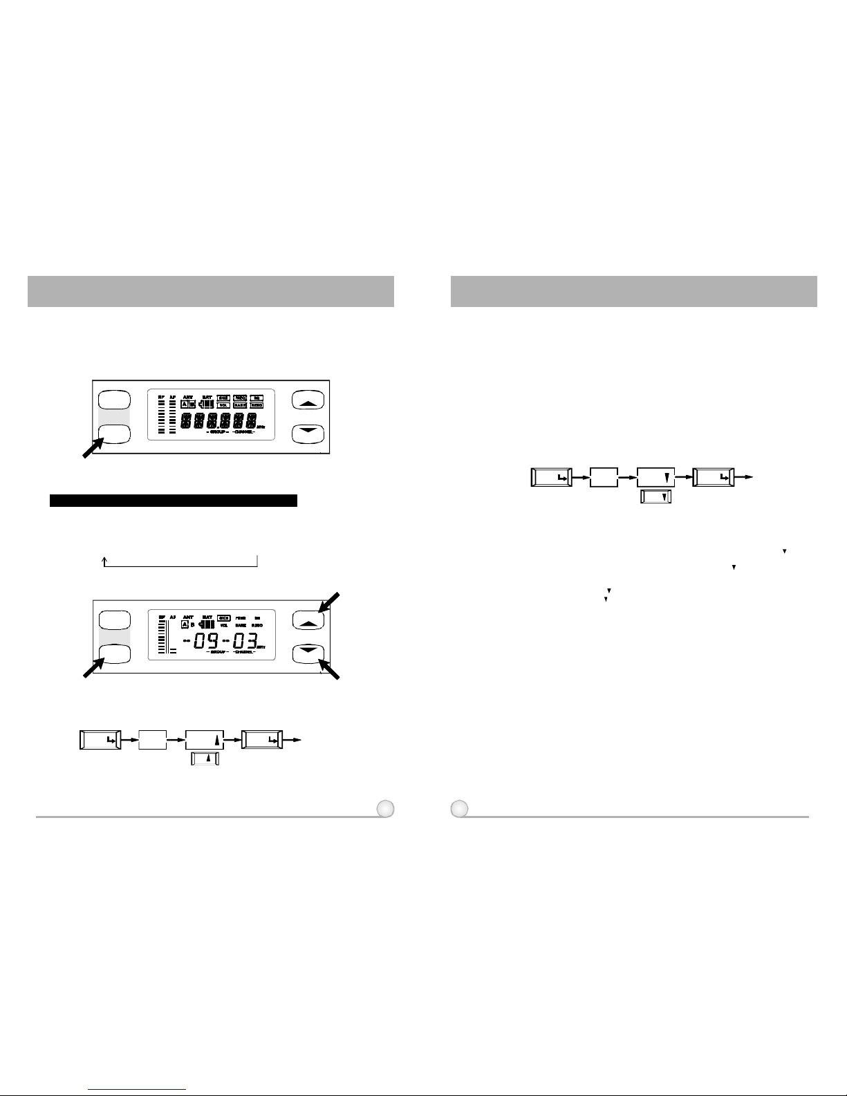
4.RECEIVEROPERATINGPROCEDURES
1.Turnvolumecontrolsofthemixerinusetoaminimumsettingbeforeturn
onthemicrophonesortransmitters.Afterswitchesonthereceiver,the
powerswitchredindicatorilluminatestodenotenormalpowerstatus.
2.Undernormalcircumstances,theRFindicatorlightsupwhena
microphoneortransmitteristurnedonnearthereceivertoindicatethe
receiverisreadyfornormaloperation.Oncesoundstothemicrophone
andtheAFindicatorswillglowaccordingtothestrengthofsoundlevel.
IfnoLEDglowsornosoundoutputs,thesystemisnotfunctionproperly,
thusitmustbechecked
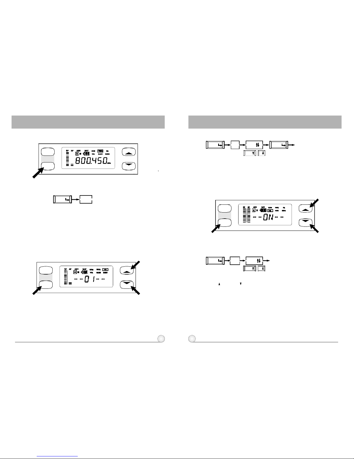
3.Themicrophoneoutputlevelneedstobeadjustedattheamplifieror
mixer.Noneedtoadjustatthereceiveritself.