Misterstep GAMIA WOOD User manual

GAMIA WOOD
ISTRUZIONIDIPOSA
ASSEMBLYINSTRUCTIONS
INSTRUCTIONSDEMONTAGE
INSTRUCCIONESPARALACOLOCACION
MONTAGEANLEITUNG
INSTRUÇÕESDEINSTALAÇÃO


Italiano
Descrizione
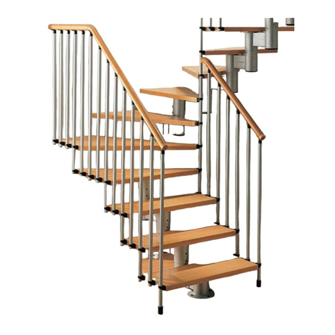
Scala a chiocciola modulare in metallo/legno a pianta circolare regolabile in altezza tramite distanziatori metallici
interposti tra i gradini.
Nr. gradini e altezze raggiungibili per scale "filo-pavimento"
11 + 1 gradini : 2520 - 2760 mm
12 + 1 gradini : 2730 - 2990 mm
13 + 1 gradini : 2940 - 3220 mm
Gradini
Di faggio fingerjoint, spessore 38 mm . Gradini semplici (30°) e pianerottolo di arrivo “Universale”.
Alzate
Standard Min. 210 mm ; Max 230 mm (per alzate 200 ÷ 210 mm; 230 ÷ 240 mm si possono adattare le colonne in
fase di posa).
Ringhiera
A colonne in tubo di metallo Ø 22 mm (luce max tra le colonne < 100 mm). Corrimano di materiale plastico
flessibile (ht. corrimano = 1 m).
Finitura e colori
Parti di legno: tonalizzate con vernice all’acqua (Naturale 12/Noce 16)
Parti di metallo: verniciate a forno con polveri epossidiche (Nero goffrato/Grigio Argento).
Componenti in plastica, gomma e viteria: nero/grigio.
NOTE PER LA POSA
Prima di procedere con la posa:
- verificare le dimensioni del vano scala;
- controllare che, nelle zone dove verranno effettuati i fissaggi della scala, non vi siano tubature o cavi elettrici,
onde evitarne il danneggiamento;
- verificare la capacità di carico del pavimento
1) Assemblare il palo nella sequenza indicata bloccando saldamente gli elementi fra loro, facendo leva con un
perno negli appositi fori dei tubi.
2) Posizionare il palo in riferimento al foro, disponendo il gradino di arrivo sul lato di uscita della scala.
Verificare l’esatta perpendicolarità al pavimento. Prima di bloccare lo sbarco, assicurarsi della sua perfetta
orizzontalità utilizzando una livella. Prima di segnare la posizione dei fori della piastra del palo centrale sul
pavimento, bloccare temporaneamente il gradino di sbarco per evitare spostamenti ed errori di misurazione. In
caso di pavimenti/travi in legno utilizzare solo mordenti/viti da legno per sostituire quelle fornite, adatte solo per
cemento armato.
3) Regolare i distanziali in plastica avvitando la ghiera filettata, lasciando tra le due battute una distanza pari a
“Alzata - 160 mm”. E’ poi necessario aumentare l'altezza con mezzo giro in meno sul distanziale al fine di
recuperare la compressione sul filetto della vite (tolleranza) in fase di serraggio di tutti i gradini.
N.B. Per la 1° alzata occorre tenere conto della piastra del palo centrale e dell'interferenza dovuta alla saldatura
piastra –palo.
4) Inserire gli elementi nel palo iniziando dal copripiastra in basso, proseguendo con distanziali e gradini, sino
all’inserimento del gradino di arrivo.
"2015©Rintal S.r.l. –Tutti i diritti riservati-All rights reserved”
1
FM_GAMIA-WOOD_R7_12/2015

5) Posizionare il pianerottolo di arrivo. Tagliare il gradino di sbarco universale in funzione della forma dl foro. In
caso di pavimenti/travi in legno utilizzare solo mordenti/viti da legno per sostituire quelle fornite, adatte solo per
cemento armato.
6) Inserire nel palo la flangia terminale, la barra filettata ed il terminale, quindi avvitare con il dado, in modo da
comprimere la scala, ma lasciando ai gradini la libertà di ruotare.
7) Comporre il raccordo “'Novia” assemblando gli elementi. Per l’assemblaggio dei componenti in plastica
utilizzare sempre del grasso lubrificante.
8) Inserire le colonne in tutti i gradini, bloccando quelle passanti con i grani e quelle sul gradino con la boccola ad
espansione “Espa”. Bloccare bene l’inserto in plastica nella boccola di plastica prima di inserirlo nelle colonnine.
Non avvitare troppo a fondo il grano perché potrebbe danneggiare la colonna durante il suo inserimento nel foro.
Non serrare completamente i grani delle colonne passanti prima di aver terminato il serraggio della scala
completa. Completare il serraggio solo dopo aver avvitato completamente la barra filettata M22 con il dado.
9) La prima colonna della scala va tagliata e fissata a terra tramite il “Bicchierino”. In caso di pavimenti/travi in
legno utilizzare solo mordenti/viti da legno per sostituire quelle fornite, adatte solo per cemento armato.
10) Regolazione colonne
Prima di bloccare le colonne eseguire la regolazione della pendenza in funzione dell’alzata.
11) Questo disegno mostra il kit "traversino/alzata" montato sul mod. GAMIA LEGNO. Se la colonnina del para
alzata è troppo lunga, è necessario tagliarla a misura.
12-13)Montaggio balaustrino del gradino di arrivo
Forare il gradino di arrivo con punta Ø 10 mm utilizzando la sagoma di cartone in dotazione.
Disporre le colonne sul gradino di sbarco e inserirvi le cime: in corrispondenza del foro passante utilizzare una
colonna da 1165 mm da tagliare a misura.
Fissare la colonna stop fornita per bloccare l'ultima colonna passante sul pianerottolo di sbarco (lato opposto al
balustrino) o l’ultima colonna del balaustrino.
Assemblare i corrimani alle colonne, fissando le cime con le apposite viti. Il corrimano va fissato prima sulle
colonne passanti e poi su quelle centrali al gradino.
14-15)Montaggio Balaustra
-Assemblare le colonne (ht. 925 mm) inserendo la boccola “Espa” ed avvitando il mordente.
-Tracciare sul pavimento il centro delle colonne mantenendo la distanza dal foro di circa 50 mm (l’interasse tra le
colonne non deve superare i 120 mm).
- Forare con punta Ø 12 mm ed inserire gli espansori in nylon.
- In caso di pavimenti/travi in legno utilizzare solo mordenti/viti da legno per sostituire quelle fornite, adatte solo
per cemento armato.
English
Description
Modular spiral staircase in metal/wood, with round section and adjustable spacers
Number of steps and “floor-to-floor” height
11 + 1 steps : 2520-2760 mm (8 3 1/4” - 9 0”)
"2015©Rintal S.r.l. –Tutti i diritti riservati-All rights reserved”
2
FM_GAMIA-WOOD_R7_12/2015

12 + 1 steps : 2730-2990 mm (8 11 1/2” - 9 9 3/4”)
13 + 1 steps : 2940-3220 mm (9 7 3/4” - 10 6 3/4”)
Steps
Of fingerjoint beech wood, thickness 38 mm ( 1 1/2”).
Step angle 30°, “Universal” landing angle 60°.
Risers
Standard Min 210 mm (8 1/4”); Max 230 mm (9”) (for risers 200 ÷ 210 mm (7 7/8” ÷ 8 1/4”); 230 ÷ 240 mm (9”÷ 9
1/2”) it is possible to cut the balusters during the assembly)
Railing
With metal steel tubing balusters Ø 22 mm (7/8”) (clear space among the balusters < 100 mm, 4”).
Flexible plastic handrail (handrail height = 1000 mm, 39 3/8”)
Finishes and colours
Wood: polished with water varnish (Natural 12/Walnut 16).
Metal: plastic coated (Embossed black/Silver grey).
Plastic componentes, rubber matting and screws: black/grey.
NOTES FOR INSTALLATION
Before starting to install the stair:
- check well all staircase well dimension;
-make sure that in the installation area there are no pipes or power cables to prevent damaging these;
- check the bearing capacity of the pavement.
1) Assemble the pole in the sequence indicated, locking the elements firmly together, levering using a pin in the
holes in the tubes.
2) Position the post with reference to the opening, arranging the landing step on the exit side of the stair.
Before securing the platform, make sure of its perfect horizontality by the use of the level tube. Before taking the
measure of the holes in the floor for the center pole, block temporarily the platform on the pole to avoid traveling
and measurement errors. In the case of wooden floor/slab use only screws for wood, of the hanger bolt/leg bolt
type, to replace those provided exclusively suited to reinforced concrete.
3) Regulate the plastic spacers adjusting the ring nut, leaving between the two edges a distance equivalent to:
Riser –160 mm (6 11/16”). It is necessary to give a half turn more to the flange of all plastic spacers, so as to
increase the average height and recover the tolerances of the threading when you compact the stair.
Attention: in the first rise, from the average height of the plastic spacer must be deducted the thickness of the
central pole plate.
4) Insert the elements in the post beginning from the plate cover, going on with spacers and steps and finishing
with the landing.
5) Position the landing. trim the universal landing step according to the opening In the case of wooden floor /
slab use only screws for wood, of the hanger bolt/leg bolt type, to replace those provided exclusively suited to
reinforced concrete.
6) Insert the terminal flange, the threaded bar and the terminal in the pole, then tighten using the nut, in order
to compress the staircase, but leaving the steps free to rotate.
7) Put together the pipe fitting “Novia” assembling the elements. For the assembly of plastic components of the
railing always use the lubricating grease.
"2015©Rintal S.r.l. –Tutti i diritti riservati-All rights reserved”
3
FM_GAMIA-WOOD_R7_12/2015

8) Insert balusters in all steps, doweling the ones that go through the step and locking the other ones with the
expansion bushing “Espa”. Lock well the plastic insert in the outer bush of plastic, before inserting it in the
baluster. be careful not to overtighten the screw. check it before inserting the column into the hole Do not fully
tighten all the fixing dowels of the passing balusters before having compacted the whole stair. Finish the
definitive tightening only after having completely screwed the threaded rod with a M22 nut.
9) The first baluster of the stair need to be cut and secured to the floor with pipe fitting ”Bicchierino”.
In the case of wooden floor/slab use only screws for wood, of the hanger bolt/leg bolt type, to replace those
provided exclusively suited to reinforced concrete.
10) Balusters adjustement
Before baluster’s tightening it is necessary to adjust the slope according to the risers.
11) This draw shows the assemblying of "Safety-riser" for model Gamia Wood. if the safety riser baluster is too
long, you need to resize it to measure
12-13) Assembling of landing balustrade
Drill holes in the landing step with a Ø 10 mm (3/8”) bit, using the issued paper template. For the platform railing,
in correspondence of the passing hole use the baluster 1165 mm long that is specially provided in the kit, to be
cut to size. Fix the provided baluster-floor fixing element to block the last passing baluster on the landing platform
(on the opposite side of the platform railing) or the last baluster of the platform railing.
The handrail of the stair must be fixed first to the passing balusters and secondly to the central balusters of the
step.
14-15)Balusters assembling
- Assemble the balusters (Ht. 925 mm, 36 3/8”) connecting the bushing “Espa” and screwing the fitting
- Mark out the floor the central position of the balusters for the balustrade, note also that a distance of about 50
mm (2”) from the opening is needed and that the axle base among the balusters can’t be over 120 mm (4 1/2”)
- Drill holes with a Ø 12 mm (1/2”'94) bit and insert the nylon expanders.
-In the case of wooden floor/slab use only screws for wood, of the hanger bolt / leg bolt type, to replace those
provided exclusively suited to reinforced concrete.
Francais
Description
Escalier hélicoïdal modulaire en métal/bois à plan circulaire réglable en hauteur avec entretoises en métal entre
les marches.
N. marches et hauteurs possibles au "niveau du sol"
11 + 1 marches : 2520 - 2760 mm
12 + 1 marches : 2730 - 2990 mm
13 + 1 marches : 2940 - 3220 mm
Marches
En hêtre fingerjoint, épaisseur 38 mm. Angle marches 30°, angle palier Universel 60°
Hauteur de marche
Standard Min. 210 mm; Max 230 mm (pour hauteurs 200 ÷ 210 mm; 230 ÷ 240 mm balustres adaptables pendant
la pose).
"2015©Rintal S.r.l. –Tutti i diritti riservati-All rights reserved”
4
FM_GAMIA-WOOD_R7_12/2015

Rampe
Avec balustres en tube de metal Ø 22 mm (distance entre les balustres < 100 mm). Main courante en materiel
plastique flexible (hauteur main courante = 1 m).
Finitions et couleurs
Parties en bois : teintées avec vernis à l’eau (Naturel 12/Noyer 16)
Parties en métal : traitées en époxy (Noir gaufré/Gris argent).
Parties en plastique, tapis et visserie: noir/gris.
Vérifier les dimensions de la cage avant de procéder à la pose.
Vérifier que les fixations de l’escalier ne tombent pas sur des conduites ou des câbles électriques
1) Assembler le poteau.
2) Positionner le poteau dans l’axe exact de la trémie, en plaçant la marche d’arrivée sur le côté de sortie
de l’escalier.
3) Régler les entretoises en plastique en serrant la bague filetée et en gardant une distance égale à
"Hauteur de marche - 160 mm".
4) Empiler tour à tour les éléments (entretoises et marches) dans le poteau sans oublier au départ le
couvreembase et terminer avec l'installation de la marche d’arrivée.
5) Positionner la marche d’arrivée.
6) Insérer dans le poteau le bride terminal.
7) Assembler le raccord “Novia” en montant les éléments.
8) Insérer les balustres dans toutes les marchesn en bloquant ceux du type passant avec les vis et ceux sur
la marche avec l’espansion “Espa”.
9) Découper et fixer au sol le premier balustre avec le gobelet “Bicchierino”.
10) Réglage des balustres
Avant de bloquer les balustres, régler les en fonction de la pente crée par la hauteur de marche.
11) Ce dessin monstre le kit bras/hauteur de marche assemblé sur le modèle GAMIA BOIS.
12-13)Montage de la rampe du palier d’arrivée
Percer la marche d’arrivée avec un foret Ø 10 mm en utilisant le gabarit en carton fourni.
14-15)Montage du garde-corps
-Assembler les balustres du garde-corps (h. 925 mm) en insérant la pièce "Espa" et en serrant le mordant.
-Tracer au sol l’axe des balustres du garde corps en gardant une distance par rapport au bord de la trémie
d'environ 50 mm (L'entraxe entre les balustres ne doit pas excéder les 120 mm).
- Percer avec un foret Ø 12 mm et insérer les chevilles à expansion en nylon.
"2015©Rintal S.r.l. –Tutti i diritti riservati-All rights reserved”
5
FM_GAMIA-WOOD_R7_12/2015

Espanol
Descripción
Escalera de caracol modular de metal/madera con planta circular con altura regulable mediante los
distanciadores de metal entre los peldaños.
N° Peldaños y alturas totales posibles a "nivel del piso"
11 + 1 peldaños : 2520 - 2760 mm
12 + 1 peldaños : 2730 - 2990 mm
13 + 1 peldaños : 2940 - 3220 mm
Peldaños
De haya fingerjoint espesor 38 mm.
Ángulo de los peldaños simples 30°, ángulo de rellano universal 60°
Contrahuellas
Estándar Mín. 210 mm; Max 230 mm (para contrahuellas 200 ÷ 210 mm; 230 ÷ 240 mm los barrotes se pueden
adaptar en fase de montaje).
Baranda
De barrotes en tubo de metal Ø 22 mm (luz entre los barrotes < 100 mm). Pasamanos de material plástico flexible
(altura pasamanos = 1 m).
Acabado y colores
Piezas de madera: tintadas a base de agua (Natural 12/Nogal 16)
Piezas de metal: barnizadas al horno con polvos epoxídicos (Negro gofrado/Gris Plata).
Elementos de plástico, goma y tornillos: negros/gris.
Verificar las dimensiones del espacio donde irá la escalera antes de iniciar el montaje Controlar que, en
las zonas donde se efectuarán las fijaciones de la escalera, no haya tubos o cables eléctricos, para evitar
daños.
1) Montar el eje.
2) Colocar el eje con referencia al orificio, poniendo el rellano dedesembarque sobre el lado de salida de la
escalera.
3) Regular los distanciadores de plástico enroscando la virola roscada, dejando entre los dos topes una distancia
equivalente a “Contrahuella - 160 mm”.
4) Insertar los elementos en el eje comenzando por la brida del eje, continuando con los distanciadores y los
peldaños, hasta insertar el rellano de desembarque.
5) Fijar el rellano de desembarque
6) Insertar en el eje la brida terminal.
7) Componer el acoplamiento “Novia” montando los elementos.
8) Insertar los barrotes en todos los peldaños, bloqueando aquellos pasantes con los tornillos sin cabeza y
aquellos sobre el peldaño con el casquillo de expansión "Espa".
9) El primer barrote de la escalera se corta y se fija en el suelo mediante la taza “Bicchierino”.
"2015©Rintal S.r.l. –Tutti i diritti riservati-All rights reserved”
6
FM_GAMIA-WOOD_R7_12/2015

10) Regulación de los barrotes
Antes de bloquear los barrotes, hay que regular la pendencia en
función de la contrahuella
11) Este diseño muestra el kit barra/contrahuella montado sobre el modelo GAMIA MADERA.
12-13)Montaje de la barandilla del rellano de desembarque
Perforar el rellano de desembarque con una punta Ø 10 mm utilizando la plantilla que viene en el paquete.
14-15)Montaje balaustra
-Montar los barrotes (ht. tot. 925 mm) metiendo el casquillo de expansión "Espa" y atornillando el mordente
-Señalar sobre el suelo el centro de los barrotes manteniendo la distancia desde el orificio de alrededor de 50 mm
(la distancia entre los agujeros de los barrotes no tiene que superar los 120 mm)
- Perforar con una punta Ø 12 mm e introducir los expansores de nylon.
Deutsch
Beschreibung
Modulare Spindeltreppe aus Metall / Holz mit rundem Grundriss regulierbar mit Abstandstücken aus Metall
Anzahl der Stufen und Gesamthöhe der Treppe
11 + 1 Stufen : 2520 - 2760 mm
12 + 1 Stufen : 2730 - 2990 mm
13 + 1 Stufen : 2940 - 3220 mm
Stufen
Aus Massiver Buche mit einer Stärke von 38 mm Stufen (Winkel 30°), “Universal” Podest (Winkel 60°).
Steigungen
Standard Min. 210 mm; Max 230 mm (für Steigungen 200 ÷ 210 mm; 230 ÷ 240 mm verstellbar
während der Montage).
Geländer
Mit Metallstäben Ø 22 mm (Distanz zwischen der Stäben max < 100 mm). Modulierbarer Handlauf aus
Plastik (Höhe Handlauf = 1 m)
Oberflächenausführung und Farben
Holzteile: mit wasserlöslicher Beize versehen (Natur 12/Nussbaum)
Metallteile: Epoxyd-Einbrennlackierung (Schwarz gaufriert/Silbergrau).
Elemente aus Plastik, Auflagen und Schrauben: schwarz/grau.
Vor Beginn der Treppemontage messen Sie das Treppenhaus nach. Um Beschädigungen zu vermeiden,
überprüfen Sie vor Beginn der Montage, daß sich in dem Bereich, in dem die Treppe befestigt wird, keine
Rohrleitungen oder elektrische Kabel befinden.
1) Die Spindel zusammenbauen.
2) Die Spindel vollkommen ausrichten und dabei das Austrittspodest als Anhaltspunkt benutzen.
3) Die Distanzstücke zusammenbauen und den Gewindeflansch auf die erforderlich Auftrittshöhe einstellen und
lassen Sie zwischen eine Höhe von „Steigung - 160 mm“ feststellen.
"2015©Rintal S.r.l. –Tutti i diritti riservati-All rights reserved”
7
FM_GAMIA-WOOD_R7_12/2015

4) Alle Elemente in die Spindel einsetzen: Plattenabdeckung, Distanzstücken, Stufen und Austrittsstufe.
5) Das Podest befestigen.
6) Den Abschlussflansch einsetzen.
7) Das Ansclußstück “Novia” aus den einzelnen Elementen zusammenbauen.
8) Die durchführenden Stäbe müssen durch die Stifte befestigt werden. Die andere Stäbe in allen Stufen
mit den Expansions buchsen „Espa“ einsetzen.
9) Das erste Stab der Treppe wird geschnitten und mit dem “Bicchierino” befestigt.
10) Einstellung der Stäbe
Vor der Befestigung der Stäbe muß die Steigung in Abhängigkeit von der Stufenhöhe eingestellt werden.
11) Die Zeichnung betrifft die Kit "Sicherheit der Steigung" für das Modell Gamia Holz Was die Gamia
Metall betrifft so ist die Montageanleitung die gleiche.
12-13) Montage des Geländerpodest
Die Austrittstufe mit einem Bohrer Ø 10 mm bohren und dabei die migelieferte Schablone verwenden.
14-15)Montage der Balustrade
- Die Stäbe der Balustrade (H 925 mm) zusammenbauen, in dem die „Espa“
- Buchsen eingesetzt werden; dann die selbstschneidende Schraube anziehen, bis sie greift
- Auf dem Boden die Mitte der Stäbe für die Balustrade anzeichnen und dabei berücksichtigen, dass ein
Abstand von der Öffnung von ca.50 mm eingehalten werden muss und dass der Abstand zwischen der
Stäben nicht mehr als 120 mm betragen darf.
- Dann die Löcher mit einem Bohrer Ø 12 mm bohren und die Expansionselemente aus Nylon einsetzen: an
diesem Punkt die Stäbe anschrauben und den Handlauf befestigen.
Português
Descrição
Escadaria em espiral modular em metal / madeira com planta circular regulável em alturas através de
espaçadores metálicos interpostos entre os degraus.
Número de degraus e alturas alcançadas para escadas "nível-pavimento"
11 + 1 degraus : 2520 - 2760 mm
12 + 1 degraus : 2730 - 2990 mm
13 + 1 degraus : 2940 - 3220 mm
Degraus
De madeira de faia finger-joint, espessura 38 mm com fitas adesivas antiderrapantes. Degraus simples (30°),
patamar de chegada “Universal” (60 °).
Alturas do degrau
Standard Mín. 210 mm ; Máx 230 mm (para alturas do degrau 200 ÷ 210 mm; 230 ÷ 240 mm podem-se adaptar as
colunas na fase de instalação).
"2015©Rintal S.r.l. –Tutti i diritti riservati-All rights reserved”
8
FM_GAMIA-WOOD_R7_12/2015

Parapeito
De colunas em tubo de metal Ø 22 mm (luz máx entre as colunas < 100 mm). Corrimão de material plástico
flexível (ht. corrimão = 1 m).
Acabamento e cores
Peças em madeira: reavivadas com tinta à base de água (Natural 12/Nogueira 16)
Peças em metal: pintadas com pó epóxido em forno (Preto gofrado/Cinza prateado).
Componentes em plástico, borracha e parafuso: preto/cinza.
Verifique as dimensões da caixa de escada antes de prosseguir com a instalação. Controlar se nas zonas
onde serão efetuadas as fixações da escada, não existem tubos ou cabos elétricos, a fim de evitar danos
1) Montar o poste.
2) Colocar o poste em referência com o orifício, dispondo o degrau de chegada no lado de saída da escada
3) Regular os espaçadores de plástico apertando a bucha roscada, deixando entre as duas linhas uma
distância igual a "Altura do degrau - 160 mm".
4) Inserir os elementos no poste a partir do cobre-placa na parte inferior, continuando com os
espaçadores e os degraus, até à introdução do degrau de chegada.
5) Das Podest befestigen.
6) Inserir no poste a flange terminal.
7) Regular a ligação “Novia” montando os elementos.
8) Inserir as colunas em todos os degraus, bloqueando as passantes com os graus e as que se encontram
sobre o degrau com a bucha de expansão “Espa”.
9) A primeira coluna da escada deve ser cortada e fixada no solo através do “Encaixe”.
10) Regulação das colunas
Antes de bloquear as colunas efetuar a regulação da pendência, em relação à altura do degrau.
11) Este desenho mostra o kit “escora/altura do degrau” montado no mod. GAMIA LEGNO.
12-13)Montagem do balaústre do degrau de chegada.
Perfurar o degrau de chegada com uma broca de Ø 10 mm utilizando o molde de cartão fornecido.
14-15)Montagem do Balaústre
- Montar as colunas (ht. 925 mm) introduzindo a bucha “Espa” e apertando o encaixe
- Marcar no pavimento o centro das colunas mantendo a distância do furo de cerca de 50 mm (a distância
entre as colunas não deve ser superior a 120 mm)
- Perfurar com uma broca de Ø 12 mm e introduzir os expansores de nylon.
"2015©Rintal S.r.l. –Tutti i diritti riservati-All rights reserved”
9
FM_GAMIA-WOOD_R7_12/2015

HT - Altezza totale da pavimento a pavimento (HPS+S)
HPS - Altezza da pavimento inferiore a soffio (HT-S)
S- Spessore solaio (HT-HPS)
A- Altezza alzata (HT/Nr. alzate)
HT - Hauteur totale sol fini à sol fini (HPS+S)
HPS - Hauteur sous plafond (HT-S)
S- Epaisseur de la dalle (HT-HPS)
A- Hauteur de la marche
(Hauteur totale/n.hauteurs de marches)
HT - Altura total de suelo a suelo (HPS+S)
HPS - Altura de suelo inferior a techo (HT-S)
S - Espesor de la losa o piso (HT-HPS)
A- Altura contrahuella (HT / Nr. contrahuellas)
HT - Floor-to-floor height (HPS+S)
HPS - Floor-to-ceiling height (HT-S)
S- Floor thickness (HT-HPS)
A - Riser height (HT : riser number)
HT - Höhe Oberkante Fergfußboden / Oberkante
Fergfußboden (HPS+S) “'93Stockwerkshöhe“'93
HPS - Höhe Oberkante Fergfußboden / Decke (HT-S)
S - Deckenstärke (HT-HPS)
A- Steigung (HT : Anzahl der Steigungen)
HT - Altura total de pavimento a pavimento (HPS+S)
HPS – Altura do pavimento inferior ao teto (HT – S)
S– Espessura soalho (HT – HPS)
A– Altura do degrau (HT/Nr. Alturas do degrau)
"2015©Rintal S.r.l. –Tutti i diritti riservati-All rights reserved”
10
FM_GAMIA-WOOD_R7_12/2015

1
6400450XX
6400440XX
Alzata 160 mm
Riser – 160 mm (6 1/4”)
Hauteur de marche – 160 mm
Contrahuella – 160 mm
Steigung – 160 mm
Altura – 160 mm
6003560XX
2
3
4
630133511
630333010
"2015©Rintal S.r.l. –Tutti i diritti riservati-All rights reserved”
11
FM_GAMIA-WOOD_R7_12/2015

6301134XX
630333010
630180010
6301029XX
5
"2015©Rintal S.r.l. –Tutti i diritti riservati-All rights reserved”
12
FM_GAMIA-WOOD_R7_12/2015

630192010
6400710XX
6400675XX
640067214 6400671XX
6400674XX
640067814
6400679XX
630145011
6004665XX
640081014
6303500XX
640067814
6400679XX
630175810
630381410
640079514
630353511
630330211
630107011
6
7
8
9
(
1500040XX
)
(
T
APP
O
IN LEGN
O
DA INC
O
LLARE
SO
L
O
T
P
ER SCALE CON FERRO
/
PLASTICA GRIG
I
I
P
WOO
DEN CAP T
O
PA
S
TE
O
NLY F
O
R
W
S
TAIRS WITH GREY METAL
/
PLASTIC
S
1506145XX
"2015©Rintal S.r.l. –Tutti i diritti riservati-All rights reserved”
13
FM_GAMIA-WOOD_R7_12/2015

10
Ø scala / stair / escalier / escalera / treppe / escada
120 – 140 mm; (47 1/4”- 55 1/8”);
Ø scala / stair/ escalier / escalera/ treppe / escada
160 mm (63”)
"2015©Rintal S.r.l. –Tutti i diritti riservati-All rights reserved”
14
FM_GAMIA-WOOD_R7_12/2015

12
11
"2015©Rintal S.r.l. –Tutti i diritti riservati-All rights reserved”
15
FM_GAMIA-WOOD_R7_12/2015

6400710XX
9964520/9964525
640076014
640076014
6301420XX
640067814
6400679XX
630152000
640081514
640060514
640060514
14
13
9964520/9964525
"2015©Rintal S.r.l. –Tutti i diritti riservati-All rights reserved”
16
FM_GAMIA-WOOD_R7_12/2015

6004675XX
6004667XX
6004675XX
630145011
6004665XX
640081014
6303500XX
6303500XX
6303500XX
6303500XX
6002430XX
6303500XX
630145011
6004665XX
640081014
6303500XX
15
"2015©Rintal S.r.l. –Tutti i diritti riservati-All rights reserved”
17
FM_GAMIA-WOOD_R7_12/2015

Ø1200 KIT
12+1 COD. IMAGE
12 1114020XX
1 1114100XX
5 6002305XX
11 6002317XX
11 6002325XX
14 6002330XX
4 6004720XX
13 6004110XX
1 6003470XX
1 6003560XX
2 600490000
1 600496017
1 600497017
1 600498017
1 6003400XX
Table of contents
Other Misterstep Indoor Furnishing manuals