manuals.online logo
Brands
  1. Home
  2. •
  3. Brands
  4. •
  5. MitraStar
  6. •
  7. Network Router
  8. •
  9. MitraStar Movistar GPT-2541GNAC User manual

MitraStar Movistar GPT-2541GNAC User manual

Firmware Version 1.00
Edition 1, 9/2015
Default Login Details
http://192.168.1.1
User Name: admin
Password: 1234
GPT-2541GNAC
Indoor GPON HGU
User’s Guide
IMPORTANT!
READ CAREFULLY BEFORE USE.
KEEP THIS GUIDE FOR FUTURE REFERENCE.
Graphics in this book may differ slightly from the product due to differences in operating systems,
operating system versions, or if you installed updated firmware/software for your device. Every
effort has been made to ensure that the information in this manual is accurate.
Contents 3
Contents
8 Chapter 1: Introduction
8Overview
9 Hardware Connection
11 LEDs (Lights)
12 Advanced Configuration
16 Chapter 2: Device Info
16 Device Info Summary
18 WAN Info
19 LAN Statistics
21 WAN Statistics
22 Route Info
23 ARP Info
24 DHCP Leases
25 Chapter 3: WAN
25 GPON Layer2 Interface
26 Layer-2 GPON Interface Configuration
26 Ethernet Layer2 Interface
27 Ethernet Layer-2 Interface Configuration
27 WAN Service
29 WAN Connection Configuration
46 Chapter 4: LAN
46 LAN Setup
49 Add DHCP Static IP Lease
50 LAN Additional Subnet
51 LAN VLAN
53 IPv6 LAN Auto Configuration
56 Chapter 5: VPN
56 L2TP VPN Client
56 L2TP VPN Client: Add
62 Chapter 6: Network Address Translation (NAT)
62 Virtual Servers
63 Virtual Servers Add
Contents 4
65 Port Triggering
68 Add Port Triggering Rule
70 DMZ Host
70 SIP ALG
72 Chapter 7: Firewall
72 Firewall General
73 Default Policy Configuration
74 Firewall Rules
76 Firewall Rules Configuration
77 MAC Filtering
78 MAC Filtering Add
80 Chapter 8: Parental Control
80 Time Restriction
81 Add a Time Restriction Rule
82 URL Filter
83 Add a URL Filter Rule
84 Chapter 9: Quality of Service (QoS)
84 QoS General
85 Queue Setup
86 Add a QoS Queue
87 Class Setup
89 Add QoS Class
92 Chapter 10: Routing
92 Default Gateway
93 Static Route
94 Add Static Route
94 Policy Routing
96 Add Policy Routing
97 RIP
98 Chapter 11: DNS
98 DNS Server
100 Dynamic DNS
102 Dynamic DNS Add
103 Chapter 12: UPnP
103 UPnP
104 Chapter 13: DNS Proxy
Contents 5
104 DNS Proxy
105 Chapter 14: Interface Grouping
105 Interface Grouping
106 Interface Group Configuration
109 Chapter 15: IP Tunnel
109 IPv6inIPv4 (6RD)
110 IPv6inIPv4 Configuration
111 IPv4inIPv6 (Dual Stack Lite)
113 IPv4inIPv6 Configuration
114 Chapter 16: IPSec VPN
114 IPSec VPN
116 IPSec VPN Add Screen
121 Technical Reference
121 IPSec Architecture
122 Encapsulation
123 IKE Phases
124 Negotiation Mode
124 IPSec and NAT
125 VPN, NAT, and NAT Traversal
126 ID Type and Content
127 Pre-Shared Key
128 Diffie-Hellman (DH) Key Groups
129 Chapter 17: Certificates
129 Local Certificates
130 Create Certificate Request
132 Load Signed Certificate
132 Trusted CA
134 View Trusted CA Certificate
135 Import Trusted CA Certificate
136 Chapter 18: Power Management
136 Power Management
138 Chapter 19: Multicast
138 Multicast
140 Chapter 20: Wireless
140 Wireless Basic
143 Wireless Security
Contents 6
147 Wireless MAC Filter
148 Wireless MAC Filter Add
149 Wireless Advanced
152 Wireless Station Info
153 Wireless 5GHz Basic
156 Wireless 5GHz Advanced Screen
157 Wireless 5GHz WPS
159 Push Button Configuration
160 Wireless 5GHz MAC Filter
161 Wireless MAC Filter Add
162 Wireless 5GHz Bridge
163 Wireless 5GHz Station Info
165 Chapter 21: Voice
165 SIP Account
170 SIP Server
176 Dial Plan Rules
177 Phone Region
178 Call Rule
179 Call History Summary
180 Outgoing Calls
181 Incoming Calls
181 Technical Reference
190 Quality of Service (QoS)
191 Phone Services Overview
197 Chapter 22: Diagnostics
197 Diagnostics
198 Ping/TraceRoute/Nslookup
199 Chapter 23: Settings
199 Backup Configuration Using the Web Configurator
200 Restore Configuration Using the Web Configurator
201 Restoring Factory Defaults
202 Chapter 24: Logs
202 Logs
202 What You Need To Know
203 System Log
204 System Log Configuration
205 Security Log
207 Chapter 25: SNMP
Contents 7
207 SNMP Agent
210 Chapter 26: TR-069 Client
210 TR-069 Client
212 Chapter 27: Internet Time
212 Internet Time
214 Chapter 28: User Passwords
214 User Passwords
215 Chapter 29: GPON Password
215 GPON Password
216 Chapter 30: Update Software
216 Update Software
218 Chapter 31: Reboot
218 Restart Using the Web Configurator
219 Chapter 32: Troubleshooting
219 Overview
219 Power, Hardware Connections, and LEDs
220 Router Access and Login
221 Internet Access
222 Wireless Internet Access
223 Phone Calls and VoIP
224 UPnP
225 Appendix A: Safety Warnings
1
Chapter
Chapter 1 Introduction 8
CHAPTER 1
Chapter 1 Introduction
1.1 Overview
The GPT-2541GNAC GPON ONT combines high-speed Fiber Internet access with a built-in switch, a
firewall and high-speed wireless networking capability. It has a phone port for making calls over the
Internet (Voice over IP or VoIP). It also supports IPTV service when available from your service
provider.
The following figure shows an application example of the Router. The Router is connected to a
provides IPTV, VoIP services as well as wired and wireless Internet access to home devices on the
LAN.
Figure 1 Application Example
GPT-2541 GNAC
Set-Top Box
VoIP Phone
Chapter 1 Introduction 9
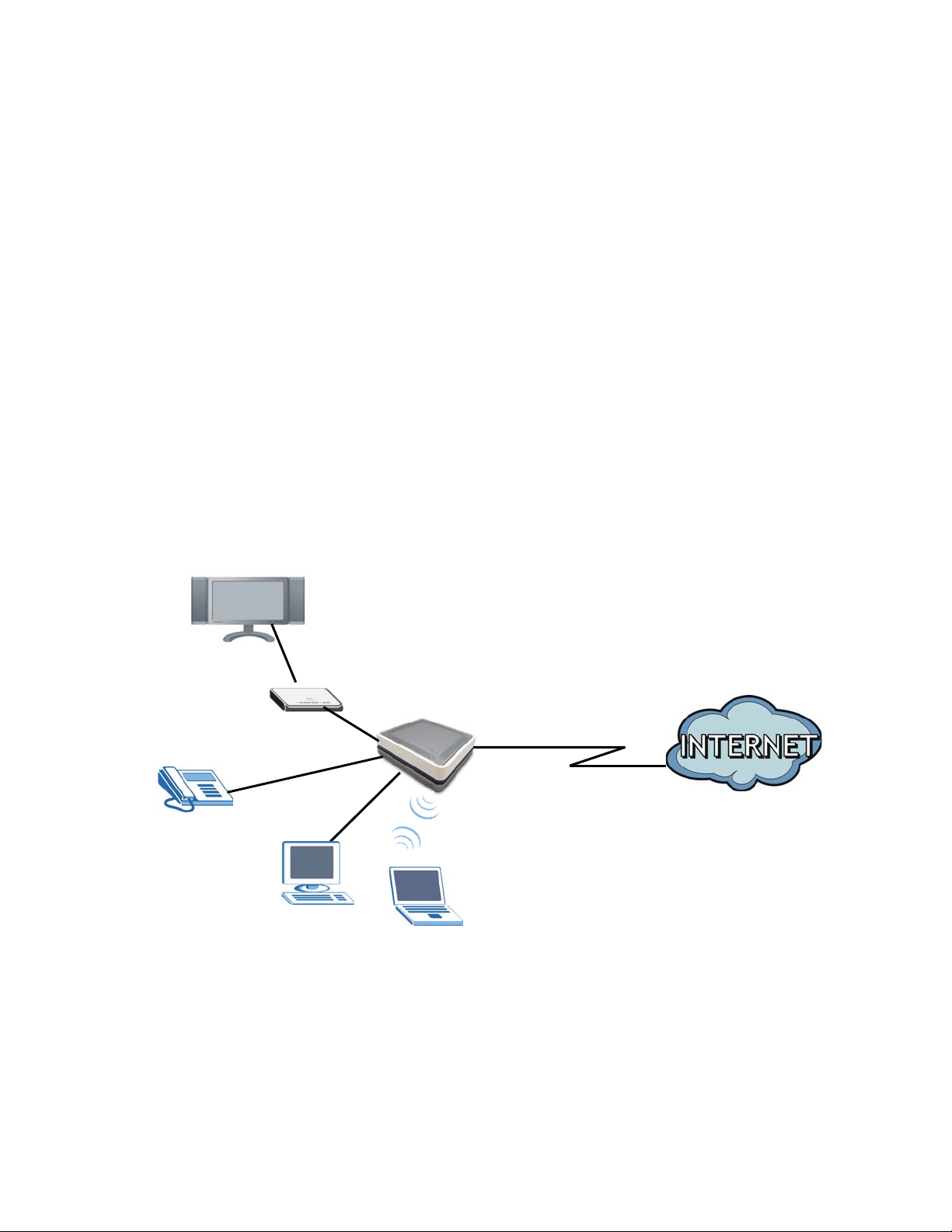
1.2 Hardware Connection
Make sure to use the proper cables and power adapter to connect the Router.
Figure 2 Rear Panel
The following table explains the connectors and buttons on the rear panel.
Table 1 Rear Panel
CONECTOR DESCRIPTION
12V-2A Connect the provided power adapter to the 12V-1A power connector. Attach the
power adapter to a proper power source.
ON/OFF Use this button to turn the Router on or off.
Fibra Óptica Connect the service provider’s fiber optic cable to this port.
Telf Use a telephone cable to connect the Router to a VoIP phone for VoIP service.
Eth 1-4 Use an Ethernet cable to connect a computer to one of these ports for initial
configuration and/or Internet access.
Wifi/WPS Use this button to enable or disable the 2.4 GHz WiFi and WPS features on the Router.
By default, WiFi is enabled on the Router. Press this button for 1 second to turn it off.
To enable the WPS feature, press the button for more than 3 seconds The WPS LED on
the front panel will flash green while the Router sets up a WPS Connection with the
wireless device.
Note: To activate WPS, you must enable WPS in the Router and in another wireless
device within two minutes of each other.
Chapter 1 Introduction 10
Wifi5GHz/WPS Use this button to enable or disable the 5 GHz WiFi and WPS features on the Router.
By default, WiFi is enabled on the Router. Press this button for 1 second to turn it off.
To enable the WPS feature, press the button for more than 3 seconds The WPS LED on
the front panel will flash green while the Router sets up a WPS Connection with the
wireless device.
Note: To activate WPS, you must enable WPS in the Router and in another wireless
device within two minutes of each other.
Reset Use this button to restore the default settings of the Router. Press this button for 10
seconds to restore default values. Press 1 second or longer to restart it.
Note: If you reset the Router, you will lose all configurations that you had previously
and the password will be reset to the defaults.
Table 1 Rear Panel (continued)
CONECTOR DESCRIPTION
Chapter 1 Introduction 11
1.3 LEDs (Lights)
The following graphic displays the labels of the LEDs.
Figure 3 Front Panel LEDs
Figure 4 Rear Panel LEDs
Table 2 LED Descriptions
LED COLOR STATUS DESCRIPTION
Power Blue On The Router is receiving power and ready for use.
Red On The Router has hardware failure.
Blinking The Router detected an error while self-testing.
Off The Router is not receiving power.
Eth 1-4 Blue On The Router has a successful Ethernet connection with a device on
the LAN.
Blinking The Router is sending or receiving data to/from the LAN.
Off The Router does not have an Ethernet connection with the LAN.
Chapter 1 Introduction 12
1.4 Advanced Configuration
Do the following to access the advanced configuration screens.
Telf Blue On The SIP registration is successful.
Blinking The Router is negotiating the SIP registration.
Green On There is incoming or outgoing voice traffic.
Red Blinking The Router has failed to register the VoIP service.
Off There is no VoIP service.
Wifi/WPS Blue On The 2.4 GHz wireless is on.
Blinking The 2.4 GHz WPS is activated. It also blinks when the Router is
setting up a WPS connection.
Off The 2.4 GHz wireless is not activated.
Wifi5GHz/
WPS
Blue On The 5 GHz wireless is on.
Blinking The 5 GHz WPS is activated. It also blinks when the Router is setting
up a WPS connection.
Off The 5 GHz wireless is not activated.
Internet Blue On The Router has a PPP connection but no traffic.
It has a WAN IP address (either static or assigned by a DHCP server),
PPP negotiation was successfully completed (if used).
Blinking Startup process. The Router is running an automatic startup
diagnostic process on the GPON port.
Fast Blinking The Router is sending or receiving IP traffic.
The Router is synchronizing with the PON. Activation phase. The
Router is negotiating a PPP connection.
Red On The Router attempted to make an IP connection but failed. Possible
causes are no response from a DHCP server, no PPPoE response,
PPPoE authentication failed.
The GPON port failed during the POST (Power On Self Test) or there
is an error due to hardware or firmware failure.
Blinking The GPON port’s optical power level is below the threshold.
Off There is no Internet connection.
Table 2 LED Descriptions (continued)
LED COLOR STATUS DESCRIPTION
Chapter 1 Introduction 13
1Access the Client Wizard screens. Enter the IP address: http://192.168.1.1.
2The login screen appears. The default password is random. Please refer to the label sticker at the
bottom of the device. Enter the password. Click Entrar to enter the Client Wizard.
3The main screen appears.
Chapter 1 Introduction 14
4Click the Menu button and then Configuración avanzada.
5Click Aceptar.
Chapter 1 Introduction 15
6The advanced configuration screens display. Use the menu on the left to navigate the screens. Refer
to the rest of this guide for details about the screens. Click Logout to exit the configuration screens.
2
Chapter
Chapter 2 Device Info 16
CHAPTER 2
Chapter 2 Device Info
2.1 Device Info Summary
Click Device Info > Summary to open this screen with general device and WAN connection status
information.
Figure 5 Device Info Summary
Table 3 Device Info Summary
LABEL DESCRIPTION
Board ID This field displays the ID number of the circuit board in the Router.
Symmetric
CPU Threads
This field displays the number of threads in the Router’s CPU.
Build
Timestamp
This field displays the date (YYMMDD) and time (HHMM) of the firmware in the Router.
Software
Version
This field displays the current version of the firmware inside the Router.
Chapter 2 Device Info 17
Bootloader
(CFE) Version
This field displays the version of bootloader the Router is using.
Wireless
Driver Version
This field displays the version of the driver for the Router’s wireless chipset.
Voice Service
Version
This field displays the version of the VoIP software the Router is using.
Uptime This field displays how long the Router has been running since it last started up.
LAN IPv4
Address
This field displays the current IP address of the Router in the LAN.
Default
Gateway
This field displays the IP address of the gateway through which the Router sends traffic
unless it matches a static route.
Primary DNS
Server
The Router tries this DNS server first when it needs to resolve a domain name into a
numeric IP address.
Secondary
DNS Server
The Router uses this DNS server first when it needs to resolve a domain name into a
numeric IP address if the primary DNS server does not respond.
LAN IPv6 ULA
Address
This field displays the current unique local address (ULA). This is a unique IPv6 address
for use in private networks but not routable in the global IPv6 Internet.
LAN IPv6
Address
(Global)
This field displays the current global IPv6 address of the Router.
LAN IPv6 Link
Local Address
This field displays the current IPv6 address of the Router in the LAN.
Default IPv6
Gateway
This field displays the IPv6 address of the gateway through which the Router sends IPv6
traffic unless it matches a static route.
Date/Time This field displays the Router’s current day of the week, month, hour, minute, second,
and year.
Table 3 Device Info Summary (continued)
LABEL DESCRIPTION
Chapter 2 Device Info 18
2.2 WAN Info
Click Device Info > WAN to open this screen which lists the Router’s WAN connections and their
status.
Figure 6 WAN Info
Table 4 WAN Info
LABEL DESCRIPTION
Interface This shows the name of the WAN interface. veip0 stands for a virtual Ethernet card and
is the foundation for veip0/* which are virtual WAN interfaces of the physical GPON line.
The ppp0.* indicates a PPP connection.
The number after the dot (.) represents the VLAN ID number assigned to traffic sent
through this connection. The number after the underscore (_) represents the index
number of connections through the same interface.
(null) means the entry is not valid.
Description This is the service name of this connection.
Type This shows the method of encapsulation used by this connection (IP over Ethernet, PPP
over Ethernet, or bridging).
VlanMuxID This indicates the VLAN ID number assigned to traffic sent through this connection. This
displays N/A when there is no VLAN ID number assigned.
IPv6 This displays whether or not IPv6 is enabled on the interface.
Igmp Pxy This shows whether IGMP (Internet Group Multicast Protocol) proxy is activated or not
for this connection. IGMP is not available when the connection uses the bridging service.
Igmp Src Enbl This shows whether IGMP source enable is activated or not for this connection. IGMP
source enable has the Router add routing table entries based on the IGMP traffic.
MLD Pxy This shows whether Multicast Listener Discovery (MLD) proxy is activated or not for this
connection. MLD is not available when the connection uses the bridging service.
MLD Src Enbl This shows whether MLD source enable is activated or not for this connection. MLD
source enable has the Router add routing table entries based on the MLD traffic.
NAT This shows whether NAT is activated or not for this interface. NAT is not available when
the connection uses the bridging service.
Status This displays the connection state or Unconfigured if the interface has not yet been
configured.
Chapter 2 Device Info 19
2.3 LAN Statistics
Click Device Info > Statistics > LAN to open this screen of traffic statistics counters for the Router’s
wired and wireless LAN interfaces. Use the button to clear the counters.
Figure 7 LAN Statistics
IPv4 Address This displays the interface’s current IPv4 address if it has one.
IPv6 Address This displays the interface’s current IPv6 address if it has one.
Table 4 WAN Info (continued)
LABEL DESCRIPTION
Table 5 LAN Statistics
LABEL DESCRIPTION
Interface These fields identify the LAN interfaces. eth0~ eth3 represent the ethernet LAN ports 1
~ 4. wlo represents the wireless LAN interface.
Received /
Transmitted
These fields display the number of bytes, packets, error packets, and dropped packets
for each interface.
Received
Bytes This indicates the number of bytes received on this interface.
Pkts This indicates the number of packets received on this interface.
Errs This indicates the number of frames with errors received on this interface.
Drops This indicates the number of received packets dropped on this interface.
Transmitted
Bytes This indicates the number of bytes transmitted on this interface.
Chapter 2 Device Info 20
Pkts This indicates the number of transmitted packets on this interface.
Errs This indicates the number of frames with errors transmitted on this interface.
Drops This indicates the number of outgoing packets dropped on this interface.
Reset
Statistics
Click this to clear the screen’s statistics counters.
Table 5 LAN Statistics (continued)
LABEL DESCRIPTION

Other MitraStar Network Router manuals

MitraStar HGW-2501GN-R2 User manual

MitraStar

MitraStar HGW-2501GN-R2 User manual

MitraStar DSL-2401HNA-T1CC User manual

MitraStar

MitraStar DSL-2401HNA-T1CC User manual

Popular Network Router manuals by other brands

Edimax Wireless VPN Broadband Router user manual

Edimax

Edimax Wireless VPN Broadband Router user manual

Allied Telesis AT-9724TS Installation and user guide

Allied Telesis

Allied Telesis AT-9724TS Installation and user guide

Acromag EIS-358 user manual

Acromag

Acromag EIS-358 user manual

Huawei S6700 Series Hardware description

Huawei

Huawei S6700 Series Hardware description

Huawei E5785-320a quick start

Huawei

Huawei E5785-320a quick start

Deltenna WiBE HS21 quick start guide

Deltenna

Deltenna WiBE HS21 quick start guide

Advantech SmartStart SL302 user manual

Advantech

Advantech SmartStart SL302 user manual

Draytek Vigor2865ac-B quick start guide

Draytek

Draytek Vigor2865ac-B quick start guide

NETGEAR RT338 reference guide

NETGEAR

NETGEAR RT338 reference guide

D-Link DMC-300SC - Media Converter - External Quick installation guide

D-Link

D-Link DMC-300SC - Media Converter - External Quick installation guide

Planet XRT-401B user guide

Planet

Planet XRT-401B user guide

TP-Link AC1900 Specifications

TP-Link

TP-Link AC1900 Specifications

Siemens SIMATIC ET 200SP operating instructions

Siemens

Siemens SIMATIC ET 200SP operating instructions

ZyXEL Communications UAG5100 Firmware release notes

ZyXEL Communications

ZyXEL Communications UAG5100 Firmware release notes

TP-Link TL-WR902AC user guide

TP-Link

TP-Link TL-WR902AC user guide

ZyXEL Communications NBG6816 user guide

ZyXEL Communications

ZyXEL Communications NBG6816 user guide

NETGEAR Home Router Setup guide

NETGEAR

NETGEAR Home Router Setup guide

TP-Link Archer AXE200 Omni V1 user guide

TP-Link

TP-Link Archer AXE200 Omni V1 user guide

manuals.online logo
manuals.online logoBrands
  • About & Mission
  • Contact us
  • Privacy Policy
  • Terms and Conditions

Copyright 2025 Manuals.Online. All Rights Reserved.