MitraStar HGW-2501GN-R2 User manual

Edition 1, 8/2014
HGW-2501GN-R2
User’s Guide

IMPORTANT!
READ CAREFULLY BEFORE USE.
KEEP THIS GUIDE FOR FUTURE REFERENCE.
Graphics in this book may differ slightly from the product due to differences in operating systems,
operating system versions, or if you installed updated firmware/software for your device. Every
effort has been made to ensure that the information in this manual is accurate.

Contents 3
Contents
8 Chapter 1: Introducción
8Overview
9 Hardware Connection
10 LEDs (Lights)
12 Chapter 2: The Installation Wizard
12 Overview
12 Access the Router
14 Changing the Password
15 Tu Router
16 Configuración Básica
16 IPTV Configuration
19 VoIP Configuration
20 Configuración Avanzada
22 The Web Configurator Layout
22 Title Bar
23 Main Window
24 Chapter 3: The Client Wizard
24 Access the Router
25 Configuración Básica
25 Wireless Configuration
27 IPv4 NAT Port Forwarding Configuration
28 IPv6 Firewall Configuration
30 Connection Line Configuration
31 LAN Configuration
33 Profile Configuration
34 Firmware Upgrade
36 Chapter 4: Quick Start
36 Overview
36 Quick Start Setup
38 Chapter 5: Connection Status and System Info
38 The Connection Status Screen
39 The System Info Screen

Contents 4
40 Chapter 6: WAN
40 The WAN Screen
41 Edit Ethernet Connection
44 Chapter 7: Wireless 2.4GHz
44 Wireless General Screen
46 No Security
47 Basic (WEP Encryption)
48 More Secure (WPA(2))
49 More Secure (WPA(2)-PSK)
50 More AP Screen
51 Edit More AP
52 MAC Authentication Screen
53 The WPS Screen
55 The WDS Screen
56 The WMM Screen
57 Scheduling Screen
58 Add or Edit Schedule
59 Advanced Screen
60 Chapter 8: LAN
60 The LAN Setup Screen
62 The Static DHCP Screen
63 The IP Alias Screen
64 The UPnP Screen
65 The IPv6 LAN Setup Screen
69 Chapter 9: Static Route
69 Configuring Static Route
70 Add/Edit Static Route
70 IPv6 Static Route
71 Add/Edit IPv6 Static Route
72 The DNS Route Screen
72 Add/Edit DNS Route
73 The Current Route Screen
74 Chapter 10: DNS Route
74 Overview
74 The DNS Route Screen
75 Add/Edit DNS Route
76 Chapter 11: Quality of Service (QoS)
76 The QoS General Screen

Contents 5
77 The Queue Setup Screen
78 Edit a QoS Queue
78 The Class Setup Screen
80 Add/Edit QoS Class
84 The QoS Monitor Screen
85 Chapter 12: Network Address Translation (NAT)
85 The General Screen
85 The Port Forwarding Screen
86 The Port Forwarding Screen
87 The Port Forwarding Add/Edit Screen
88 The Address Mapping Screen
89 The Address Mapping Rule Edit Screen
90 The DMZ Screen
90 The ALG Screen
92 Chapter 13: Dynamic DNS
92 The Dynamic DNS Screen
94 Chapter 14: Filter
94 The IP/MAC Filter Screen
96 The IPv6/MAC Filter Screen
98 Chapter 15: Firewall
98 TFirewall General Screen
99 Add/Edit Interface Default Policy Screen
99 Rules Screen
101 Rules Edit Screen
102 DoS Screen
103 The DoS Advanced Screen
104 Chapter 16: Parental Control
104 The Parental Control Screen
106 Add/Edit a Parental Control Rule
108 Chapter 17: Certificates
108 Local Certificates
109 Trusted CA
110 Trusted CA Import
111 View Certificate
112 Chapter 18: VoIP
112 The SIP Account Screen

Contents 6
113 Edit SIP Account
116 The SIP Service Provider Screen
117 Edit SIP Service Provider
122 Phone Screen
123 Call Rule Screen
124 Chapter 19: System Monitor
124 The Log Screen
125 The WAN Traffic Status Screen
126 The LAN Traffic Status Screen
127 The NAT Traffic Status Screen
128 The VoIP Status Screen
130 Chapter 20: User Account
130 Overview
130 The User Account Screen
131 Chapter 21: TR-069 Client
131 The TR-069 Screen
133 Chapter 22: System
133 The System Screen
134 Chapter 23: Time Setting
134 The Time Setting Screen
136 Chapter 24: Log Setting
136 The Log Setting Screen
139 Chapter 25: Firmware Upgrade
139 The Firmware Upgrade Screen
141 Chapter 26: Backup/Restore
141 The Backup/Restore Screen
143 The Reboot Screen
144 Chapter 27: Remote Management
144 The General Screen
144 The WWW Screen
146 Telnet Screen
146 FTP Screen
148 SNMP Screen
149 DNS Screen
150 ICMP Screen

1
Chapter
Chapter 1 Introducción 8
CHAPTER 1
Chapter 1 Introducción
1.1 Overview
The HGW-2501GN-R2 combines a router which combines high-speed Internet access, a built-in
switch, a firewall and high-speed wireless networking capability. It has one phone port for making
calls over the Internet (Voice over IP or VoIP). In addition, it supports IPTV service if it is available
from your service provider.
The following figure shows an application example of the Router:
The Router is connected to a GPON ONT and provides IPTV, VoIP services as well as wired and
wireless Internet access to home devices on the LAN.
Figure 1 Application Example
HGW-2501GN-R2
ONT
Set-Top Box
VoIP Phone

Chapter 1 Introducción 9
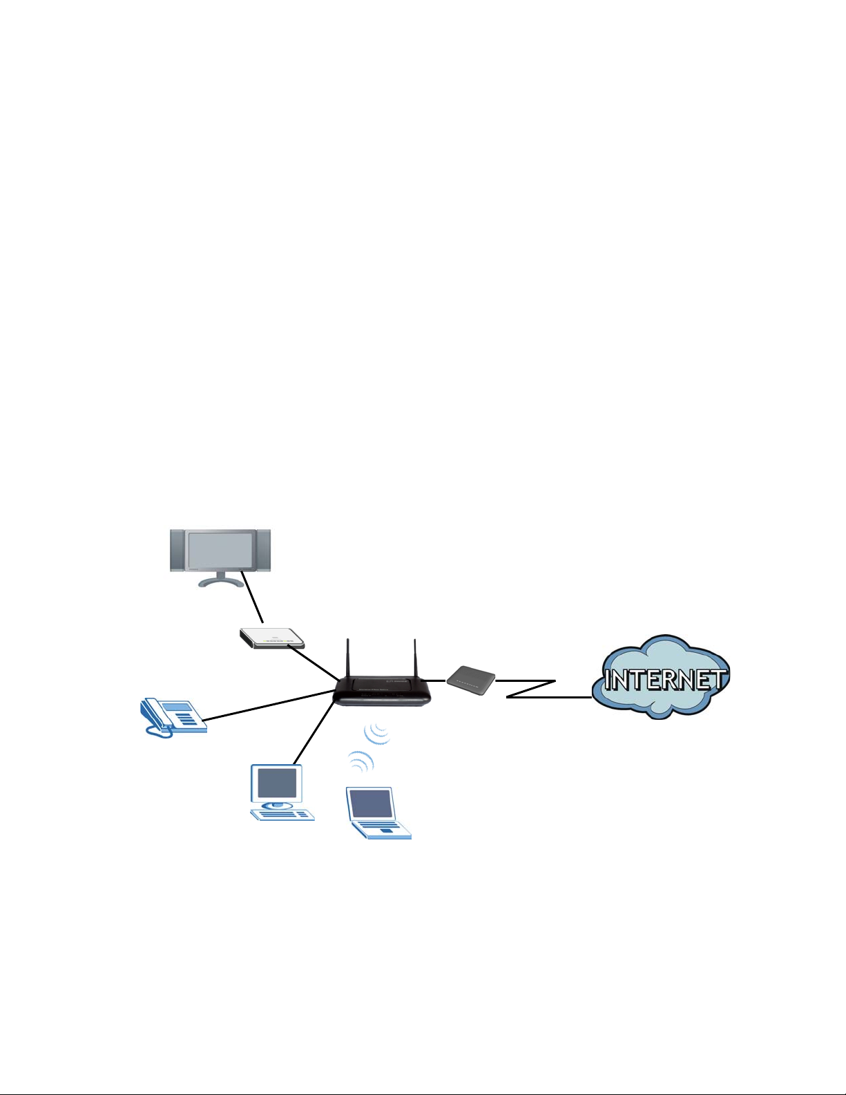
1.2 Hardware Connection
Make sure to use the proper cables and power adapter to connect the Router.
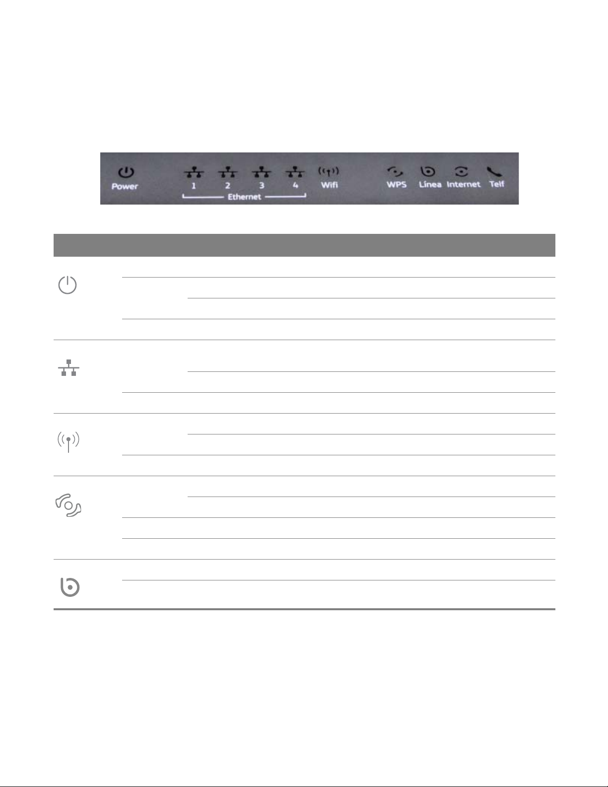
Figure 2 The Rear Panel
La descripción de los conectores y botones anteriormente visualizados se muestra en la siguiente
tabla:
Table 1 The Rear Panel
CONECTOR DESCRIPTION
ON/OFF Use this button to turn the Router on or off.
12V-1A Connect the provided power adapter to the 12V-1A power connector. Attach the
power adapter to a proper power source.
Eth 1-4 Use an Ethernet cable to connect a computer to one of these ports for initial
configuration and/or Internet access.
Internet This is the Router’s WAN interface. Use an RJ-45 cable to connect the Router to an ONT.
Telf1 Use a telephone cable to connect the Router to a VoIP phone for VoIP service.
Reset Use this button to restore the default settings of the Router. Press this button for 10
seconds to restore default values. Press 1 second or longer to restart it.
Note: If you reset the Router, you will lose all configurations that you had previously
and the password will be reset to the defaults.
Wifi/WPS Use this button to enable or disable the WiFi and WPS features on the Router.
By default, WiFi is enabled on the Router. If you want to turn it off, press this button
for 1 second to turn it off.
To enable the WPS feautre, press the button for more than 3 seconds The WPS LED on
the front panel will flash green while the Router sets up a WPS Connection with the
wireless device.
Note: To activate WPS, you must enable WPS in the Router and in another wireless
device within two minutes of each other.

Chapter 1 Introducción 10
1.3 LEDs (Lights)
The following graphic displays the labels of the LEDs.
Figure 3 Front Panel LEDs
Table 2 LED Descriptions
LED COLOR STATUS DESCRIPTION
Power Green On The Router is receiving power and ready for use.
Red On The Router has hardware failure.
Blinking The Router detected an error while self-testing.
Off The Router is not receiving power.
Ethernet 1-4 Green On The Router has a successful Ethernet connection with a device on
the LAN.
Blinking The Router is sending or receiving data to/from the LAN.
Off The Router does not have an Ethernet connection with the LAN.
Wifi Green On The wireless network is activated.
Blinking The Router is communicating with other wireless clients.
Off The wireless network is not activated.
WPS Green On The WPS is activated but there is no WPS connection.
Blinking The Router is setting up a WPS connection.
Red On There is a problem with the WPS connection.
Off The WPS is not activated.
Línea Green On The Router is connected and synchronized with an ONT.
Off The Router is off line or not connectede to an ONT.

Chapter 1 Introducción 11
Internet Green On The Router has an IP connection but no traffic.
It has a WAN IP address (either static or assigned by a DHCP server),
PPP negotiation was successfully completed (if used).
Blinking The Router is negotiating a PPP connection.
Fast Blinking The Router is sending or receiving IP traffic.
Red On The Router attempted to make an IP connection but failed. Possible
causes are no response from a DHCP server, no PPPoE response,
PPPoE authentication failed.
Off There is no Internet connection.
Telf Green On The SIP registration is successful.
Blinking The Router is negotiating the SIP registration.
Fast Blinking There is incoming/outgoing voice traffic.
Red On The Router has failed to register the VoIP service. There is problem
with the SIP account.
Off There is no VoIP service.
Table 2 LED Descriptions (continued)
LED COLOR STATUS DESCRIPTION

2
Chapter
Chapter 2 The Installation Wizard 12
CHAPTER 2
Chapter 2The Installation Wizard
2.1 Overview
The web configurator HTML-based management interface allows easy device setup and
management via Internet browser. Use Internet Explorer 6.0 and later versions, Mozilla Firefox 3
and later versions, or Safari 2.0 and later versions. The recommended screen resolution is 1024 by
768 pixels.
In order to use the web configurator you need to allow:
• Web browser pop-up windows from your device. Web pop-up blocking is enabled by default in
Windows XP SP (Service Pack) 2.
• JavaScript (enabled by default).
• Java permissions (enabled by default).
2.2 Access the Router
The Installation Wizard helps you to configure the services you want to use on the Router.
Connect to the Web Configurator to access the Installation Wizard screens. Enter the IP address:
http://192.168.1.1/instalacion.

Chapter 2 The Installation Wizard 13
The login screen appears. The default password is 1234. Enter the password. Click Iniciar to enter
the Installation Wizard.
The main screen appears. Click the buttons in this screen for basic or advanced configurations of
the Router.
123
4
5
6
1Español / English - change the language.
2Cambiar contraseña - change the configuration password (see Section 2.3 on page 14).

Chapter 2 The Installation Wizard 14
3Consejos - display tips and frequently asked questions.
4Tu Router - display basic information of the Router (see Section 2.4 on page 15).
5Configuración Básica - select the services you want to use and configure related settings (see
Section 2.5 on page 16).
6Configuración Avanzada - access and configure settings for all the features of the Router (see
Section 2.6 on page 20).
2.3 Changing the Password
1Click the main screen’s Cambiar contraseña link (1in the figure).
2Enter the Router’s current password in the Contraseña actual field.
3Enter the new password in the Nueva contraseña field. You can check the strength of the new
password in the Fortaleza de la contraseña indicator.
4Retype the new password in the Repetir nueva contraseña field and click Aplicar to save the
setting and exit this screen.
1
2
3
4

Chapter 2 The Installation Wizard 15
2.4 Tu Router
Mouse-over the Tu Router button to show basic information of the Router. You can see the
manufacturer company name, model name, current firmware version, and whether the Router is
connected to the Internet.

Chapter 2 The Installation Wizard 16
2.5 Configuración Básica
In the Configuración Básica section of the wizard, you can set the services you want to use on the
Router. Make sure the services are provided by your service provider. Click the Configuración
Básica button to show the following screen.
1In the Tipo de Servicio Contratado section, if your service provider provides IPTV service, select
TRIO. If not, select DUO:
•DUO: Internet and VoIP service
•TRIO: Internet, VoIP, and IPTV service
2If VoIP service is available, select SI from the Tu linea de Voz section. Otherwise, select NO.
3Click Asistente de Instalación to go to the next screen.
2.5.1 IPTV Configuration
The screens in this section are available only when TRIO is selected in the previous screen.
The way your set-top box obtains its IP address depends on the service provider.

Chapter 2 The Installation Wizard 17
A. If your service provider provides an IP for the set-top box, select Estático.
1Click Asistente de Instalación to show the following screen.
2The NAT feature is disabled and you need to enter the router’s LAN IP address in Dirección IP
(LOCAL). Enter the IPTV (set-top box)’s IP address (from the service provider) in Dirección IP TV and
subnet mask in Máscara de subred.
3Click Siguiente to go to the next screen.

Chapter 2 The Installation Wizard 18
B. If your service provider did not provide an IP for the set-top box, select Dinámico NatPat to
enable the NAT feature, so the set-top box obtains its IP address automatically from the service
provider.
1Click Asistente de Instalación to show the following screen.
2The IPTV (set-top box)’s IP address and subnet mask are already configured. If no change is
required, click Siguiente to go to the next screen.

Chapter 2 The Installation Wizard 19
2.5.2 VoIP Configuration
This screen is available only when If you selected SI from the Tu linea de Voz section in the
Configuración Básica screen.
1You need to enter your SIP account number (provided by your service provider) in the following
screen.
2Click Siguiente to go to the next screen.
3Asummary of your settings will appear. Click Aplicar to continue.

Chapter 2 The Installation Wizard 20
4If you need to configure other settings such as the the Router’s LAN and wireless features, click on
the IP address shown in the following screen to go to the Client Wizard screens. If not, click Salir to
finish.
2.6 Configuración Avanzada
In the Configuración Avanzada section of the wizard, you can access all of the configuration
screens of the Router which can be used for advanced setup. Find detailed information on each
configuration screen, starting from Chapter 5 on page 38.
1Click the Configuración Avanzada button.
2Click Aceptar after reading the following notice.
Table of contents
Other MitraStar Network Router manuals