manuals.online logo
Brands
  1. Home
  2. •
  3. Brands
  4. •
  5. Mitre10
  6. •
  7. Indoor Furnishing
  8. •
  9. Mitre10 BD60D2P-IMP User manual

Mitre10 BD60D2P-IMP User manual

This manual suits for next models

2

Other Mitre10 Indoor Furnishing manuals

Mitre10 PANTRY CABINET TALL RETURN PR1000-IMP User manual

Mitre10

Mitre10 PANTRY CABINET TALL RETURN PR1000-IMP User manual

Popular Indoor Furnishing manuals by other brands

Regency LWMS3015 Assembly instructions

Regency

Regency LWMS3015 Assembly instructions

Furniture of America CM7751C Assembly instructions

Furniture of America

Furniture of America CM7751C Assembly instructions

Safavieh Furniture Estella CNS5731 manual

Safavieh Furniture

Safavieh Furniture Estella CNS5731 manual

PLACES OF STYLE Ovalfuss Assembly instruction

PLACES OF STYLE

PLACES OF STYLE Ovalfuss Assembly instruction

Trasman 1138 Bo1 Assembly manual

Trasman

Trasman 1138 Bo1 Assembly manual

Costway JV10856 manual

Costway

Costway JV10856 manual

moss DESIGN Caisson Credenza Assembly instructions

moss DESIGN

moss DESIGN Caisson Credenza Assembly instructions

Aquaglide FULL DECK 15.0 owner's manual

Aquaglide

Aquaglide FULL DECK 15.0 owner's manual

AREBOS AR-HE-SW30 user manual

AREBOS

AREBOS AR-HE-SW30 user manual

Till-Hilft Fulda 87005.330 Assembly instructions

Till-Hilft

Till-Hilft Fulda 87005.330 Assembly instructions

Twoey Outside 2010 quick start guide

Twoey Outside

Twoey Outside 2010 quick start guide

Hettich Easys 200 operating instructions

Hettich

Hettich Easys 200 operating instructions

The bedboss RELAX 404 Series owner's manual

The bedboss

The bedboss RELAX 404 Series owner's manual

Oeseder Möbelindustrie Bern 991 720 Assembly instructions

Oeseder Möbelindustrie

Oeseder Möbelindustrie Bern 991 720 Assembly instructions

Costway HW68469 user manual

Costway

Costway HW68469 user manual

Next ALIX A27743 Assembly instructions

Next

Next ALIX A27743 Assembly instructions

BROSA Hans Assembly guide

BROSA

BROSA Hans Assembly guide

Prodigg MINIKA PBA015T-FUR installation manual

Prodigg

Prodigg MINIKA PBA015T-FUR installation manual

manuals.online logo
manuals.online logoBrands
  • About & Mission
  • Contact us
  • Privacy Policy
  • Terms and Conditions

Copyright 2025 Manuals.Online. All Rights Reserved.

Cabinet
Panels
included.
Hardware
included.
Required
Tools.
Handy
Tools.
Manufactured in New Zealand for: Mitre 10 New Zealand Limited.
Bottom Panel x1
10.5mm Drawer
Screw ( 24 )
Back Panel x1 Side Panels x2 Rail Panel x1 Drawer Base Panel x3
SCREWS
POWER DRILL
CLAMP LEVEL TAPE
MEASURE
PENCIL LADDER
DOWELS ( 16 )
LEG BASES ( 4 )
ADJ. LEGS ( 4 )
KICK CLIP ( 2 ) DRAWER BACKS ( 3 )
GALLERY RAIL SETS ( 2 )
DRAWER
SETS ( 3 )
FOOT
( 4 )
CONNECTOR
SCREWS ( 2 )
PZ2 BIT 5MM
DRILL BIT
RUBBER
MALLET
SCREWDRIVER
Installing Leg Bases.
Fixing Bottom and Back Panel.
Inserting Dowels
into Side Panels
1.
2.
3.
Note: Position leg base as shown
in the image to support side panel.
• Fix the Leg bases by aligning them on the base panel as shown.
• Ensure dowels in the leg bases line up with the holes. Use a block of wood
between leg base and mallet to prevent damage before striking it into place.
• Lay the back down at as shown.
• Use 50mm Cabinet Screws to x the bottom panel to the back panel.
• While laying the panels at, insert
the dowels into the correct holes as
marked in the image shown.
BASE CABINET
3 DRAWER UNIT
Assembly Instructions
Suitable for Base Cabinet
BD60D2P-IMP, BD80D2P-IMP,
BD90D2P-IMP
732.25.817
50mm Cabinet
screw A ( 15 ), B ( 16 )
15mm Cabinet
screw ( 36 )
29mm counter sunk
screw ( 2 )
TOP FIXING
BRACKET ( 2 )
Handy Note: Please read the instructions carefully before you start and make sure to identify the parts you need for each step.
When assembling it is best to do on a soft surface to prevent damage.
Note: Connector screws are
used to connect two carcase
units together. 5mm through
holes are provided on some
of the front edges of the side
panels to connect adjacent
carcase.
Legend
A. = BD60D2P-IMP
B. = BD80D2P-IMP
BD90D2P-IMP
( 4 ) 16mm Drawer
Front Screw
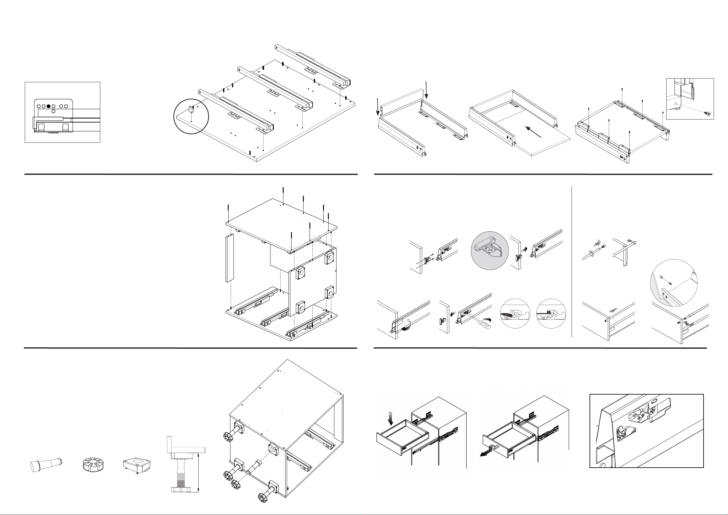
Fixing The Runners to Side Panels.
Fixing Side Panels to Back and Base.
4.
5.
• Fix the runners onto the side panels with the supplied Drawer Screws.
• The third hole on the runner should line up with the rst hole on the side
panels as shown in the image below.
• Align the base and back panel onto the dowels on the side panel.
• Align the rail onto the correct dowels as shown in the image.
• Lift and align the second side panel to ensure dowels are aligned
with the corresponding holes. Use 50mm Cabinet Screws to x the
rail, back and bottom to the side panel.
• Flip the cabinet to secure the other side panel with back, base
and rail panel using 50mm Cabinet Screws.
Fixing leg and foot to leg base.
6.
• Cabinet Feet: Push the supplied adjustable leg into the foot
and then insert it into the leg base attached to the base panel.
• Height of the Adj Legs = ±150mm
• Height of the Cabinet = 720mm
• Height of Cabinet + Adj Legs = 870mm
Note: Max. Height of end panels is 870mm.
150mm
+ +
ADJUSTABLE LEGS FOOT LEG BASE
Runner Detail
• Note: 1 x 15mm Cabinet screw used
per bracket to x benchtop to the cabinet.
=
Drawer Installation & adjustments.
8.
9.
a. Installing the drawer fronts. b. Installing the Gallery Rails.
3. To remove the front, remove the cap and undo the clip using a screwdriver.
1. Clip the gallery rail
to the back panel.
• Slide out the slides, and place the
drawer in from above onto slides.
• Lift the drawer up to dismantle • (a) Use to adjust drawer front left or right.
• (b) Use to adjust drawer front up and down.
3. Slide plastic cover
over front connector.
(a)
(b)
Drawer Clip
OPEN CLOSED
Assembling the drawers.
7.
• Slide the back into the drawer sides until
you hear a click sound as shown in the
image. (Large backs are for pot drawers).
• Slide the drawer base into place as
shown in the image below.
1. Using a screw drive, t the drawer
front mounting clips onto the drawer
front, using the 16mm drawer front
screws on the prick marks on the front
as your guide
2. Clip drawer front into the slots
of the side until it locks in.
2. On selected drawer fronts,
use the prick marks above the
drawer clip, and screw the
gallery rail connector to the
drawer front with the 15mm
screws. Then clip the gallery
rail on.
• Flip the drawer unit as below, and screw
drawer sides to the base using 15mm screws.
Finish by securing back into drawer base using
15mm screws.