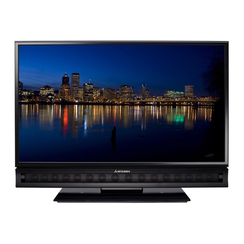
Mitsubishi Electric Unisen LT-55154 User manual

Version 13.0 05/05/2011
MITSUBISHI DIGITAL ELECTRONICS AMERICA, INC.
9351 Jeronimo Road, Irvine, CA 92618-1904
Copyright © 2010 Mitsubishi Digital Electronics America, Inc.
All Rights Reserved
CAUTION:
Before servicing this chassis, it is important that the service person read the "SAFETY PRECAUTIONS" and
"PRODUCT SAFETY NOTICE" contained in this manual.
LCD FLAT PANEL HDTV
VLP43 Chassis
LT-55154
VLP43+ Chassis
LT-40164
LT-46164
LT-55164
SPECIFICATIONS
• Power Input : AC 120V, 60Hz
• LCD Panel : Resolution - 1920 x 1080
: Refresh Rate -
120 Hz (VLP43, VLP43+)
240 Hz (VLP43++)
• Tuning : NTSC/ATSC/QAM
: Analog Cable - 1~125
Digital Cable - 1~135
•Antenna Input : RF 75 Ohms unbalanced
• Speakers : 2W x 12 (VLP43)
: 2W x 16 (VLP43+)
: 2W x 16 & 20W x 2 (VLP43++)
• See Page 5 for additional specifications.
• Design specifications are subject to change without notice.
Manual
Service
VLP43++ Chassis
LT-46265
LT-55265
• Analog Input : VIDEO IN JACK (RCA Type)
Level Y/Video - 1.0Vp-p, Cr, Cb - 700mVp-p
75unbalanced
: AUDIO / CENTER CHANNEL IN JACK
(RCA Type)
-4.7dBm 43kunbalanced
• Analog Output : AUDIO / SUBWOOFER OUT JACK
Level (RCA Type)
-4.7dBm 4.7kunbalanced
• Digital : HDMI™ 1.3 Inputs
Inputs/Outputs : Digital Audio Output (RCA)(AC-3, PCM)
: USB Input
: Wired IR Input/Output (VLP43++)
: WiFi (VLP43+, VLP43++)
: Ethernet
: Bluetooth (VLP43+, VLP43++)
2010


Page 3
MODELS: LT-55154 / LT-40164 / LT-46164 / LT-55164 / LT-46265 / LT-55265
CONTENTS
INTRODUCTION..................................................................................................................................5
Dimensions, Weight, etc...................................................................................................................5
PRODUCT SAFETY NOTICE..............................................................................................................5
SAFETY PRECAUTIONS....................................................................................................................6
DISASSEMBLY & PARTS REPLACEMENT......................................................................................7
Back Cover Removal........................................................................................................................7
Panel Holder Removal......................................................................................................................7
Stand Removal.................................................................................................................................8
Major Component Locations.............................................................................................................9
LCD Panel Removal.........................................................................................................................9
Assembly–Speaker-Box Removal..................................................................................................10
Assembly–Speaker-Box Disassembly............................................................................................10
PWB-CONTROL Removal .............................................................................................................11
PWB-FILTER Removal...................................................................................................................11
PWB-POWER Removal .................................................................................................................12
WLAN-MODULE Removal .............................................................................................................12
PWB-MAIN (Assembly) Removal...................................................................................................12
PWB-MAIN Removal......................................................................................................................13
Wiring and Wire Clamp Locations..................................................................................................14
SERVICE PROCEDURES .................................................................................................................15
Remote Control ..............................................................................................................................15
Option Menu...................................................................................................................................16
Reset and Initialization ...................................................................................................................17
Backup / Restore ISF Settings .......................................................................................................18
Set Screen Size..............................................................................................................................19
LED Indications & Self Diagnostics................................................................................................20
Error Codes ....................................................................................................................................21
Sound Projector Transducer Test ..................................................................................................22
USING LEAD FREE SOLDER...........................................................................................................23
CHIP PARTS REPLACEMENT .........................................................................................................24
REPLACEMENT PARTS...................................................................................................................25
Parts Ordering ................................................................................................................................25
Critical and Warranty Parts Designation ........................................................................................25
Parts Tolerance Codes...................................................................................................................25
PARTS QUICK REFERENCE ...........................................................................................................26
SERVICE PARTS LIST......................................................................................................................27
CIRCUIT BLOCK DIAGRAMS ..........................................................................................................51
SCHEMATIC DIAGRAMS .................................................................................................................55

Page 4
MODELS: LT-55154 / LT-40164 / LT-46164 / LT-55164 / LT-46265 / LT-55265
HDMI, the HDMI logo and High-Definition Multimedia Interface are trademarks or registered trademarks of HDMI Licensing, LLC..

Page 5
MODELS: LT-55154 / LT-40164 / LT-46164 / LT-55164 / LT-46265 / LT-55265
INTRODUCTION
This service manual provides service instructions for the VLP43, VLP43+ and VLP43++ chassis types. The specific
models for each chassis type, dimensions and weight are listed below. Service personnel should read this manual
thoroughly before servicing these chassis.
This service manual includes:
1. Disassembly & parts replacement instructions.
2. Service Procedures.
3. Using lead free solder.
4. Chip parts replacement procedures.
5. Replacement part Instructions
6. Replacement parts list
7. Circuit block diagrams
8. Schematic diagrams
PRODUCT SAFETY NOTICE
Many electrical and mechanical parts in television receivers have special safety related characteristics. These char-
acteristics are often not evident from visual inspection nor can the protection afforded by them necessarily be ob-
tained by using replacement components rated for higher voltage, wattage, etc.
Replacement parts which have special safety characteristics are identified on the schematic diagrams and parts list
of this service manual. The replacement for any safety part should be identical in value and characteristics.
The PWBs used in this chassis are constructed using Lead-Free Solder. When servicing use
only recommended Lead-Free Solder. Refer to the section “Using Lead Free Solder.”
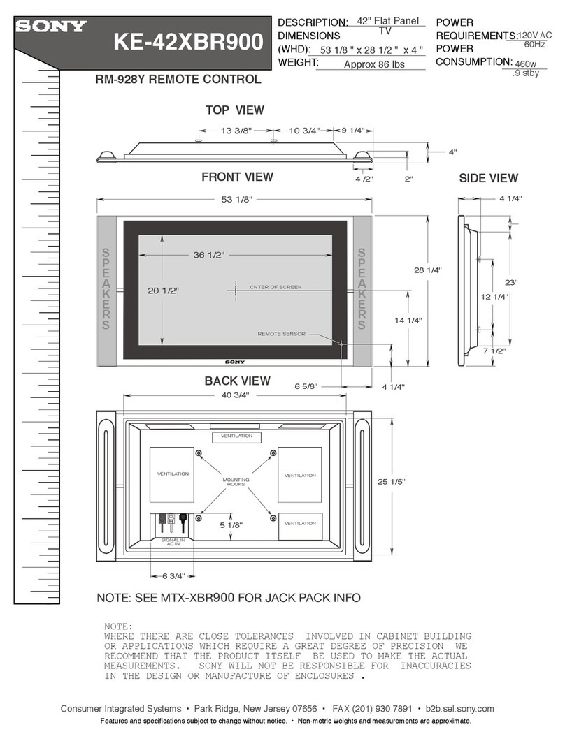
Dimensions, Weight & Power Consumption
MODEL CHASSIS HEIGHT
HEIGHT
w base WIDTH DEPTH
at panel Depth
at speakers DEPTH
w base WEIGHT
w base POWER USAGE
NORMAL STANDBY
LT-40164 VLP43+ 26" 27.3" 38.1" 1.9" 2.9" 11.5" 45.5 lbs 230W 0.4W
LT-46164 VLP43+ 29.0" 30.2" 43.3" " 2.9” " 51.7 lbs 280W "
LT-46265 VLP43++ " " " " 3.0" " 53.9 lbs " "
LT-55154 VLP43 33.3" 34.6" 50.9 " 2.9" 12.9" 63.6 lbs 295W "
LT-55164 VLP43+ " " " " 2.9" " 63.6 lbs " "
LT-55265 VLP43++ " " " " 3.0" " 65.8 lbs " "

Page 6
MODELS: LT-55154 / LT-40164 / LT-46164 / LT-55164 / LT-46265 / LT-55265
GWG - Green Wire Ground
(Earth Ground)
S2
S1
OPEN
GROUND
SUPPLY CONNECTOR GROUND
RECEIVER
INSULATED TABLE
TOUCH ALL
EXPOSED
METAL PARTS
AC MA
METER
L
N
SAFETY PRECAUTIONS
NOTICE:
Observe all cautions and safety related notes located inside the receiver cabinet and on the receiver chassis.
WARNING:
1. Operation of this receiver outside the cabinet or with the cover removed presents a shock hazard from the
receiver's power supplies. Work on the receiver should not be attempted by anyone who is not thoroughly
familiar with the precautions necessary when working on high voltage equipment.
2. Do not install, remove or handle the LCD panel in any manner unless shatterproof goggles are worn. People
not so equipped should be kept away while the panel is being handled. Keep the panel away from the body
while handling.
3. When service is required, observe the original lead dress. Where a short-circuit has occurred, replace those
components that indicate evidence of overheating.
4. If the LCD Panel is damaged, crystalline liquid may leak from the LCD panel and broken glass may be scat-
tered. The crystalline liquid is toxic. Avoid contact with your skin, eyes, or mouth. DO NOT touch the broken
glass or crystalline liquid with bare hands, as cuts, poisoning, and/or skin irritation may occur. DO NOT let
glass fragments or crystalline liquid get into your eyes or mouth. Should either contact your eyes or mouth,
rinse the contacted area thoroughly with water and consult your doctor.
5. DO NOT dispose of the TV with general household waste. Follow local laws and regulations for legal and
safe disposal of the TV. For disposal or recycling information, contact local authorities or the Electronic Indus-
tries Alliance at www.eiae.org.
Leakage current check
Before returning the receiver to the customer, it is recommended that leakage current be measured according to the
following methods.
1. Cold Check
With the alternating current (AC) plug removed from the AC source, place a jumper across the two AC plug
prongs. Connect one lead of an ohm meter to the AC plug and touch the other lead to each exposed metal part
(i.e. antennas, handle bracket, metal cabinet, screw heads, metal overlay, control shafts, etc.), particularly any
exposed metal part that has a return path to the chassis. The resistance of the exposed metal parts having a
return path to the chassis should be a minimum of 1Meg Ohm. Any resistance below this value indicates an
abnormal condition and requires corrective action.
2. Hot Check ...Use the circuit shown below to perform the hot check test.
1. Keep switch S1 open and connect the receiver to the measuring circuit. Immediately after connection, and
with the switching devices of the receiver in their operating positions, measure the leakage current for both
positions of switch S2.
2. Close switch S1, energizing the receiver. Immediately after closing switch S1, and with the switching devices
of the receiver in their operating positions, measure the leakage current for both positions of switch S2. Re-
peat the current measurements of items 1 and 2 after the receiver has reached thermal stabilization. The
leakage current must not exceed 0.5 milliamps (mA).

Page 7
MODELS: LT-55154 / LT-40164 / LT-46164 / LT-55164 / LT-46265 / LT-55265
DISASSEMBLY & PARTS REPLACEMENT
Back Cover Removal
NOTE: It is not necessary to remove the Stand for Back Cover removal.
1. Remove screws (A).
2. Lift the back cover from the TV.
A
A
A
A
HOLDER-PANEL Removal (for Panel or Front Bezel replacement)
1. Release HOLDER-PANEL from top center of TV.
NOTE: In case HOLDER-PANEL accidentally comes loose after Back Cover removal, be certain to re-install it
before reassembly.
HOLDER-PANEL
NOTE: Unless noted, instructions are for all models.
Illustrations may differ slightly depending upon the actual model being serviced.

Page 8
MODELS: LT-55154 / LT-40164 / LT-46164 / LT-55164 / LT-46265 / LT-55265
Stand Removal
NOTE: The Stand can be removed either before or after Back Cover removal.
1. Remove screws (B) and for 55” models (C) and lift TV off stand.
2. Place TV face down on a clean soft surface.
C
B
B
B B
C
Stand Removal with Back Cover on..
Stand Removal with Back Cover off.
(55” Models Only)
(55” Models Only)

Page 9
MODELS: LT-55154 / LT-40164 / LT-46164 / LT-55164 / LT-46265 / LT-55265
LCD Panel Replacement
NOTE: Do not remove the T-CON and LED-POWER PWBs. Replacement Panels Include these items.
1. Remove the Back Cover and Stand.
2. Remove all Major Components and assemblies along with the associated hardware and wiring.
3. Reverse the procedure to install a replacement.
Major Component Locations
PWB-MAIN
STAY-VESA-T
PWB-POWER
PWB-FILTER WLAN-MODULE
(VLP43+ &VLP43++)
PWB-LED
(VLP43 & VLP43+)
PWB-PREAMP2
(V43++)
T-CON
(Non-Replaceable)
ASSEMBLY-
SPEAKER-BOX BLUETOOTH
MODULE
(VLP43+ & VLP43++)
PWB-
CONTROL
BRACKET-BOTTOM
(Assembly) LED-POWER
(Non-Replaceable)
HOLDER-
PANEL

Page 10
MODELS: LT-55154 / LT-40164 / LT-46164 / LT-55164 / LT-46265 / LT-55265
ASSEMBLY-SPEAKER-BOX Removal
1. Remove screws (A).
A
ASSEMBLY-SPEAKER-BOX Disassembly
1. Remove the screws indicated on the Speaker Box by the arrows.
2. Separate the back from the front cabinet.
BEZEL Removal
1. VLP43++ Disconnect the SB connector
from the PWB-MAIN and release the wiring
harness from the taped locations leading to
the PWB-SBL.
2. Release the clips around the Bezel and
remove from the front.
3. VLP43++ Carefully feed the SBL wiring
harness from the back as the Bezel is be-
ing removed.
Note: Upon re-assembly be certain the wiring is
routed so it will not get caught in the chan-
nel of the Stand Mounting Bracket.
PWB-SBL Removal (VLP43++)
1. Remove the Bezel as described above.
Note: Use caution when removing the tape from
the wiring connector on the PWB-SBL. SB
PWB-SBL

Page 11
MODELS: LT-55154 / LT-40164 / LT-46164 / LT-55164 / LT-46265 / LT-55265
A
PWB-CONTROL
HOLDER-BUTTON
BUTTON-SIDE
PWB-CONTROL Removal
1. Release control assembly from TV by lifting up.
2. Remove screws (A).
PWB-FILTER Removal
1. For Panel replacement, remove the PWB-FILTER and Bracket assembly together by removing the screws
indicated on the bracket by arrows.
2. To remove the PWB-FILTER only, remove screw (B) and lift out from the right.
B
PWB-FILTER

Page 12
MODELS: LT-55154 / LT-40164 / LT-46164 / LT-55164 / LT-46265 / LT-55265
PWB-POWER Removal
1. Remove screw (A).
2. Swing PWB-POWER out and off from the top. A
PWB MAIN (Assembly) Removal
1. Remove screws (B) and (C).
2. Remove the PWB-MAIN assembly.
B
B
C
WLAN-MODULE Removal (VLP43+, VLP43++)
1. Unplug the WLAN-MODULE from the USB slot at the top of the PWB-MAIN.
WLAN-MODULE
(VLP43+, VLP43++)

Page 13
MODELS: LT-55154 / LT-40164 / LT-46164 / LT-55164 / LT-46265 / LT-55265
PWB-MAIN Replacement
1. Remove screws (A), (B) and nut (C).
2. Turn the assembly over and remove screws (D).
3. Before removing the PWB-MAIN, separate the Plastic Escutcheon from the Terminal Frame by gently prying
the point shown with a flat blade screwdriver.
NOTE: VLP43+ & VLP43++ models—When replacing the PWB-MAIN, transfer the WLAN-MODULE from the
original to the replacement PWB.
4. After replacement perform the SET SCREEN SIZE procedure in the Service Procedures section.
5. VLP43+, VLP43++ If the customer has calibrated the ISF (ADV) video settings, he may have the data
backed up to a USB memory device. If so, perform the RESTORE ISF SETTING procedure in the Service
Procedures section. If no backup memory is available, this step is not necessary.
IMPORTANT REPLACEMENT NOTE: If the customer has subscribed to VUDU (Internet program provider), the
original PWB must be returned to Mitsubishi. The customer should be instructed to contact VUDU to re-activate
their account after the replacement PWB has been installed.
C
A
A B B
D
Gently pry the Plastic Escutch-
eon from the Terminal Frame
before removing the PWB.

Page 14
MODELS: LT-55154 / LT-40164 / LT-46164 / LT-55164 / LT-46265 / LT-55265
(VLP43 & VLP43+ Models)
Apply Tape from the bottom edge of the
Speaker Box to prevent loose wiring from
being pinched by the Back Cover.
Dress harness between Pins
to prevent wiring from being
pinched by the Back Cover.
PINS
WIRING AND WIRE CLAMP LOCATIONS
T-CON
Black
LVDS Connector(s)
PWB-MAIN
Red
LVDS Connector
Blue
LVDS Connector
(VLP43 & 43+ Only)
WARNING: The
LVDS Cable(s) must be
installed as shown.
2 Cables VLP43/VLP43+
1 Cable VLP43++

Page 15
MODELS: LT-55154 / LT-40164 / LT-46164 / LT-55164 / LT-46265 / LT-55265
SERVICE PROCEDURES
REMOTE CONTROL USE FOR SERVICE
Many service functions and adjustments are accessed using the Remote Control.

Page 16
MODELS: LT-55154 / LT-40164 / LT-46164 / LT-55164 / LT-46265 / LT-55265
OPTION MENU
1. Press the <MENU> button on the remote control.
2. Press the buttons <2-4-7-0>. The screen will display the Option Menu.
3. Press <EXIT> to quit.
Option Menu
<MENU><2-4-7-0>
Initialize
Power Restore OFF
Production Mode OFF
Digital Signal Strength <1~9>
DM Software Vxx xxx.xx
Index xxx
Total hours of use 0
Digital Signal Strength Information
<MENU><2-4-7-0> “Digital Signal Strength”<ENTER>
Tuner
Frequency(MHz) 749
Signal Level <1~9>
Modulation 8VSB Air
Carrier Lock Locked
SNR 29.09
Correctable errors 0
Un Correctable errors 0
SERVICE LEVEL INITIALIZATION
Service Level Initialization is used to restore all customer menu,
video and audio settings to the original factory default condition.
1. Enter the Option Menu <MENU> <2-4-7-0>.
2. Select “Initialize” and <ENTER>.
DIGITAL SIGNAL INFORMATION
Information on the currently selected digital channel can be
displayed on screen.
Note: A digital channel received using the Antenna Input
must be selected first.
1. Select the Antenna Input and an active digital
channel.
2. Enter the Option Menu <MENU> <2-4-7-0>.
3. Select “Digital Signal Strength” and <ENTER>.
4. Press <EXIT> to quit.
Option Menu
<MENU><2-4-7-0>
Initialize
Deactivate Vudu
Power Restore OFF
Production Mode OFF
Digital Signal Strength <1~9>
NetCommand Software Vxx xxx.xx
Total hours of use 0
DEACTIVATE VUDU (Software Version 12.08 and higher)
This feature will deactivate the customer’s VUDU on-line sub-
scription. It should be used before TV ownership is changed.
NOTE: This feature is independent of the Initialize function.
1. Enter the Option Menu <MENU><2-4-7-0>.
2. Select “Deactivate Vudu” and <ENTER>.
3. The “Deactivate Vudu” text will momentarily turn red.
4. Press <EXIT> to quit.
5. The TV will register as deactivated the next time it is
connected to the internet.

Page 17
MODELS: LT-55154 / LT-40164 / LT-46164 / LT-55164 / LT-46265 / LT-55265
Service Tip:
Many customer generated symptoms, intermittent symptoms or no symptom found can be resolved by using the various
Reset and Initialization options. Before visiting the customer’s home ask the customer 1st perform a System Reset by
pressing the <POWER> button on the front panel and holding it for 8 seconds. If this does not resolve the issue, they
can perform an A/V Reset by pressing the <INPUT> + <VOL e>buttons on the front panel at the same time and holding
for 10 seconds. Then, if necessary, perform a user level Initialization by pressing <MENU><1-2-3> <ENTER> with the
remote. The customer should be made aware when settings and/or options will be reset. For more information, see the
chart below.
Reset Name When to use How to use ResultingAction
Remote Control
TV Layer Reset Returns the remote control TV layer
to normal operation. 1)
2)
3)
Set the slide switch to TV position.
Press and hold the <POWER> button until it flashes
twice then release the button.
Enter the code <0-0-9-3-5>.
Once the valid code has
been entered and
confirmed, the remote
contrrol has been reset.
Remote Control
TV
Volume/Mute
functions
Returns the volume and mute
functions of the remote control to TV
volume and mute for TV, Cable/Sat,
VCRand DVDlayers after the Audio
Lock for AV Receiver feature has
been used.
1)
2)
3)
Set the slide switch to TV position.
Press and hold the <POWER> button until it flashes
twice then release the button.
Enter the code <9-9-3>< VOL ٛ>.
The remote w ill now
operate the TV's volume
and mute when the slide
switch is in the TV,
CABLE/SAT, VCR or DVD
positions.
A/V Memory
Reset, by
individual input
When the audio or video
performance or settings for a single
input seemto be incorrect.
All Audio and Video
settings for the individual
input are reset except for
the Listen To, Language,
Balance and Closed
Caption settings.
A/V Reset, all
inputs When the audio or video
performance or settings for more
than one input seemto incorrect.
All Audio and Video
settings are reset to the
factory default settings. No
other menu options are
changed.
SystemReset To reset the TV w hen it does not
turn on or off, does not respond to
the remote control, front panel
buttons or has other unusual
symptoms.
TV Micro Re-boots. Note:
The changes made during
the current TV-On period
may be lost. All other
previous user settings are
not lost.
Initialize User
Level To reset all customer settings except
V-Chip All customer menu options
and A/V settings except V-
Chip & locked ISFare reset
to factory default.
Initialize -
Service Level Toreset allcustomer settings Allcustomer menu options
and A/V settings are reset
to factory default.
V-Chip
Passw ord
Bypass
If V-Chip passw ord is not known Password will be
bypassed. If in the V-Chip
menu, enter a new
password.
Unlock Front
Panel To unlock the front panel if it has
been locked in the V-Chip Menu. Front Panel becomes
operational. Other V-Chip
settings not changed. Note:
Cannot be performed w hile
in the Low Power mode
and the set is Off.
<MENU><2-4-7-0>. Highlight INITIALIZEand press
<ENTER>
Press <LAST>+<9> at the same time.
Press and hold the front panel <ENTER>button for 8
seconds.
<MENU> ٛAudio/Video ٛAV Re set <ENTER>
While viewing the TV, press the front panel buttons
<INPUT> + <VOL ٛ> at the same time and hold for 10
seconds.
Press the <POWER> button on the front panel and hold it
for 8 seconds.
Press <MENU><1-2-3><ENTER>
RESET / INITIALIZATION

Page 18
MODELS: LT-55154 / LT-40164 / LT-46164 / LT-55164 / LT-46265 / LT-55265
VLP43+ and VLP43++ models - If the customer has calibrated the ISF (ADV) video settings, the settings data
can be backed up on a USB memory device. If the settings are lost due to a Reset or Initialization procedure,
PWB-MAIN replacement or other reasons, the settings data can be restored.
Backup ISF Settings.
1. Insert a empty USB memory device into the USB slot.
2. Press the <MENU> button on the remote control. The Customer Menu will appear.
3. Press the <2-4-5-7> buttons. The Service Menu will appear.
4. Press the <0> button. The Data Selection Menu will appear. See below.
5. Use the <TS> buttons to select “BACKUP AND RESTORE ISF SETTING” and press <ENTER>.
6 Use the <TS> buttons to toggle to "Backup ISF Settings to USB” (Default).
7. While "Backup ISF Settings to USB” is displayed, press <ENTER>. The screen will flash the
message "Backup completed."
8. Remove the USB memory device and store it in a safe place.
9. Press <MENU> to exit.
Restore ISF Settings.
1. Insert the USB memory device with the backup data into the USB slot.
2. Press the <MENU> button on the remote control. The Customer Menu will appear.
3. Press the <2-4-5-7> buttons. The Service Menu will appear.
4. Press the <0> button. The Data Selection Menu will appear. See above.
5. Use the <TS> buttons to select “BACKUP AND RESTORE ISF SETTING” and press <ENTER>.
6. Use the <TS> buttons to toggle to “Restore ISF Settings From USB.”
WARNING: DO NOT press <ENTER> while "Backup ISF Settings to USB" is displayed. The data on the
USB will be overwritten and lost.
7. While “Restore ISF Settings From USB” is displayed, press <ENTER>. The screen will flash the
message "Restore completed." The TV will then turn off.
8. Remove the USB memory device before turning the TV back on.
SOUND PROJECTOR TRANSDUCER TEST
BACKUP AND RESTORE ISF SETTINGS
RED ONLY AND GREEN ONLY
SET SCREEN SIZE
BACKUP / RESTORE ISF SETTING MENU
Backup ISF Settings to USB
BACKUP / RESTORE ISF SETTING MENU
Backup ISF Settings to USB
Backup completed
BACKUP / RESTORE ISF SETTING MENU
Backup ISF Settings to USB
BACKUP / RESTORE ISF SETTING MENU
Restore ISF Settings from USB
Restore completed
BACKUP / RESTORE ISF SETTING

Page 19
MODELS: LT-55154 / LT-40164 / LT-46164 / LT-55164 / LT-46265 / LT-55265
The same PWB-MAIN is used for different screen sizes within a chassis family. When a PWB-MAIN is replaced,
the screen size must be set up. Failure to setup the correct screen size will result in poor picture performance.
1. Press the <MENU><2-4-5-7> buttons. The Service Menu will appear.
2. Press the <0> button. The Data Selection Menu will appear.
3. Use the <TS> buttons to select “SET SCREEN SIZE” and press <ENTER>.
4. Use the <TS> buttons to toggle to select the correct screen size and chassis of the model being ser-
viced.
5. Press <ENTER>.
6. The Screen Size indication will flash Red momentarily to indicate the selection has been saved.
Screen Size Menu
<MENU><2-4-7-0><0> “SELECT SCREEN SIZE”
SCREEN SIZE MENU
Screen Size : 55inch - VLP43
To toggle Screen Size, press “UP” or “DOWN”
To save the current value press “ENTER”
To exit this menu, press “EXIT” or “MENU”
SOUND PROJECTOR TRANSDUCER TEST
BACKUP AND RESTORE ISF SETTINGS
RED ONLY AND GREEN ONLY
SET SCREEN SIZE
SET SCREEN SIZE

Page 20
MODELS: LT-55154 / LT-40164 / LT-46164 / LT-55164 / LT-46265 / LT-55265
LED INDICATIONS AND SELF DIAGNOSTICS
The front panel Status LED provides an indication of the set’s operation and the possible cause of a malfunction.
SELF DIAGNOSTICS
A blinking red and yellow Status LED will indicate an Error Code that can help determine the cause of a circuit
failure.
• The number of Red blinks indicates the value of the MSD (tens digit) of the Error Code.
• The number of Yellow blinks indicates the value of the LSD (ones digit) of the Error Code.
Example: If the Error Code is “27”, the LED will continuously blink Red two times, followed by blinking Yellow
seven times.
See the following page for a list of Error Codes.
To perform a System Reset, press and hold the side Power button for 10 seconds. Or, unplug the set for 10 sec-
onds then restore power
NORMAL INDICATIONS
STATUS LED Indication Condition
Off Off (Standby)
Green Power On
Slow Blinking Green Power Off with Timer Set
Fast Blinking Green Power On Boot-up, AC Interrupted, System
Reset or Software Update (Wait from between
45 seconds to several minutes for blinking to
stop before proceeding)
STATUS LED Indication Condition
ABNORMAL INDICATION
Blinking Red then Blinking Yellow Circuit Failure (See Self Diagnostics)
Number of Red Blinks Number of Yellow Blinks
2 7
Error Code: 27
This manual suits for next models
5
Table of contents
Other Mitsubishi Electric Flat Panel TV manuals

Mitsubishi Electric
Mitsubishi Electric LT-40133 User manual

Mitsubishi Electric
Mitsubishi Electric LT-37131 User manual

Mitsubishi Electric
Mitsubishi Electric LT-40148 User manual

Mitsubishi Electric
Mitsubishi Electric LT-37132 User manual

Mitsubishi Electric
Mitsubishi Electric WD-52525 Use and care manual

Mitsubishi Electric
Mitsubishi Electric LT-46244 User manual

Mitsubishi Electric
Mitsubishi Electric LT-37131 User manual

Mitsubishi Electric
Mitsubishi Electric Unisen LT-52151 User manual

Mitsubishi Electric
Mitsubishi Electric LT-40133 User manual

Mitsubishi Electric
Mitsubishi Electric LT-40148 User manual