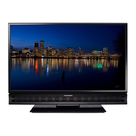
Mitsubishi Electric LT-40133 User manual

• Design specifications are subject to change without notice.
MITSUBISHI DIGITAL ELECTRONICS AMERICA, INC.
9351JeronimoRoad,Irvine,CA 92618-1904
Copyright © 2007 Mitsubishi Digital ElectronicsAmerica, Inc.
AllRightsReserved
CAUTION:
Before servicing this chassis, it is important that the service person read the "SAFETY PRECAUTIONS" and
"PRODUCTSAFETYNOTICE" containedinthis manual.
SerSer
SerSer
Servicevice
vicevice
vice
ManualManual
ManualManual
Manual
20072007
20072007
2007
MITSUBISHIELECTRIC
LCD FLAT PANELTELEVISION
VLP38 / VLP38+ / VLP38++ CHASSIS
•AVAnalog Inputs : VIDEOINJACK(RCAType)
& Outputs : AUDIOINJACK(RCAType)
: S-VIDEO IN JACK (Y/C separate)
: COMP/Y,Cr,Cb(RCAType)
: USB Input (5 meg pixel photo)
: Stereo Audio Outputs
• Inputs/Outputs : HDMITM 1.3 Inputs (digital)
480i, 480p, 720p, 1080i (60Hz)
1080p(24Hz, 30Hz, 60Hz)
: Digital Audio Output
(Dolby® Digital/PCM)
: IEEE-1394 I/O Jacks (V38++ only)
Dealer Playback Only
•HDMITM DigitalPCCompatibilty
: 640 x 480, 898 x 480, 800 x 600,
1064 x 600, 1024 x768, 1280 x 720,
1365 x 768, 1280 x 10s4 @ 60Hz
: 1920 x 1080 @ 24Hz, 30Hz, 60Hz
• Speakers : Two5½"x2¼"Oval
(4Ω 10W)
: Lead-Free solder PWBs
WD-52327
VLP38 Chassis
LT-40133
LT-46133
LT-52133
WD-52527
Pb Solder
Pb Solder
VLP38M Chassis
LT-40134
VLP38++ Chassis
LT-46244
LT-52244
SPECIFICATIONS
• Power Input : AC 120V, 60Hz
•Power Usage : See table on page 5
• Dimensions : See table on page 5
& Weight
• LCDPanel VLP38
: Resolution - 1920 x 1080
: Vertical Scan Range - 60Hz
VLP38+ / VLP38++
: Resolution - 1920 x 1080
: Vertical Scan Range - 120Hz
• Tuning : Digital/Analog Tuner
(NTSC/ATSC/QAM)
: Out of Band Tuner (VLP38++ only)
• Tuning Range : Air VHF - 2~13, UHF - 14~69
Analog Cable - 1~`25
Digital Cable - 1~135
•Antenna Input : 2 RF 75Ω unbalanced
LT-46244
VLP38+ Chassis
LT-46144
LT-52144
All manuals and user guides at all-guides.com
all-guides.com

• TVGUIDEand otherrelated marks areregistered marks ofGemstar-TV
GuideInternational, Inc. and/or one of its affiliates.
• HDMI™is a trademark of HDMILicensing, LLC
• CableCARDisa trademark ofCableTelevisionLaboratories, Inc.
• Dolbyand Dolby digitalare registeredtrademarks of Dolby Laboratories.
• DTV Link is a trademark of Consumer ElectronicsAssociation
All manuals and user guides at all-guides.com

Page 3
MODELS: LT-40133 / LT-46133 / LT-52133 / LT-40134 / LT-46144 / LT-52144 / LT-46244 / LT-52244
INTRODUCTION ................................................................................................................................5
Dimensions,weight, powerusage, etc............................................................................................5
PRODUCTSAFETY NOTICE ............................................................................................................. 5
SAFETY PRECAUTIONS .................................................................................................................6
DISASSEMBLY ..................................................................................................................................7
BackCoverRemoval .......................................................................................................................7
LCDStandRemoval ........................................................................................................................8
RearInputCoverRemoval ............................................................................................................... 8
WallMounting Brackets Removal ...................................................................................................9
Chassis& Stand Holder Removal....................................................................................................9
CHASSISDISASSEMBLY
PWB-DMCoverRemoval .............................................................................................................. 10
PWBsPower, Signal & DMRemoval ............................................................................................ 10
LT-52122<-5244PWB-DMRemoval ......................................................................................... 11
PWB-DMEndPlate Removal........................................................................................................11
LCDPANEL REPLACEMENT
ASSY-SIDE-TERMINALRemoval .................................................................................................. 12
BezelRemoval .............................................................................................................................. 12
40”& 46” Screen Brackets Removal ............................................................................................. 13
52”ScreenBrackets Removal ....................................................................................................... 14
SETUP,INTIALIZATION & ERROR CODES
UserControls................................................................................................................................15
OptionMenu & Digital Signal Strength ..........................................................................................16
Reset & Initalization ...................................................................................................................... 17
InitalSettings................................................................................................................................ 18
LedIndication ...............................................................................................................................19
ErrorCodes .................................................................................................................................. 20
USINGLEAD FREE SOLDER .......................................................................................................... 21
CHIPPARTSREPLACEMENT ......................................................................................................... 22
REPLACEMENTPARTS .................................................................................................................. 23
PartsOrdering .............................................................................................................................. 23
Criticaland WarrantyParts Designation........................................................................................ 23
PartsTolerance Codes.................................................................................................................. 23
Quick Reference List...................................................................................................................... 24
SERVICE PARTS LIST .................................................................................................................... 25
CIRCUITRYBLOCK DIAGRAMS ..................................................................................................... 32
MainPower Supply ....................................................................................................................... 32
PWB-DM DC to DC Supplies........................................................................................................33
OverallVideoSignal Path ............................................................................................................. 34
PWB-SIGNALVideo Select Circuitry ............................................................................................ 35
OverallAudioSignalPath.............................................................................................................. 36
PWB-TERMINALSound Select Circuitry ...................................................................................... 37
CONTENTS
All manuals and user guides at all-guides.com

MODELS: LT-40133 / LT-46133 / LT-52133 / LT-40134 / LT-46144 / LT-52144 / LT-46244 / LT-52244
Page 4
OverallControlCircuitry ................................................................................................................ 38
AutoInput/Output DetectCircuitry ................................................................................................ 39
Short Protect Circuitry .................................................................................................................. 40
SCHEMATICDIAGRAMS .....................................................................................................................
Digital Light Processing, Digital Micro Mirror Device and DLP are Trademarks of Texas Instruments.
Dolby and Dolby digital are registered trademarks of Dolby Laboratories.
DTV Link is a trademark of Consumer Electronics Association
HDMI, the HDMI logo and High-Definition Multimedia Interface are trademarks or registered trademarks of HDMI Licensing, LLC..
All manuals and user guides at all-guides.com

MODELS: LT-40133 / LT-46133 / LT-52133 / LT-40134 / LT-46144 / LT-52144 / LT-46244 / LT-52244
Page 5
INTRODUCTION
Thisservice manual providesservice instructions for LCD Flat Panel TV Models and Chassis:
PRODUCT SAFETY NOTICE
Many electrical and mechanical parts in television receivers have special safety related characteristics. These charac-
teristics are often not evident from visual inspection nor can the protection afforded by them necessarily be obtained by
usingreplacement componentsrated for higher voltage, wattage,etc.
Replacementparts which have special safety characteristics are identified in this service manual.
Electrical components having such features are identified by shading on the schematic diagram and parts list of this
service manual, and by marking on the supplementary sheet for this chassis to be issued subsequently. Therefore,
the replacement for any safety part should be identical in value and characteristics.
Pb Solder
The PWBs used in the VLP38, VLP38+ and VLP38++ chassis are constructed using Lead-Free
solder. When servicing use only recommended Lead-Free solder (refer to page 21).
LT-46244
MODEL CHASSIS HEIGHT HEIGHT
w/o base WIDTH DEPTH DEPTH
w/o base WEIGHT
w base POWER
USAGE
LT-40133 VLP38 26" 23.9" 37" 12.6" 5.6" 68.7 lbs 250W
LT-46133 VLP38 29" 26.9" 42.3 " 12.6" 5.6" 85.9 lbs 300W
LT-52133 VLP38 32.4" 30.4" 48" 14.2" 5.7" 98 lbs 370W
LT-40134 VLP38M 26" 23.9" 37" 12.6" 5.6" 68.7 lbs 250W
LT-46144 VLP38+ 29" 26.9" 42.3 " 12.6" 5.6" 85.9 lbs 325W
LT-52144 VLP38+ 32.4" 30.4" 48" 14.2" 5.7" 98 lbs 395W
LT-46244 VLP38++ 29" 26.9" 42.3 " 12.6" 5.6" 85.9 lbs 325W
LT-52244 VLP38++ 32.4" 30.4" 48" 14.2" 5.7" 98 lbs 395W
Product Demensions & Weight
All manuals and user guides at all-guides.com

Page 6
MODELS: LT-40133 / LT-46133 / LT-52133 / LT-40134 / LT-46144 / LT-52144 / LT-46244 / LT-52244
Leakage current check
Before returning the receiver to the customer, it is recommended that leakage current be measured according to the
followingmethods.
1. Cold Check
With the alternating current (AC) plug removed from the AC source, place a jumper across the two AC plug
prongs. Connect one lead of an ohm meter to the AC plug and touch the other lead to each exposed metal part
(i.e. antennas, handle bracket, metal cabinet, screw heads, metal overlay, control shafts, etc.), particularly any
exposed metal part that has a return path to the chassis. The resistance of the exposed metal parts having a
return path to the chassis should be a minimum of 1Meg Ohm.Any resistance below this value indicates an
abnormalconditionand requires correctiveaction.
2. Hot Check ...Use the circuit shown below to perform the hot check test.
1. Keep switch S1 open and connect the receiver to the measuring circuit. Immediately after
connection, andwith the switching devices of the receiver in theiroperating positions,measure the
leakage current for both positions of switch S2.
2. Close switch S1, energizing the receiver. Immediately after closing switch S1, and with the
switchingdevices ofthe receiver in their operating positions, measure the leakage current forboth
positions of switch S2. Repeat the current measurements of items 1 and 2 after the receiver has
reached thermal stabilization. The leakage current must not exceed 0.5 milliampere (mA).
SAFETY PRECAUTIONS
NOTICE: Observeall cautions andsafety related noteslocated inside thereceiver cabinet and on the receiver
chassis.
WARNING:
1. Operationof this receiver outside the cabinet orwith the coverremoved presents a shock hazard from the
receiver's power supplies. Work on the receiver should not be attempted by anyone who is not thoroughly
familiarwith the precautions necessary when working onhigh voltage equipment.
2. Donot install, remove or handle the LCD panel in any manner unlessshatterproof goggles areworn. People
not so equipped should be kept away while the panel is being handled. Keep the panel away from the body
whilehandling.
3. Whenservice is required, observethe original lead dress. Where a short-circuithas occurred, replace those
componentsthat indicate evidenceof overheating.
4. If the LCD Panel is damaged, crystalline liquid may leak from the LCD panel and broken glass may be
scattered. The crystalline liquid is toxic. Avoid contact with your skin, eyes, or mouth. DO NOT touch the
broken glass or crystalline liquid with bare hands, as cuts, poisoning, and/or skin irritation may occur. DO
NOT let glass fragments or crystalline liquid get into your eyes or mouth. Should either contact your eyes or
mouth, rinse the contacted area thoroughly with water and consult your doctor.
5. The fluorescent tubes in the panel contain mercury that is toxic and if broken should not be touched.
6. DO NOT dispose of the TV with general household waste. Follow local laws and regulations for legal and
safe disposal of theTV. For disposal or recycling information, contact local authorities or the Electronic
IndustriesAllianceat www.eiae.org.
All manuals and user guides at all-guides.com
all-guides.com

MODELS: LT-40133 / LT-46133 / LT-52133 / LT-40134 / LT-46144 / LT-52144 / LT-46244 / LT-52244
Page 7
Back Cover Removal
Back Cover Removal Procedure
1) Remove24 screws(A) from the back cover
(21 screws on 40” models).
2) Pull the back cover from the TV.
Back Cover Installation
Reversetheremovalprocedure.
52” MODELS
40” & 46”
MODELS
LT-40133
LT-40134
LT-46133
LT-46144
LT-46244
LT-52133
LT-52144
LT-52244
All manuals and user guides at all-guides.com

Page 8
MODELS: LT-40133 / LT-46133 / LT-52133 / LT-40134 / LT-46144 / LT-52144 / LT-46244 / LT-52244
LCD Stand Removal
Stand Removal Procedure
1) Lay the unit face down on a soft non-scratching surface.
2) Remove4 screws (B)
3) Pull the stand from the bottom of the unit.
Rear Input’s Cover Removal
1) Remove4 screws(c)
2) Carefullypull offthe rear input’scover.
All manuals and user guides at all-guides.com

MODELS: LT-40133 / LT-46133 / LT-52133 / LT-40134 / LT-46144 / LT-52144 / LT-46244 / LT-52244
Page 9
Wall Mounting Brackets Removal
1) Remove8 screws(D) (4 on 52” models).
2) Lift the mounting brackets from the unit.
Chassis & Stand Holder Removal
Chassis Removal Procedure
1) Remove6 screws(A).
2) Remove two screws (B). (40 & 46 inch models only)
3) Unplug all inter-connecting cabels and lift the chassis from the unit.
Stand Holder Removal
1) Removescrews (c).
2) Lift the stand holder from the unit..
All manuals and user guides at all-guides.com

Page 10
MODELS: LT-40133 / LT-46133 / LT-52133 / LT-40134 / LT-46144 / LT-52144 / LT-46244 / LT-52244
PWB-DM Cover Removal
1) Removescrews (F) toremove theLVDS Cover.
2) Removescrews (E)to removethe DM-COVERand EARTHPLATE.
3) Liftthe PWB-DM Cover from the unit.
Chassis Disassembly
PWBs Power, Signal & DM Removal
1) PWB-POWERremove (10)screws (D).
2) PWB-SIGNALremove 6screws (C).
3) PWB-DMremove 3 screwS (A) fromthe end bracketand service connector cover,
and screws (B) from the PWB-DM.
NOTE: Additionaldisassembly required inLT-52244(Seefollowing page)
All manuals and user guides at all-guides.com

MODELS: LT-40133 / LT-46133 / LT-52133 / LT-40134 / LT-46144 / LT-52144 / LT-46244 / LT-52244
Page 11
LT-46144, LT-46244, LT-52144 & LT-52244 PWB-DM Removal
1) Remove4 screws (C) to remove the shield top.
2) Remove3 screws (A) from the end support plate.
3) Remove12 screwsfrom the PWB-DM
2) Carefully lift the PWB-DM from the unit.
PWB-DM End Support Plate Removal
1) Removetwo hexnuts (G).
2) Remove5 screws (H) from theend support plate.
3) Pull the support plate away from the DM.
All manuals and user guides at all-guides.com
all-guides.com

Page 12
MODELS: LT-40133 / LT-46133 / LT-52133 / LT-40134 / LT-46144 / LT-52144 / LT-46244 / LT-52244
LCD Panel Replacement
ASSY-SIDE- TERMINAL Removal
1) Unplugall connecting cables.
2) Slide the assembly towards the top of the unit.
Bezel Removal
1) Removescrews (A) along the top, bottom and
sides of the Bezel. (The number of screws and
location varies with screen size.)
2) Lift the LCD ScreenAssembly from the Bezel.
40 Inch models
Bezel removal
46 Inch models
Bezel removal
All manuals and user guides at all-guides.com

MODELS: LT-40133 / LT-46133 / LT-52133 / LT-40134 / LT-46144 / LT-52144 / LT-46244 / LT-52244
Page 13
40 Inch
models
52 Inch models
Bezel removal
40 & 46 Inch Screen Brackets Removal
1) Removemounting screws from the upper, lower,
cornerand side mounting brackets.
2) Lift the brackets from the Screen assembly.
All manuals and user guides at all-guides.com

Page 14
MODELS: LT-40133 / LT-46133 / LT-52133 / LT-40134 / LT-46144 / LT-52144 / LT-46244 / LT-52244
46 Inch
models
52 Inch
models
52 Inch Screen Brackets Removal
1) Removemounting screws frim the upper,lower
and side mounting brackets.
2) Lift the brackets from the Screen assembly.
All manuals and user guides at all-guides.com

MODELS: LT-40133 / LT-46133 / LT-52133 / LT-40134 / LT-46144 / LT-52144 / LT-46244 / LT-52244
Page 15
Partially Illuminated Fully Illuminated
REMOTE CONTROLS
VLP38/VLP38+ VLP38++
SIDE CONTROL PANEL
USER CONTROLS
All manuals and user guides at all-guides.com

Page 16
MODELS: LT-40133 / LT-46133 / LT-52133 / LT-40134 / LT-46144 / LT-52144 / LT-46244 / LT-52244
Item Description
• Initial - Resets Settings
• PowerRestore- PowerRestoreON/OFF
• NetcommandSoftware-Displays software version
• Digital Signal Strength - Digital Signal Data (not for
analogsources)
SNR Recommended Levels:
VSB = 15 to 35
64 QAM = 22 to 34
256 QAM = 27 to 37
1. Press the “MENU” button on the remote hand unit.
2. Press the buttons “2”, “4”, “7” and “0” in order. (The screen will change to the option menu.)
OPTION MENU
Example of Digital Signal Strength Display
Signal Quality
Index (0-100)
Signal Noise
Ratio
Tuner 0 Tuner 1 OOB Tuner
Frequency (MHz): 597 0 75.2
Signal Level: 8 0 0
Modulation: 256 QAM Unknown
Carrier Lock: Locked Unknown Locked
SQI 100 0
SNR 34.3 0 23.77
Correctable errors: 0 0
UnCorrectabel errors: 0 0
Digital Signal Strength
1.Tune toa DigitalChannel
2. From the Option menu scroll down and highlight Digital Signal Strength
3. Press Enter
All manuals and user guides at all-guides.com
all-guides.com

MODELS: LT-40133 / LT-46133 / LT-52133 / LT-40134 / LT-46144 / LT-52144 / LT-46244 / LT-52244
Page 17
NOTE: DuringInitialization, the set will
reboot. Waituntil the PowerLED stops
flashingbefore unplugging orpowering
ON theTV.
SERVICE TIP:
Many customer generated symptoms, intermittent symptoms or no symptom found can be resolved by using the
various Reset and Initialization options. Before visiting the customer’s home ask the customer 1st to try the System
Reset button on the control panel and if this does not resolve the issue, then they can perform an A/V Reset by
pressing the Guide + Format buttons on the front panel at the same time. Then, if necessary, perform a user level
Initialization bypressing MENU-123-ENTER with theremote. The customer should be made aware whensettings
and/or options will be reset. For more information, see the chart below.
RESET & INTIALIZATION
RESET / INITIALIZATION GUIDE
Reset Name When to use How to use Resulting Action
Remote Control TV
Layer Reset Returns the remote control TV
layer to normal operation.
(
1
)
(
2
)
(
3
)
(3)
Set the slide switch to TV position.
Press and hold the POWER button until it
flashes twice then release the button.
Enter the code 0 0 9 3 5.
Once the valid code has been entered
and confirmed, the remote control has
been reset.
Remote Control TV
Volume/Mute
functions
Returns the volume and mute
functions of the remote control to
TV volume and mute for TV,
Cable/Sat, VCR and DVD layers
after the Audio Lock for AV
Receiver feature has been used.
(
1
)
(
2
)
(
3
)
(3)
Set the slide switch to TV position.
Press and hold the POWER button until it
flashes twice then release the button.
Enter the code 9 9 3 VOL UP.
The remote will now operate the TV's
volume and mute when the slide
switch is in the TV, CABLE/SAT, VCR
or DVD positions.
A
/V Memor
y
Reset,
by individual input When the audio and or video
settings for a single input seems
to incorrect
MENU --> Audio/Video--> AV Reset All Audio and Video settings for the
individual input are reset except for the
Listen To, Language, Balance and
Closed Caption settings.
A/V Reset, all
inputs To reset audio and video
adjustments for all inputs to the
original factory settings.
While viewing the TV, press the front panel
buttons GUIDE + FORMAT at the same time. All Audio and Video settings are reset
to the factor
y
default settin
g
s. No other
menu options are changed.
System Reset To reset the TV when it does not
turn on or off, does not respond
to the remote control, front panel
buttons or has other unusual
symptoms.
Press the SYSTEM RESET button on the front
panel with a pointed object such as a pencil or
paperclip.
TV Micro Re-boots. Note: The chan
g
es
made during the current TV-On period
may be lost. All other previous user
settings will not be lost.
Initialize User Level To reset all customer settings
except V-Chip Press MENU - 123 - ENTER All customer menu options and A/V
settings except V-Chip are reset to
factory default.
Initialize - Service
Level To reset all customer settings MENU - 2470. Highlight INITIALIZE and press
ENTER All customer menu options and A/V
settings are reset to factory default.
V-Chip Password
Bypass If V-Chip password is not known Press QV + 9 at the same time. Password will be bypassed. If in the V-
Chip menu, enter a new password.
Unlock Front Panel To unlock the front panel if it has
been locked in the V-Chip Menu. Press and hold the front panel MENU button
for 8 seconds. Front Panel becomes operational.
Other V-Chip settings not changed.
Note: Cannot be performed while in
the Low Power mode and the set is
Off.
All manuals and user guides at all-guides.com

Page 18
MODELS: LT-40133 / LT-46133 / LT-52133 / LT-40134 / LT-46144 / LT-52144 / LT-46244 / LT-52244
INITIAL SETTINGS
Setting after Initialization
Audio/Video Time Zone Eastern
Video Daylight Savings Applies
Picture Mode Brillant Timer Gray out
Brilliant Contrast 100% Timer Off
Brilliant Brightness 50% Daylight Savings daily
Color tint 50% Time 12:00pm
Tint 50% Device ANT-1
Sharpness 50% Channel 2
Brilliant Color Temp High Energy mode (High or Low) High Power
Deep Fiield Imager (only VLP38M/VLP38++) On Version mode VLP38XXX XX
Audio Inputs Menu
Speakers AV Rec Name
Bass 50% Ant-1 & Ant-2 On
Treble 50% Input-1~ 3 Gray out
Balance 50% Comp-1~3 Gray out
Surround Off HDMI-1~4 (only VLP38M/VLP38++) Gray out
Listen To (analog only) Stereo Learn (only VLP38M/VLP38++)) Gray out (ant, 1394)
Language (digital only) English AV Receiver (only VLP38M/VLP38++) Gray until sensed
Level sound On Learn --
Reset (current source only) ** Learn name --
PerfectColor On Assign Input 1~4 Gray out
PerfectTint (only VLP38M/VLP38++) On Guide
Global Guide Off
Video Mute On Devices Cagle box
Film Mode Auto Zip Code 00000
Video Noise (off-low-mid-high) Medium Order --
Sharp Edge (only VLP38M/VLP38++) On Parent Lock Menu
Backlight 100% U.S. Ratings
Captions Menu Lock Off
Closed Captions TV Trating TV-PG
Analog Captions On if Mute FV- Fantasy Violence unchecked
Background Gray D-Sexual Dialog unchecked
Digital Cations On if mute L-Adult Language unchecked
Appearance Default S- Sexual Situations unchecked
Digital V-Violence unchecked
Font Font 3 Movie Ratings PG
Size Large Other Ratings Gray until available
Color tint White Other Ratings Off
Background Black Rating Group TBD
Opacity
r
ansluctent Rating TBD
Background Opacity
r
ansluctent Time
Setup Menu Lock by Time Off
Language (idioma) English Lock Time 12:00pm
Scan Unlock Time 12:00pm
Ant1 (Air or Cable) -- Front Panel
Ant2 (Air or Cable) -- Front Button Lock Off
Start TV Volume 50%
Edit Format
Channel in Memory 2, added Ant-1,2 (480i) Stretch
Name -- Ant-1,2 (HD Digital) Standard
FAV1~FAV6 unchecked Input-1,2,3 Standard
Clock Comp-1,2,3 Standard
Settings Manual HDMI01,2,3,4 (Video or PC) Standard
Time 12:00pm 1394 Devices (Dealer use only) Standard
Date 1/1/2007 USB Photo Standard
All manuals and user guides at all-guides.com

MODELS: LT-40133 / LT-46133 / LT-52133 / LT-40134 / LT-46144 / LT-52144 / LT-46244 / LT-52244
Page 19
LED Indicator Diagnostics
Thefrontpanel LEDs provide anindicationof theset’soperation, and thepossiblecause of amalfunction. There are two
front panel LEDs, “Power” and “Status”. The LED display shows the current status or indicates a possible malfunction.
A/V INITIAL SETTINGS
A/V Memory Ant Video Input Component
In
p
ut 1394 HDMI
(
Video
)
HDMI
(
PC
)
USB
(
JPEG
)
Picture Mode Brilliant Brilliant Brilliant Brilliant Brilliant Brilliant Brilliant
Brilliant Contrast MAX MAX MAX MAX MAX MAX MAX
Brilliant Brightness Center Center Center Center Center Center Center
Color Center Center Center Center Center Center Center
Tint Center Center Center Center Center Center Center
Sharpness Center Center Center Center Center Center Center
Color Temp. High High High High High High High
Perfect Color Center Center Center Center Center Center Center
Perfect Tint
(
VLP38M/VLP38++
)
Center Center Center Center Center Center Center
Deep Field imager
(
VLP38M/VLP38++
)
On On On On On On On
Back Light MAX MAX MAX MAX MAX MAX MAX
V
ideo Noise Medium Medium Medium Medium Medium Medium Medium
Film Mode Off Off Off Off Off Off Off
SharpEdge
(
VLP38M/VLP38++
)
On On On On On On On
Bass Center Center Center Center Center Center n/a
Treble Center Center Center Center Center Center n/a
Balance Center Center Center Center Center Center n/a
Surround Off Off Off Off Off Off n/a
Listen To stero n/a n/a n/a n/a n/a n/a
Level Sound On On On On On On n/a
Language
(
Di
g
ital Onl
y)
English n/a n/a English n/a n/a n/a
V
ertical Position n/a n/a n/a n/a n/a Center n/a
Horizontal Position n/a n/a n/a n/a n/a Center n/a
Fine Detail n/a n/a n/a n/a n/a Center n/a
NORMAL LED INDICATIONS
POWER/TIMER LED STATUS
LED CONDITION
Off Off Off (standby mode)
Blinks Blue (Fast) Off Initializing (10~65 seconds) (AC off)
Blue Off Power On
Blink Blue (Slow) Off Power On Timer is set
ABNORMAL LED INDICATIONS
POWER/TIMER LED STATUS
LED CONDITION
Off Blinks Red Fan stopped (LT-46244/LT-52244 Only)
Circuit failure
(
short
)
Off Red LCD PON-short or Inverter short
LVDS cable disconnected, chassis to panel.
All manuals and user guides at all-guides.com

Page 20
MODELS: LT-40133 / LT-46133 / LT-52133 / LT-40134 / LT-46144 / LT-52144 / LT-46244 / LT-52244
3. Error Code Operational Check
Note: TheTV must be in “ShutDown” andnot have been switched Off,to performthe ErrorCode Opera-
tionalCheck. When the TV is switched Off, the code automatically resets to “12” No Error.
Pressing the front panel “INPUT” and “MENU” buttons at the same time, and holding for 5 seconds,
activates the Error Code Mode. The “POWER LED” flashes denoting a two digit Error Code, or indicating no
problem has occurred since the last Initialization.
Note: The front panel buttons must be used, NOTthose on the Remote Control.
•Thenumber offlashes indicatesthe valueof the MSD (tens digit) of the Error Code.
•Theflashing then pauses for approximately1/2 second.
•TheLED thenflashes indicatingthe valueof theLSD (ones digit) of the Error Code.
•The Error Code is repeated a total of 5 times.
(EXAMPLE) - When the error code is 35, the LED flashes as follows
ERROR CODES
Error Code Description ٛConnector
12 No error since last power On
27 Inverter short detected (IC7A01 pin 116 = High when short) PB-PD-PF
28 FPGA download failure (IC7A01 pin 44 = Low when short)
29 FRC communication error (VLP38+/VLP38++) - (3.3V-SDA&SCL) VR
35 DM Fan stopped (VLP38++ only) JD
44 Disconnected LVDSI cable between DM and LCD module VR-CN1
47 DM temperature too high
48 LCD Panel short detected (IC7A01 pin 124 = Low when short) PB-PG
58 Signal Short Detected (IC7A01 pin 89 = Low when short)
59 DM short detected ( (IC7A01 pin 125 = Low when short)
All manuals and user guides at all-guides.com
Other manuals for LT-40133
1
This manual suits for next models
7
Table of contents
Other Mitsubishi Electric Flat Panel TV manuals

Mitsubishi Electric
Mitsubishi Electric Unisen LT-55154 User manual

Mitsubishi Electric
Mitsubishi Electric LT-37132 User manual

Mitsubishi Electric
Mitsubishi Electric LT-46244 User manual

Mitsubishi Electric
Mitsubishi Electric LT-3280 User manual

Mitsubishi Electric
Mitsubishi Electric LT-40133 User manual

Mitsubishi Electric
Mitsubishi Electric LT-40148 User manual

Mitsubishi Electric
Mitsubishi Electric LT-37131 User manual

Mitsubishi Electric
Mitsubishi Electric LT-40148 User manual

Mitsubishi Electric
Mitsubishi Electric Unisen LT-52151 User manual

Mitsubishi Electric
Mitsubishi Electric WD-52525 Use and care manual