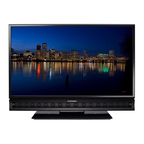
Mitsubishi Electric LT-37131 User manual

MITSUBISHI DIGITAL ELECTRONICS AMERICA, INC.
9351 Jeronimo Road, Irvine, CA 92618-1904
Copyright © 2006 Mitsubishi Digital ElectronicsAmerica, Inc.
AllRightsReserved
CAUTION:
Before servicing this chassis, it is important that the service person read the "SAFETY PRECAUTIONS" and
"PRODUCTSAFETYNOTICE"containedinthismanual.
MITSUBISHIELECTRIC
SerSer
SerSer
Servicevice
vicevice
vice
ManualManual
ManualManual
Manual
20062006
20062006
2006
SPECIFICATIONS
LCD FLAT PANEL TELEVISION
VLP33 / VLP33+ CHASSIS
• Power Input : 120V, 60Hz
• Power Usage :See Chart on Page 5
• Dimensions :See Chart on Page 5
& Weight
• LCD Panel : Resolution - 1920 x 1080
: Vertical Scan Range - 60Hz
• Tuning : Digital/Analog Tuner - 1 (NTSC/ATSC/QAM)
Out Of Band Tuner - 1 (For CableCARD™)
• Tuning Range : Air VHF - 2~13, UHF - 14~69
Analog Cable - 1~125
Digital Cable - 1~135
• Antenna Inputs: 2-RF, 75Ωunbalanced (Digital or Analog)
• A/V Inputs : Composite or S-Video (NTSC, 480i)
(Analog 1 Front, 2 Rear
w/Stereo Component, EIA770.3 Standard
Audio) (480i, 480p, 720p, 1080i)
VLP33 - 2 Rear
VLP33+ - 3 Rear
• PC DVI-I Input : Analog orDigital-VGA, W-VGA,SVGA,W-
(w/Analog SVGA, XGA, 1280x720 (720p) at 60 Hz
Stereo Audio) DigitalOnly -SXGA, WXGAat 60Hz
1920x1080 (1080p) at 24/30/60Hz:
• Inputs/Outputs: HDMI™, EIA861 B Standard
(Digital) 480p / 720p / 1080i at 60Hz
1080p at 24/30/60Hz:
w/DVIAnalog StereoAudio, 2 Rear
IEEE1394, MPEG-2, 2 Rear
Digital Audio Output (Dolby® Digital/PCM)
1 Rear, Coaxial
• Outputs : Stereo Audio Output, 1 Rear (Fixed)
RecordA/V Output, 1 Rear
NetCommand®/G-LINK™ IR Emitter
VLP33 - None
VLP33+ - 1 Rear, Mini Jack
• Speakers : Stereo, 2-way, 5.5"x2.2", 10W x 2, 6Ω
:PWBs use lead Free Solder
• TV GUIDE and other related marks are registered marks of
Gemstar-TV Guide International, Inc. and/or one of its affiliates.
• HDMI™ is a trademark of HDMI Licensing, LLC
• CableCARD is a trademark of Cable Television Laboratories, Inc.
• Dolby and Dolby digital are registered trademarks of Dolby
Laboratories.
• DTV Link is a trademark of Consumer Electronics Association
VLP33 VLP33+
LT-37131 LT-37132
LT-46131 LT-46231
LT-46231
Pb Solder
• Weight and dimensions are approximate.
• Design specifications are subject to change without notice.


MODELS: LT-37131 / LT-37132 / LT-46131 / LT-46231
Page 3
CONTENTS
PRODUCTSAFETYNOTICE ............................................................................................................. 5
SAFETYPRECAUTIONS ................................................................................................................... 5
RESET/INITIALIZATION...................................................................................................................7
OPTIONMENU ................................................................................................................................11
FRONTLEDINDICATOR DIAGNOSTICS ........................................................................................ 12
CableCARD ..................................................................................................................................... 13
TVGUIDEON SCREEN ................................................................................................................... 15
USINGLEADFREE SOLDER .......................................................................................................... 18
DISASSEMBLY ................................................................................................................................19
REPLACEMENTPARTS .................................................................................................................. 26
QuickReference ........................................................................................................................... 27
Service Parts List.......................................................................................................................... 28
CIRCUIT BLOCKDIAGRAMS .......................................................................................................... 37
INTERCONNECTSCHEMATIC BLOCKDIAGRAM

MODELS: LT-37131 / LT-37132 / LT-46131 / LT-46231
Page 4

MODELS: LT-37131 / LT-37132 / LT-46131 / LT-46231
Page 5
INTRODUCTION
Thisservice manual provides serviceinstructionsfor LCD Flat PanelTVModels and Chassis:
PRODUCT SAFETY NOTICE
Manyelectrical and mechanicalpartsin television receivers havespecialsafety related characteristics. Thesecharacter-
istics are often not evident from visual inspection nor can the protection afforded by them necessarily be obtained by
usingreplacement components rated for highervoltage,wattage,etc.
Replacementparts which havespecialsafety characteristics are identifiedin this service manual.
The replacement for any safety part should be identical in value and characteristics.
SAFETY PRECAUTIONS
NOTICE: Observe all cautions and safety related notes located inside the receiver cabinet and on the
receiverchassis.
WARNING:
1. Operationofthisreceiveroutsidethecabinetorwiththe cover removed presents a shock hazard
fromthe receiver's power supplies. Work onthereceiver should not be attemptedbyanyonewho is
notthoroughlyfamiliarwiththeprecautionsnecessarywhenworking on high voltage equipment.
2. Donotinstall,removeorhandletheLCDpanelinany manner unless shatterproof goggles are
worn.People not soequippedshould be kept awaywhilethe panel is beinghandled. Keep
thepanelawayfrom the body while handling.
3. Whenserviceisrequired,observetheoriginallead dress. Where a short-circuit has occurred,replace
thosecomponentsthatindicateevidenceofoverheating.
4. If the LCD Panel is damaged, crystaline liquid may leak from the LCD panel and broken glass may be
scattered. The crystaline liquid is toxic.Avoid contact with your skin, eyes, or mouth.
DO NOT touch the broken glass or crystaline liquid with bare hands, as cuts, poisoning, and/or skin irria-
tion may occur. DO NOT let glass fragments or crystaline liquid get into your eyes or mouth. Should either
contact your eyes or mouth, rinse the contacted area thouroughly with water and consult your doctor.
5. The fluorescent tubes in the panel contain mercury that is toxic and if broken should not be touched.
6. DONOT dispose of the TV withgeneralhouseholdwaste. Followlocallaws and regulations for legal and
safe disposal of the TV. For disposal or recycling information, contact local authorities or the Electronic
IndustriesAllianceat www.eiae.org.
MODEL CHASSIS SCREEN
(16:9) HEIGHT
(wo/STAND) HEIGHT
(w/STAND) WIDTH DEPTH
(wo/STAND) DEPTH
(w/STAND) WEIGHT
(w/STAND) POWER
USAGE
LT-37131 VLP33 37" 24.4" 26.8" 36" 5.3" 13.3" 58.8 lbs. 250W
LT-37132 VLP33+ 37" 24.4" 26.8" 36" 5.3" 13.3" 58.8 lbs. 250W
LT-46131 VLP33 46" 29.3" 31.7" 44.6" 5.7" 14.1" 89 lbs. 350W
LT-46231 VLP33+ 46" 29.3" 31.7" 44.6" 5.7" 14.1" 89 lbs. 350W

Page 6
MODELS: LT-37131 / LT-37132 / LT-46131 / LT-46231
Leakage current check
Beforereturning the receiver to thecustomer, leakage currentshouldbemeasured using following methods.
1. Cold Check
Withthe alternating current (AC)plugremoved from theACsource,placea jumper across thetwoAC plug prongs.
Connect one lead of an ohm meter to theAC plug and touch the other lead to each exposed metal part (i.e. anten-
nas, handle bracket, metal cabinet, screw heads, metal overlay, control shafts, etc.), particularly any exposed metal
part that has a return path to the chassis. The resistance of the exposed metal parts having a return path to the
chassis should be a minimum of 1Meg Ohm.Any resistance below this value indicates an abnormal condition
andrequirescorrectiveaction.
2. Hot Check ...Use the circuit shown below to perform the hot check test.
1. Keep switch S1 open and connect the receiver to the measuring circuit. Immediately after
connection,and with the switching devices ofthereceiverintheiroperating positions, measure
the leakage current for both positions of switch S2.
2. Close switch S1, energizing the receiver. Immediately after closing switch S1, and with the
switchingdevices of the receiver in theiroperatingpositions,measuretheleakage current for both
positions of switch S2. Repeat the current measurements of items 1 and 2 after the receiver has
reached thermal stabilization. The leakage current must not exceed 0.5 milliampere (mA).

MODELS: LT-37131 / LT-37132 / LT-46131 / LT-46231
Page 7
RESET / INITIALIZE GUIDE
Reset Name When to use How to use Resulting Action
Remote Control
TV Layer Reset Returns the remote control TV
layer to normal operation.
(
1
)
(
2
)
(
3
)
(
3
)
Set the slide sw itch to TV position.
Press and hold the POWER button until it
flashes twice then release the button.
Enter the code 0 0 9 3 5.
Once the valid code has been
entered and confirmed, the remote
control has been reset.
Remote Control
TV Volume/Mute
functions
Returns the volume and mute
functions of the remote control
to TV volume and mute for TV,
Cable/Sat, VCR and DVD
layers after the audio lock for
AV Receivers feature has
been used.
(
1
)
(
2
)
(
3
)
(3)
Set the slide sw itch to TV position.
Press and hold the POWER button until it
flashes twice then release the button.
Enter the code 9 9 3 VOL UP.
The remote w ill now operate the TV's
volume and mute w hen the slide
sw itch is in the TV, CABLE/SAT,
VCR or DVD positions.
A/V Memory
Reset, single input When the audio and or video
settings for a single input
seems to incorrect
MENU -->Audio/Video--> AV Reset All Audio and Video settings for the
individualinput are reset except for
the Listen To and Language, audio
Balance and Closed Caption
settings.
A/V Reset, all
inputs To reset audio and video
ad
j
ustments for all inputs to the
original factory settings.
While view ing the TV, press the front
panel buttons GUIDE and FORMAT at
the same time.
A
ll Audio and Video settin
g
s includin
g
Listen To and Language, Closed
Captions settings and Format
settings are returned to the original
factory settings.
System Reset To reset the TV when it does
not turn on or off, does not
respond to the remote control,
front panel buttons or has
audio but no video.
Press the SYSTEM RESET button on the
front panel w ith a pointed object such
as the point of pencil or end tip of a
paperclip.
The changes you made most
recently, before using the SYSTEM
RESET, may be lost. Changes you
made previously, how ever, are not
lost.
TV Reset To reset all customer settings Press MENU-1-2-3-ENTER All customer settings except V-Chip
are reset.
Initialize - User
Level To reset all consumer adjusted
settings and memories to the
original factory defaults.
Press FORMAT and INPUT buttons on
the front control panel at the same time. All memories and settings outlined in
the Ow ner's Guide w ill need to be
set again.
Initialize - Service
Level To reset all consumer adjusted
settings and memories to the
original factory defaults.
MENU + 2470. Highlight INITIALIZE and
press ENTER All memories and settings outlined in
the Ow ner's Guide w ill need to be
set again. Also erases V-CHIP
passw ord
Factory Restore To recover from
data/adjustment errors in the
ISF menu
MENU + 2457 + 0. Highlight RESTORE
FACTORY DEFAULTS and press ENTER All service, user, ISF data is set back
to factory defaults.
NOTE: DuringInitialization,theset will
reboot. WaituntilthePowerLEDstops
flashingbeforeunpluggingorpowering
ON theTV.
Front Panel Initialization
While the unit is ON, pressing the FORMAT and INPUT buttons simultaneously will immediately start the
Initialization sequence. The TV will reboot once the initialization sequence is completed. Front Panel
Initialization will reset ALL user settings to the factory setting.
SERVICETIP:
Many customer generated symptoms, intermittent symptoms or no symptom found can be resolved by system
reset or initialization. Before visiting the customer’s home ask the customer 1st to try the System Reset button
on the control panel and if this does not resolve the issue, then they can use the front panel initialization by
pressing the FORMAT and INPUT buttons simultaneously. Other items that can be reset or initialized are
detailed in the guide below. Use it to avoid making unnecessary calls that may not be covered under warranty.
RESET & INITIALIZATION

Page 8
MODELS: LT-37131 / LT-37132 / LT-46131 / LT-46231
Front Panel Guide
FRONT PANEL
1) SYSTEM RESET1- Reboots Set
(Same as Cycling AC Power)
Power LED will flash for about
1 minute.
2) A/V RESET2<FORMAT+GUIDE>
Resets all Customer Audio/Video Settings
FORMAT GUIDE INPUT
ENTER CANCEL
SYSTEM
RESET MENU
VOLUME
ADJUST
CH
ADJUST
3) INITIAL2<FORMAT+INPUT>
Resets all Customer Menu and
A/V Settings
LEDDIAGNOSTICS3<INPUT+MENU>
In case of failure, a 2 digit error code will
be indicated by the POWER/TIMER LED.
(See section on LED Diagnostics)
1 Perform while the set is either On or Off.
2 Perform while the set is On.
3 Perform while the set is Off.
Initial Factory Default Customer Settings
Setu
p
Menu In
p
ut Name Menu
(
For VLP33
)
Language (Idioma) English NetCommand Menu
(
VLP33+
)
Memorize Channels -- Edit (For VLP33+) Review
Ant1 Air -- Input Name --
Ant1 Cable -- Input-1 --
Ant2 Air -- Input-2 --
Ant2 Cable -- Inout-3 --
Clock Comp-1 --
Clock Setting Manual Comp-2 --
Time 12:00PM Comp-3 (For VLP33+) --
Date 1/1/2006 HDMI-1 --
Time Zone Eastern HDMI-2 --
Daylight Savings Applies PC DVI (For VLP33) Digital
Timer Gray out AV Receiver Learn (For VLP33+) Learn button On,
Connect button
gray out
Timer Off Connect TV Audio Out (For VLP33+) None (Gray out)
Day Daily Icon Order (For VLP33+) --
Time 12:00PM PC DVI input (For VLP33+) Digital
Device ANT-1
Channel 2
Energy Mode Fast Power On
Demo mode Gray out (Turn
Demo Mode off)
Software Version VLP33(+) XX.XX
(Depends on SW
version)
-1 -2

MODELS: LT-37131 / LT-37132 / LT-46131 / LT-46231
Page 9
Icon Order Menu (For VLP33)
A
udioVideo Menu
Record Menu (For VLP33+) A/V Memory Reset Ant-1
Record Setup -- Settings
Channel -- Audio
Record to Gray out (1 hr). Bass 50%
Duration Gray out
(12:01pm) Treble 50%
Start Time Gray out (Sunday) Balance 50%
Day -- Surround Off
Record List Gray out (Blank) Listen To (Analog Only) Stereo
Default Digital Device Anamorphic Language (Digital Only) English
Analog Recordings Level Sound On
Channel Menu Video
Antenna 1 Swivel --
Channel 2 Picture Mode Brilliant
Memory Added Brilliant Contrast 100%
Name Blank Brilliant Brightness 50%
FAV Blank Color 50%
Signal Strength Gray out Tint 50%
Ca
p
tions Menu Sharpness 50%
Analog Captions On if Mute Brilliant Color Temp High
Background Gray Perfect Color Press Enter
Digital Captions On if Mute Perfect Tint (VLP33+) Manual center
Appearance Default Deep Field Imager (VLP33+) On
Digital Settings Gray out SharpEdge (VLP33+) On
Font Font 3 Video Noise(Off - Low - Medium -
High) Medium
Size Large BackLight 100%
Color White Video Mute On
Background Black Film Mode Auto
Opacity Translucent TV Speakers On
Background Opacity Translucent -8 Parental Lock Menu Unlocked
Format -9 TV Volume 30%
Ant-1,2 (480I/480P) Stretch -10 DW Source ANT 1 002
Ant-1,2 (HD Digital) Standard DW Position Right half
Input-1,2,3 Standard PIP/POP Format Double Window
Comp-1,2 Standard
Comp-3 (Only VLP33+) Standard
HDMI-1,2 (Video) Standard
1394 Devices Standard
Card Reader Video Standard
DVI-I PC Standard
-5
-7
-6
-11
-3
-4
Initial Factory Default Customer Settings (Continued)

Page 10
MODELS: LT-37131 / LT-37132 / LT-46131 / LT-46231
Initial Factory DefaultAudio/Video Settings
Ant1 INPUT COMP 1394 HDMI CARD
Ant2 1/2/3 1/2/3* (connected) 1
&
2
(Video) READER
Picture mode Brilliant Brilliant Brilliant Brilliant Brilliant n/a Brilliant
Brilliant
Contrast MAX MAX MAX MAX MAX MAX MAX
Brilliant
Brightness Center Center Center Center Center Center Center
Color Cente
r
Center Cente
r
Center Center n/a Center
Tint Cente
r
Center Cente
r
Center Center n/a Center
Sharpness Cente
r
Center Cente
r
Center Center n/a Center
Color Temp. High High High High High High High
Manual/ Manual/ Manual/ Manual/ Manual/ Manual/
Cente
r
Center Cente
r
Center Center Center
Perfect Tint Manual/ Manual/ Manual/ Manual/ Manual/ Manual/
(VLP33+) Cente
r
Center Cente
r
Center Center Center
D
eep
Fi
e
ld
Imager
(VLP33+) On On On On On n/a On
Back Light MAX MAX MAX MAX MAX MAX MAX
V
ideo Noise Standard Standard Standard N/A Standard n/a N/A
Film Mode
A
uto
A
uto
A
uto N/A
A
uto n/a N/A
SharpEdge
(VLP33+)
Bass Cente
r
Center Cente
r
Center Center Cente
r
Center
Treble Cente
r
Center Cente
r
Center Center Cente
r
Center
Balance Cente
r
Center Cente
r
Center Center Cente
r
Center
Surround Off Off Off Off Off Off Off
Listen To Stereo n/a n/a n/a n/a n/a n/a
Level Sound On On On On On On On
Language
(Digital only)
V
ertical
Position n/a n/a n/a n/a n/a Center n/a
Horizontal
Position n/a n/a n/a n/a n/a Center n/a
Fine Detail n/a n/a n/a n/a n/a Cente
r
n/a
* COMP3 is for VLP33+ only.
After AV Reset (front panel FORMAT+GUIDE keys), all A/V Memory settings will be initialized.
After AV Reset in User Menu, the A/V Memory setting for the input selected will be initialized
except for Balance and Listen to.
A/V Memor
y
DVI-I
(
PC
)
Perfect Color n/a
n/a
On On On On On n/a On
En
g
lish n/a n/a En
g
lish n/a n/a En
g
lish

MODELS: LT-37131 / LT-37132 / LT-46131 / LT-46231
Page 11
1. Press the “MENU” button on the remote hand unit.
2. Press the buttons “2”, “4”, “7” and “0” in order.
(The screen will change to the option menu.)
Digital Signal Strength
SNR Recommended Levels:
VSB = 15 to 35
64 QAM = 22 to 34
256 QAM = 27 to 37
1.Tuneto a Digital Channel
2. From the Option menu scroll down and highlight Digital Signal Strength
3. Press Enter Example using CableCARD on ANT1
Signal Noise
Ratio
Tuner 0 Tuner 1 OOB Tuner
Frequency(MHz): 597 0 75.2
Signal Level: 8 0 0
Modulation: 256 QAM Unknown
Carrier Lock: Locked Unknown Locked
SQI: 100 0
SNR: 34.3 0 23.77
Correctable errors: 0 0
UnCorrectable errors: 0 0
<MENU><2-4-7-0>
OPTION MENU
Initial
Power Restore :OFF
Production Mode :OFF
Software xxx
Digital Signal Strength xx
xxxx Total Time in Hours
VLP33 REMOTE CONTROL
Previous Model Name New Name
HOME EXIT
PIP/POP SPLIT
SQV FAV
DEVICE INPUT
VLP33 Remote Button Name Changes
OPTION MENU

Page 12
MODELS: LT-37131 / LT-37132 / LT-46131 / LT-46231
Thefront panel LEDs provide an indication ofthesetsoperation,and the possible cause ofamalfunction. There
are two front panel LEDs, “Power” and “Status.” Which LED is lit, the color, and whether it is blinking or
steady indicate the current status, or a possible malfunction.
POWER LED Indicator
LED Color LED State TV Condition Additional Information
None Off TV is powered off. Normal operation.
Blue Steady On TV is powered on. Normal operation.
1. TV just plugged into AC outlet.
2. AC just restored after power failure.
3. TV Rebooting after System Reset used.
4. TV Rebooting after power fluctuation or
receiving abnormal digital signals from digital
channel, CableCARD™, or digital device.
5. You have begun the procedure to update
software from an authorized flash memory
device. (May take 3-4 minutes).
Blue Slow Blinking TV powered off and auto-on timer is set. Normal operation. TV can
be turned on at an
y
time.
STATUS LED Indicator
LED Color LED State TV Condition Additional Information
None Off Normal TV on or standby condition. Normal operation.
Red Steady or
Blinkin
g
TV may require service. Perform LED Diagnostics
to obtain Error Code.
Blue Fast Blinking
Wait until blinking stops
before turning on
(approximately 1 minute).
Normal operation. (If
blinking does not stop,
unplug set and re-apply
power. Or, press System
Reset.)
LED Diagnostics Error Code Check
Note: TheTVmust be in “Shut Down” and notmanuallyswitchedOff,toperformthe Error Code Opera-
tional Check. When the TV is switched Off, the code automatically resets to “12” No Error.
Press the front panel “INPUT” and “MENU” buttons at the same time, and hold for 5 seconds to
activate the Error Code Operational Check. The POWER LED will then flash denoting a two digit Code.
Note: The front panel buttons must be used, NOT those on the Remote Control.
•Thenumberof flashes indicates the value oftheMSD(tensdigit) of the Error Code.
•Theflashingthenpausesfor approximately 1/2 second.
•TheLEDthen flashes indicating the value oftheLSD(onesdigit)of the Error Code.
Example: If the Error Code is “32”, the LED will flash three times, pause, and then flash two times.
•The Error Code is repeated a total of 5 times.
Error Codes
TheError Code designations arelistedin the following chart:
POWER STATUS
Error Code Description Most Likely Cause
12 No error detected since last Power On. PWB-POWER
27 Inverter short is detected. PWB-INV 1-4 or LCD-MODULE
48 LCD Short is detected. LCD-MODULE
58 Signal Short is detected PWB-SIGNAL
59 DM short is detected PWB-DM
FRONT LED INDICATOR DIAGNOSTICS

MODELS: LT-37131 / LT-37132 / LT-46131 / LT-46231
Page 13
Cable providers send QAM64 and/or QAM256 through the
coax cable to the TV’s tuner. Once converted to IF it is demodulated
to an MPEG transport stream (TS). If a card is present in the
PCMCIA slot the TS will be passed to the card and returned back to
IC8506 and then finally sent to the Xilleon processor. If there is no
card present in the card slot and the tuner is tuned to a QAM channel
the TS will pass directly from the POD interface IC directly to the
Xilleon for processing.
Cable providers typically have both encrypted and
unencrypted channels. If the Xilleon receives an encrypted
TS it will ask the CableCARD to unscramble the stream. The
card will only unscramble the TS if it receives the proper
authorizations to do so. Those authorizations are received
via Out-of-Band data (OOB). The OOB contains information
about authorizations, channel maps and more.
SYMPTOM POSSIBLE CAUSE(S) POSSIBLE RESOLUTIONS
1
No channel map appears when pressing
guide button (TVGuide disabled) Cable is not connected to ANT1 -or-
OOB datais not receivedcorrectly 1) Verify cable is connected to ANT1
2) Re-install/ReplaceCableCARD
3) Verify signal level and signal noise level
4) Contact Service Provider
5) Check TU101 for proper function/Replace Signal PWB
2Channel map does not change after card is
installed. (still showing basic cable map) CableCARD is not 'Initialized' within the service
providers system. Contact service provider
3
Host ID screen does not appear Signal and information not received by TV 1) Verify cable is connected to ANT1
2) Re-install CableCARD
3) Replace CableCARD
4) Verify signal level and signal noise level
4
Error code received on screen. Error codes
are listed such as 161-x Communication between TV and card is lost or
disrupted 1) Pull card from TV and wait 5 minutes. Then reinstall the
card andverify it is initializing properly.
2) Press INPUT& FORMAT keys on the front panel.
3) Replace CableCARD with new card
4) Try 3rd CableCARD
5) Replace DM-PWB
5Individual channel cannot be received.
(example HBOHD is no video and no audio
but other HBO channels are OK)
The TV has no means to block individual
channels. Proper authorization is not received. Contact service provider
6Certain tier of channels is not received.
(example: Premium channels or all HD
channels not received)
A
uthorizations to displa
y
scrambled channels are
sent via OOB data. Contact service provider
7Unable totuneto achannel. (example:
Pressing 1055 has no response and stays on
current channel)
1055 is not available in the channel map.
Channel map is sent via OOB from the service
provider.
Verify OOB is locked. If OOB is locked, verify channel
should be received. If not locked, troubleshoot for OOB
failure on SIGNAL PWB and/or with service provider.
8
When using SA card channels changing
automatically and random message about
upgrade in process. (Channels are often like
10,000 to 50,000)
CableCARD firmware is out of date and being
upgraded by service provider. If this process continues more than 60 minutes, contact the
service provider for updated card
9Periodically encryptedchannels become
unavailable. Card is hung Unplug card or AC or perform initialize
10
Only Analog channels can beviewed. All
digital/encrypted channels are unavailable Proper authorization is not received or TV cannot
display digital video 1st test for QAMclear channel (often network channels are
provided free), if no QAM clear channel is available remove
the card and memorize channels. Verify that a digital
channel can be viewed. If known digital channel cannot be
viewed suspect SIGNAL
11 ChannelView does not list pro
g
ram content or
channel call letters This informationis providedin the formof OOB
data tables and is sent at the discretion of the
service provider
Contact service provider
OOB Tuner (TU-101)
Main Tuner (TU-100)
(Cable/ATSC/NTSC)
PCMCIA
SLOT
(CableCARD)
Air
in
Cable
Matrix SW
DEMODULATOR
IC1500 POD I/F
IC8506
XILLEON
IC8001
SIGNAL-PWB DM-PWB
Data Bus
TS &
Data
TS &
Data
TS &
Data
Data
Bus
To Engine
CableCARD

Page 14
MODELS: LT-37131 / LT-37132 / LT-46131 / LT-46231
SYMPTOM POSSIBLE CAUSE(S) POSSIBLE RESOLUTIONS
1No channel map appears when pressing
guide button (TVGuide disabled) Cable is not connected to ANT1 -or-
OOB data is not received correctly
1) Verify cable is connected to ANT1
2) Re-install/Replace CableCARD
3) Verify signal level and signal noise level
4) Contact Service Provider
5
)
Check TU101 for
p
ro
p
er function/Re
p
lace Si
g
nal PWB
2Channel map does not change after card
is installed. (still showing basic cable map) CableCARD is not 'Initialized' within the
service providers system. Contact service provider
3 Host ID screen does not appear Signal and information not received by
TV
1) Verify cable is connected to ANT1
2) Re-install CableCARD
3) Replace CableCARD
4
)
Verif
y
si
g
nal level and si
g
nal noise level
4Error code received on screen. Error
codes are listed such as 161-x Communication between TV and card is
lost or disrupted
1) Pull card from TV and wait 5 minutes. Then reinstall the
card and verify it is initializing properly.
2) Press INPUT & FORMAT keys on the front panel.
3) Replace CableCARD with new card
4) Try 3rd CableCARD
5
)
Re
p
lace DM-PWB
5Individual channel cannot be received.
(example HBOHD is no video and no audio
but other HBO channels are OK
)
The TV has no means to block individual
channels. Proper authorization is not
received. Contact service provider
6Certain tier of channels is not received.
(example: Premium channels or all HD
channels not received
)
Authorizations to display scrambled
channels are sent via OOB data. Contact service provider
7
Unable to tune to a channel. (example:
Pressing 1055 has no response and stays
on current channel)
1055 is not available in the channel map.
Channel map is sent via OOB from the
service provider.
Verify OOB is locked. If OOB is locked, verify channel should
be received. If not locked, troubleshoot for OOB failure on
SIGNAL PWB and/or with service provider.
8
When using SA card channels changing
automatically and random message about
upgrade in process. (Channels are often
like 10,000 to 50,000)
CableCARD firmware is out of date and
being upgraded by service provider. If this process continues more than 60 minutes, contact the
service provider for updated card
9Periodically encrypted channels become
unavailable. Card is hung Unplug card or AC or perform initialize
10 Only Analog channels can be viewed. All
digital/encrypted channels are unavailable Proper authorization is not received or TV
cannot display digital video
1st test for QAM clear channel (often network channels are
provided free), if no QAM clear channel is available remove
the card and memorize channels. Verify that a digital channel
can be viewed. If known digital channel cannot be viewed
suspect SIGNAL
11 ChannelView does not list program content
or channel call letters
This information is provided in the form of
OOB data tables and is sent at the
discretion of the service
p
rovider Contact service provider

MODELS: LT-37131 / LT-37132 / LT-46131 / LT-46231
Page 15
TVGuideOn-Screen(TVGOS)
When the TV is powered off it begins a process
called ‘harvesting’. There are 2 types of harvesting; one
of which is TVGuide harvesting. During this harvesting
process the TV scans through every channel and searches
for TVGOS data. This data is located in the VBI (Vertical
BlankingInterval). The TVGOSdata willbe located
somewhere between line 10 and line 25 of the VBI (except
line21). The data is provided by Gemstar and is inserted
into the VBI by the broadcaster onto a ‘host channel’. A
host channel can be any analog channel agreed upon by
Gemstar and the broadcaster. The data packets are
transmitted several times per day for several hours (This
will vary based on location). The TV must be in the OFF
state for the full duration of the transmission to receive the
data packets in their entirety.
When the harvesting begins the TV-Micro
enables the output from pin 43 of the Video Switch (see
figure1). The SUB-Y output of the video switch (IC2K01)
is tapped off and sent to a sync separator where H and V
sync are isolated and sent to the PIC Micro. The sync
signals are used for timing of the control signals sent to
IC7R04. This IC directs charge to a hold capacitor which
establishes the slicing threshold for the comparator based
on the level of the incoming SUB-Y signal. Pin 2 of the PIC
Micro provides a hold function to stabilize the H-Sync
during the vertical blank time. The SUB-Y signal is sent to
IC7R02 where the slicing is preformed. The output of
IC7R02 is serial data and is sent to Pin 1 of PIC Micro (See
figure2). This data is assembled by the PIC Micro and is
then transfered by serial communication lines to the DM
PWB via the TS connector and then to the Xilleon
microprocessor.
(ExampleofVBI period -Pin43ofIC2K01)
(Figure 1)
1/2 Frame 1/2 Frame
VBI
Total VBI Period
10 11 12 13 14 15 16 17 18 19 20 21
Line 10
starts
possible data
Example
data
(ExampleofVBI data- Pin1ofIC7R01)
(Figure 2)
If there is no data in the VBI
then either you are not tuned
to a host channel that
broadcasts the data, there is
currently no data being
broadcast, or there is an
upstream problem with the
tuner circuit.
TIP: A test tape can be created by
recording the channel with the
TVGuide VBI data onto a VHS tape.
The recording must be during the
time that the data is transmitted. It
can be used for the VBI slicing test
on the next page.
TS
Main Tuner (TU-100)
(Cable/ATSC/NTSC)
IC7R04
MULTIPLEXER
IC2K01
VIDEO SWITCH
IC7R05
SYNC
SEPARATOR
IC7R01
PIC
MICRO
SIGNAL-PWB DM-PWB
Air
in Cable
Matrix SW
IC7R02
COMPARATOR
18
61
43
6
15
3
2
7
1
7
6
9
10
7
8
17
8
IC8307
QUAD
UART
9
10
24
25
27
26
51
41
TU1-CV
G+VID
(SUB-Y)
V-SYNC
H-SYNC
VBI-DATA-IN
GOS-TXD
GOS-RXD
XILLEON
SWITCH
CONTROL
4
SYNC-PLL
2
1
3

Page 16
MODELS: LT-37131 / LT-37132 / LT-46131 / LT-46231
TVGuide Diagnostics Mode:
To access theTVGuidedata section:
1)PressGUIDEbutton
2)HighlightSETUPonthetopservicebar
3)PressDOWNarrowonetimeto highlight the top menu item
4) Press “753159852”
DataitemTypeC is theamountofgoodTVGuide packets receivedbytheTV. Thisvaluecan be foundon
the“SectionReception Slicing” page. Toaccess it, press theUParrow 2 times.
Data Items: ColumnHeader
SinceCold: Listthetotalnumberofdatapacketstheunithasreceived from any station
with TVGuidedatasincethelastsetup/reset.
HostChan: Numberofdatapackets the unit hasreceivedfromithoststation
CurrChan: Numberofpacketstheunitis receiving fromthechannelitiscurrentlytuned
RowHeader
Starts and Ends:Amount of GemstarDatapacketstheunithas seen
Drops: AmountofGemstarpacketsbeingdropped/missed
TypeB: Amountof good Bpackets received. B Packetsare used totransmit ads
BCorr: Amountof corrected Bpackets
BErrs: Amountof B packetswitherrors that couldnotbe corrected
TypeC: Amount of goodC packetsreceived
CErrs: Amountof C packetswitherrors that couldnot be corrected
CBad: AmountofC packets rejectedbyunit
TotFrTape: Alargenumberindicatesthat incorrectdataiscomingthrough
TVGuide VBI Slicing Test:
Onlytobe used withVBItestsignalthat has known goodTVGuidedataor at a timewhenTVGuidedata is
knowntobe present (seefigure1onprevious page).
1)Connectknowngood signal with TVGuide datatoANT1
2)Tunetochannel with knowngoodTVGuide data(orrecordedVHStape)
3) Press MENU > NetCommand > Guide
4) Enter: TVGOS --ON;ANT1 -- Checked; Zip Code can be any; then press EXIT
5)PressGUIDEbuttonandthenhighlight SETUP
6)Press DOWNarrow followed by“971397135”
Letthetest run.
1)VBI Test:PASS/FAIL
2)All other tests > IGNORE
(TVGOSCont)
DIGITAL CHANNEL CONVERSION:
ManycableprovidersareconvertingCableCARDlineupstobeentirelydigital. MitsubishimodelsV26-
V34areunabletoreceivetheTVGOSdataviadigitaltransmission.
1)SplittheincomingcablesignaltoANT2. Memorizechannels onANT2as“AIR”. Then
setupTVGOSforbothANT1andANT2. Within 48 hours theprogramlistingswillappear.
2)Contactthelocalcable provider to informthemthatTVGOSdataisnolonger available on
analogchannelsorcontactMDEAConsumerRelationsdept.

MODELS: LT-37131 / LT-37132 / LT-46131 / LT-46231
Page 17
SYMPTOM POSSIBLE CAUSES POSSIBLE SOLUTION
(
s
)
Channel or Channels missing
from Guide Incorrect setup or TVGuide has not added station(s) yet 1) Verify TVGuide setup is correct. Source/Zip code/etc
2
)
If still missin
g
after 48 hours customer should contact MDEA
Incorrect Channel Lineup Incorrect setup or lineup was changed by service
p
rovider 1) Verify TVGuide setup is correct. Source/Zip code/etc
2
)
If still missin
g
after 48 hours customer should contact MDEA
Pressing GUIDE button shows
"There is no data for this screen"
or "No Listings" in the program
area
More time is needed to D/L data
signal from station has been lost
data D/L is interuppted
loss of power
channel lineup was changed by service provider
hardware failure
See flow chart below
(TVGOSCont)
“No data for this
screen” or “No
Listings” in the
program sections
Is setup/zip code/lineup
selection/source
connection OK?
Only Continue if ALL below
conditions have been met:
TV Power has been recycled
48 hours since last setup/AC cycle
TV has enough OFF time
Power to TV is not fluctuating
Customer does not turn TV on
during D/L times
Enter TVGOS
DIAG mode (see
previous page)
Press UP 2x to
enter “Section
Reception Slicing”
CErrs and
CBad are 10%
of TypeC?
TypeC is below
10,000
All data on
page is all
ZEROs?
Do an Initialize
and wait 48 hours
Issue is
resolved?
Check “System
Statistics” Page in
TVGOS DIAG
Mode
Is HOST Chann or
VBI Chann listed in
the 90's?
Verify that channel
has same program
as expected host
channel.
It is the same
station?
Use channel editor
to change the tune
number for the
host channel to
this channel #
Do VBI Slicing
Test (see
previous page)
Check G+Vid
on IC2K01
From this point
on you MUST
have a valid
TVGOS data
source
Check input to
Pic Micro
Check continuity
between Pic Micro
and Quad UART
Replace Signal or DM
PWB or TS-TS Cable
Refer to TVGuide
instruction booklet
Source signal
quality is poor
Do an Initialize
and wait 48 hours
Problem is
Resolved?
Problem is caused by source
data. Customer should inform
Cable/Broadcaster or MDEA
Consumer Relations
Replace Signal
PWB
OK
Using
CableCARD? Have you tried
splitter bypass to
ANT2?
Setup a splitter to
ANT2, do TVGOS
system reset,
setup TVGOS and
wait 48 hours
Remove
CableCARD
Known issue with
CableCARD is that
service providers convert
the analog host channel
to a digital channel. The
bypass is to split the
incoming cable and
memorize the channels
on ANT2. ANT2 must be
memorized as AIR. Then
setup both ANT1 and
ANT2 with TVGOS ON.
YES
NG
OK
10% or
More
NO
YES
NO
YES
YES NO
YES
NO
FAIL
PASS
OK
NG NG
OK
YES
NO
NO
YES
OK
YES
NO
NO
YES
Problem is caused by source
data. Customer should inform
Cable/Broadcaster or MDEA
Consumer Relations

Page 18
MODELS: LT-37131 / LT-37132 / LT-46131 / LT-46231
Using Lead Free Solder
Pb Solder
TheabovesymbolindicatesLead (Pb) Free solder was
usedduringtheconstructionofPWBs. Only Lead Free
solder should be used when servicing these PWBs.
Soldermust be compatible with that usedbythemanu-
facturer. LeadedsoldercannotbeusedonPWBsmanu-
facturedwithPb-freesolder. TheMitsubishistandardfor
servicerequiresthe use of Tin-Silver-Copper (Sn-96.5,
Ag-3.0, Cu-0.5). It can be obtained through the Parts
Department.
Orderpartnumber: PB FREE SOLDER
Lead Free solder has a higher melting point, and does
not “wet” as well as leaded solder. This means it does
not adhere as readily to the solder iron tip, and the sur-
face to be soldered. To counteract this, the flux used is
morecorrosive.
The following cautions must be taken when using Pb
Freesolder.
• Higher temperatures can cause the PWB to
warp,detachingsurfacemountcomponents.
• Highertemperaturesmay
causethermaldamageto
components.
• Highertemperaturescancause
plastics, such as connectors,
relays, LEDs electrolytic
capacitors, etc. to melt or
warp.
• Highertemperaturescancause
surfaceoxidationresultingin
poorsolderspread-abilityand
wet-ability.
• Thefluxismorecorrosive.
• Thetimerequiredforagood
solderconnectionmay takelonger.
• Poor wet-ability can cause solder balls.
• Highertemperaturescancauseflux spattering.
• Solderingirontip life is shortened.
• Dull finish solder joints (not shiny) can appear to be
a “cold” solder joint.
Ingenerala tiptemperatureof700° Fwillusuallyprovide good
results.
Displays used to indicate Pb-free
PCBswillbemarked,indicatingthelevelofPb-free construc-
tion.Table 1definesthelevelsbyphase and shows thediffer-
entsymbolsthatwillbedisplayed on the PCB.Additionally, a
PCBconstructedusingPb-freesoldermaybe simply marked
LFS.
Whenpossible, the indication willbeplaced close to thepart
number that is screened onto the PCB (not the part label).
Figure 1 is an example of a PCB showing the display and its
location.
Pb-Free
Phase Definition Display Short Displa
y
(
When the
area is too small)
Phase-1 PCB's constructed using
Pb-free solder.
Phase-2 Solder, PCB surface
finishing and component
lead plating is Pb-free.
Components may have
internal Pb.
Phase-3 Solder, PCB surface
finishin
g
and components
are Pb-free. (100% Pb-
free) Table 1: Pb-Free Phases and Symbols
Pb PCA
Pb Joints
Pb S
Pb J
Pb P
Pb Solder
Pb-Free
Display
Figure 2: Pb-Free display on PWB

MODELS: LT-37131 / LT-37132 / LT-46131 / LT-46231
Page 19
DISASSEMBLY- LT-37131 & LT-37132
Stand Removal
1. Place the TV face down on a soft clean surface with the stand extending over the edge of the table.
3. UnplugthemotordrivecablefromtherearoftheTV.
4. Remove4screws(A)
4. Remove the stand by sliding it towards the bottom of the TV.
Unplug Cable
A
AAA

Page 20
MODELS: LT-37131 / LT-37132 / LT-46131 / LT-46231
Cabinet Back Removal
1. Remove the screws indicated by the arrows on Cabinet Back.
2. Lift the Cabinet Back off the TV.
Example of Arrows indicating screws to be removed
Other manuals for LT-37131
1
This manual suits for next models
3
Table of contents
Other Mitsubishi Electric Flat Panel TV manuals

Mitsubishi Electric
Mitsubishi Electric LT-37131 User manual

Mitsubishi Electric
Mitsubishi Electric LT-37132 User manual

Mitsubishi Electric
Mitsubishi Electric LT-40133 User manual

Mitsubishi Electric
Mitsubishi Electric LT-3280 User manual

Mitsubishi Electric
Mitsubishi Electric WD-52525 Use and care manual

Mitsubishi Electric
Mitsubishi Electric LT-46244 User manual

Mitsubishi Electric
Mitsubishi Electric Unisen LT-55154 User manual

Mitsubishi Electric
Mitsubishi Electric LT-40133 User manual

Mitsubishi Electric
Mitsubishi Electric LT-40148 User manual

Mitsubishi Electric
Mitsubishi Electric Unisen LT-52151 User manual