Mitsubishi Electric C Series User manual

MOULDED CASE CIRCUIT BREAKERS,
EARTH LEAKAGE CIRCUIT BREAKERS,
EARTH LEAKAGE RELAYS &
CIRCUIT PROTECTORS
Safety Tips :
Be sure to read the instruction manual fully befofe using this product.
FACTORY AUTOMATION SYSTEM: TOKYO BUILDING, 2-7-3 MARUNOUCHI, CHIYODA-KU, TOKYO 100-8310, JAPAN
Y-0522D 0603 (MDOC) Printed in Japan Made from recycled paper Specifications subject to change without notice.
Revised publication, effective Mar. 2006
MOULDED CASE CIRCUIT BREAKERS,
EARTH LEAKAGE CIRCUIT BREAKERS,
EARTH LEAKAGE RELAYS &
CIRCUIT PROTECTORS
06A
HANDLING AND MAINTENANCE

CONTENTS
1. Items to be practiced without fail for safety
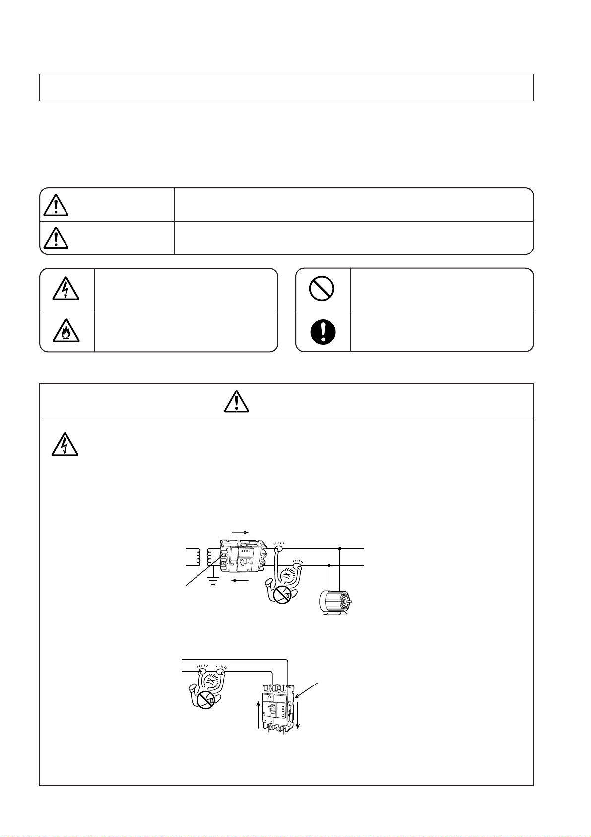
1.1 Cautionary instructions for operation ................................................................................................................................................................ 1
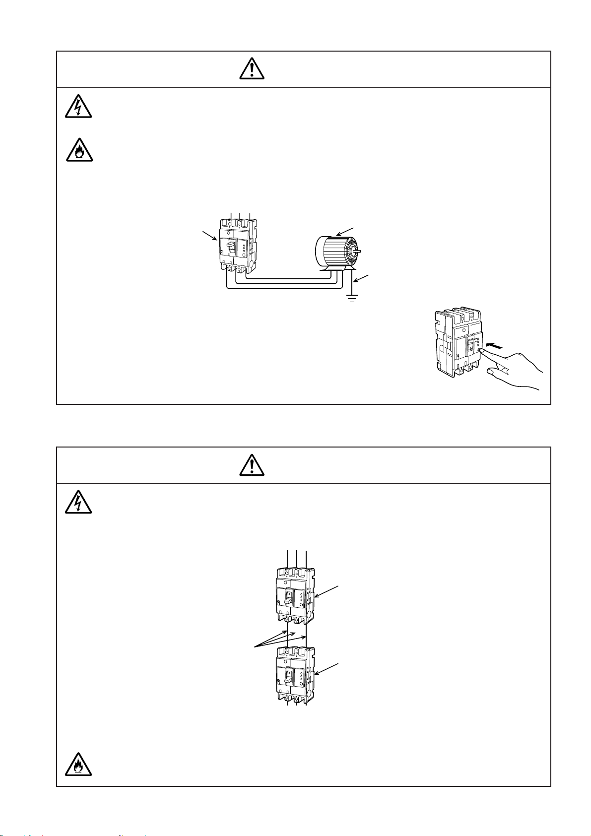
1.2 Cautionary instructions for maintenance & inspection .................................................................................................................................... 2
1.3 Cautionary instructions for work ........................................................................................................................................................................3
2. Before using
2.1 Cautionary instructions in general .....................................................................................................................................................................5
2.2 Operation ...............................................................................................................................................................................................................6
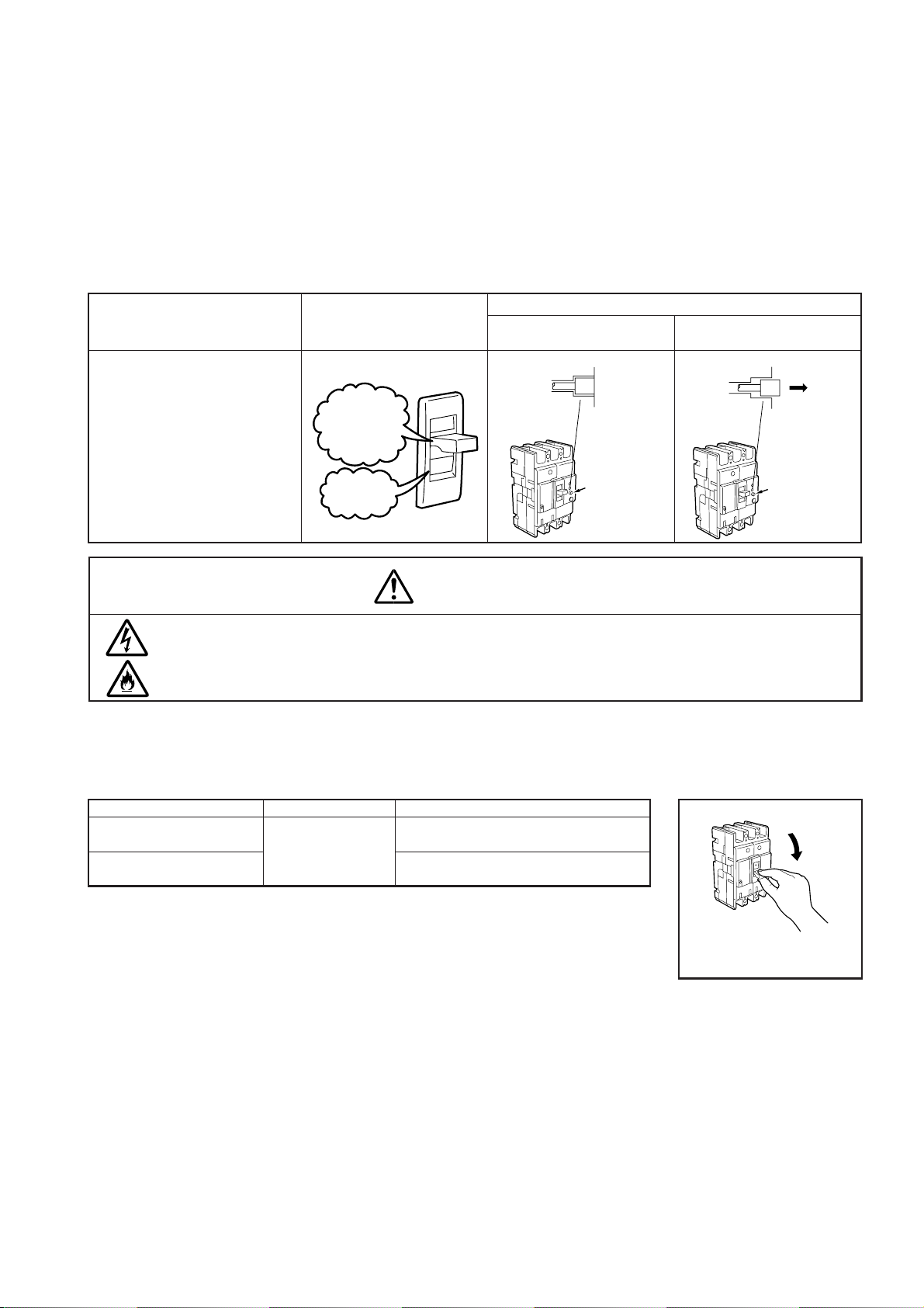
2.2.1 Switching operation ......................................................................................................................................................................................... 6
2.2.2 Trip and reset operation ..................................................................................................................................................................................7
2.3 How to set current rating, trip characteristic, sensitive current and operating time .................................................................................. 10
2.3.1 Cautionary instructions for setting .............................................................................................................................................................. 10
2.3.2 How to set characteristics of molded-case circuit breakers [electronic overcurrent tripping type] ..................................................... 10
2.3.3 How to set characteristics of molded-case circuit breakers [electronic overcurrent tripping type] ..................................................... 12
2.3.4 How to set characteristics of molded-case circuit breakers [Applicable models: NFE2000-S, NFE3000-S, NFE4000-S] .................... 12
2.3.5 How to set inverse time-delay or instantaneous tripping characteristics of circuit breakers
[Adjustable thermal or magnetic type] ........................................................................................................................................................ 13
2.3.6 How to switch voltage, sensitivity current and operating time (time delay type) of earth leakage circuit breakers ........................... 13
2.3.7 How to change rated current, tripping characteristic and leak tripping characteristic series earth leakage
circuit breakers (electronic overcurrent tripping type) .............................................................................................................................. 14
2.3.8 How to switch voltage, sensitivity current and operating time of earth-leakage relay .......................................................................... 16
3. Installation
3.1 Notice for selection ............................................................................................................................................................................................17
3.2 Normal service conditions .................................................................................................................................................................................17
3.3 Non-standard conditions ...................................................................................................................................................................................18
3.4 Inspection at arrival ............................................................................................................................................................................................19
3.5 Conditions during transport and storage ........................................................................................................................................................ 19
3.5.1 Transport ........................................................................................................................................................................................................ 19
3.5.2 Storage ............................................................................................................................................................................................................19
3.6 Installation and connection ...............................................................................................................................................................................20
3.6.1 General ............................................................................................................................................................................................................20
3.6.2 Installation ......................................................................................................................................................................................................20
3.6.3 Connection ......................................................................................................................................................................................................21
3.6.4 Mounting direction ......................................................................................................................................................................................... 22
3.6.5 Distances between circuit breaker and earthed metal parts ...................................................................................................................... 23
3.6.6 Current-carrying capacity and operating temperature ............................................................................................................................... 24
3.6.7 Breaker arrangements ...................................................................................................................................................................................26
3.6.8 Instruction for connections .......................................................................................................................................................................... 32
3.6.9 Instruction for accessories .......................................................................................................................................................................... 41
3.6.10 External accessories ..................................................................................................................................................................................... 53
4. Maintenance and inspection
4.1 Initial inspection ................................................................................................................................................................................................ 73
4.2 Periodical inspection ..........................................................................................................................................................................................77
4.3 Inspection after tripping .................................................................................................................................................................................... 77
4.4 Yardstick service life ..........................................................................................................................................................................................78
4.5 Standard tools and measuring instruments .................................................................................................................................................... 78
5. Troubleshooting
5.1 Troubleshooting for circuit-breaker proper (MCCB/ELCB) ........................................................................................................................... 79
5.2 Troubleshooting for leakage operation portion .............................................................................................................................................. 80
5.3 Troubleshooting of accessories ........................................................................................................................................................................ 80
5.4 Analysis of unnecessary operation ................................................................................................................................................................. 81
5.4.1 Classification of ELCB operation ................................................................................................................................................................ 81
5.4.2 Detail of operation ..........................................................................................................................................................................................81
6. After-sales service
6.1 Countermeasures to be taken in case of anomaly .......................................................................................................................................... 85
6.2 After-sales service system ................................................................................................................................................................................85
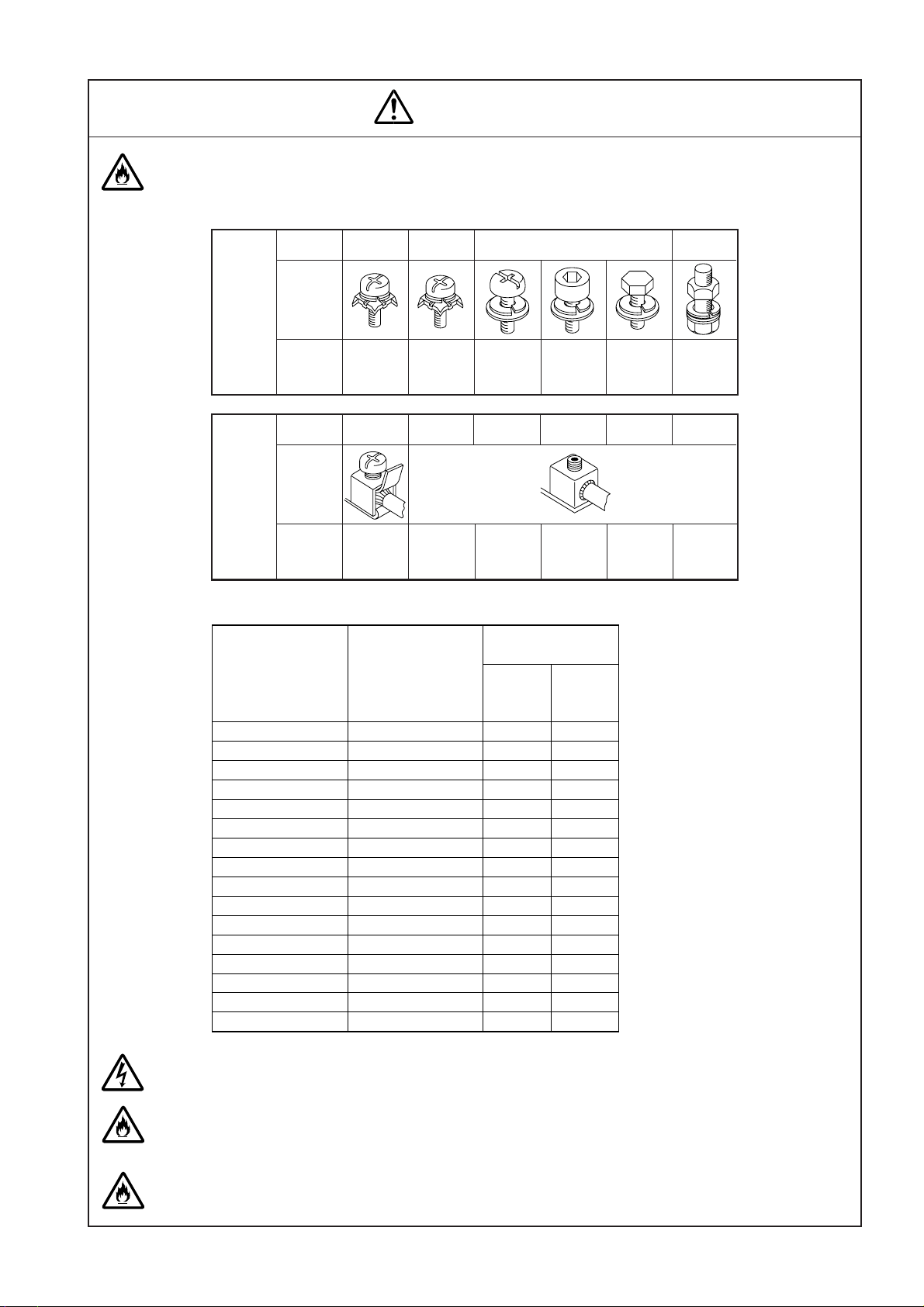
APPENDIX 1 Breaker mounting screws .......................................................................................................................................................................... 86
APPENDIX 2 Standard tightening torque for connections ............................................................................................................................................ 87
APPENDIX 3 Operating force of handle .......................................................................................................................................................................... 88
APPENDIX 4 Service network ...........................................................................................................................................................................................89

1. Items to be practiced without fail for safety
For correct operation, please go over this paper “Items to be practiced without fail for safety” beforehand.
●Essential items to ensure safety are stated here. Be sure to follow the cautionary instructions given
below.
●The manufacturers assembling their products using this breaker are requested to convey the require-
ments stated in this section “Items to be practiced without fail for safety” to the end users.
●The marks used respectively mean the following.
Wrong handling can cause dangerous situation in which possibility of fatal
accidents or serious injuries is assumed.
Wrong handling can cause dangerous situation in which possibility of signifi-
cant or minor injuries or only impersonal damages is assumed.
Warning for possible electrification
under certain conditions.
Warning for possible outbreak of a
fire under certain conditions.
This means prohibition. Never ignore
this indication.
Be sure to follow these instructions
without fail.
1.1 Cautionary instructions for operation
DANGER
CAUTION
●Don’t touch the terminal. Electrification can result.
●The earth leakage circuit breaker is so composed to operate when differential current be-
tween going and returning reaches certain level, and no leakage is detected in the case as
illustrated below. Never touch, therefore, the uncovered charged parts, two places at a time,
and the power source side of the earth leakage circuit breaker.
The circuit breaker doesn’t operate at the electrification.
1
DANGER
Line side
Load side
Earth leakage circuit breaker
Earth leakage
circuit breaker
Going current
Going current
Return current
Return current
[When uncovered charged parts are touched at two places]
[When the power source side of the breaker is touched]
ON
ON

●Layman’s work is dangerous. Any electric work must be carried out by a qualified person
(electrician).
●When the breaker cuts off automatically, turn it on after eliminating the cause. Otherwise,
electrification and fire can result.
If the cause is unknown, please contact us at our service station, branch offices, local offices,
or ask an electrician in your country.
●Be sure to earth all the electrical devices of the circuits in which the earth leakage circuit
breaker is used.
●Check operation of the earth leakage circuit breaker once a month
or so by pressing the test button.
The breaker is out of order if it isn’t turned to “OFF” or “TRIP.”
Please get in touch with us at our service stations, branch offices,
local offices, or ask an electrician in your country.
●Maintenance and inspection must be practiced by a specialist having electrical knowledge.
●Before maintenance & inspection, turn off the upper circuit breaker and make sure of no
current conducting to avoid possible electrification.
●Retighten the terminals regularly according to the
inspection manual. Otherwise, fire can take place.
1.2 Cautionary instructions for maintenance & inspection
2
CAUTION
CAUTION
5.2 Periodical inspection
As for fastening torque, refer to
Appendix 2.
()
ON
Earth leakage circuit breaker Electric device (including household
electric appliance)
Grounding work
ON
Procedure 1: Upper circuit breaker
(Turn OFF)
Objective circuit breaker for
maintenance & inspection
Procedure 2: With a detector, make
sure of no current conducting.
OFF
OFF

3
●Any electric work must be carried out by a qualified person (electrician).
●Before wiring, turn off the upper circuit breaker and make sure of no current conducting.
Electrification can result.
●Earth leakage circuit breaker dedicated to single phase 3-wire and three phase 4-wire types,
be sure to connect the neutral wire to the neutral phase. Open phase or overcurrent fails
operation and causes fire.
For 1φ, 3-W, connect the neutral wire to neutral
pole
When used for single phase, 3-wire type, connect
the neutral wire to the neutral pole of the earth
leakage circuit breaker.
For 3φ, 4-W, connect the neutral wire to neutral
pole
●Connect the earth leakage circuit breaker to the power source suitable for the ratings of the
breakers. Connecting to a wrong power can cause malfunction and failure.
1.3 Cautionary instructions for work
CAUTION
Procedure 1: Upper circuit breaker
(Turn OFF)
Objective circuit breaker
Procedure 2: (With a detector, make sure
of no current conducting.)
OFF
OFF
OFF
240V 120V
120V
The neutral wire
The neutral wire
The neutral pole
OFF

●At wire connection, fasten the terminal screws with the torque stated in the instruction manual.
Fastening with incorrect torque can cause fire.
4
CAUTION
Terminal
screw
Screw
diameter M5
Shape
M8 M12
M6
Fastening
torque
N·m
2~3 2.5~4.0 5.0~7.0 8.0~13.0 8.0~13.0 40.0~50.0
30.0~40.0
Solderless
terminal
screw
Screw
diameter M6
Shape
M10
Fastening
torque
N·m
4.0~6.0 3.5~4.5 20.0~30.0 30.0~40.0 50.0~60.0
M16 M18 M20 M24
●Refrain from installing in abnormal environment such as high temperature, high humidity,
high dust content, corrosive gas ambient, or of excessive vibration or impact. Electrification,
fire, or operation failure can result.
●Carry out the work avoiding foreign matters such as dust, concrete powder, steel chips, and
rain water to enter into the equipment. Otherwise, operation failure can result.
Example of front connection type fastening torque (Others are in Appendix 2.)
Size of conductor,
AWG or kcmll(mm
2
)
Tightening torque
[N·m]
14(2.1)
12(3.3)
10(5.3)
8(8.4)
6(13.3)
4(21.2)
3(26.7)
2(33.6)
1(42.4)
1/0(53.5)
2/0(67.4)
3/0(85.0)
4/0(107)
250(127)
300(152)
350(177)
Size of conductor,
IEC(mm
2
)
2.5
4.0
6.0
10
16
25
35
–
50
–
70
95
–
120
150
185
4
4
4
4.5
5.1
5.1
6.5
6.5
6.5
6.5
6.5
ー
ー
ー
ー
ー
5
5
5
13
13
13
13
13
13
13
13
25.5
25.5
25.5
25.5
25.5
NF125-CW
NF125-SW
NF125-HW
NV125-CW
NV125-SW
NV125-HW
NV125-RW
NF125-SGW
NF125-HGW
NF125-RGW
NF125-UGW
NF160-SGW
NF160-HGW
NF250-SGW
NF250-HGW
NF250-RGW
NF250-UGW
Tightening torque for Solderless terminal

2. Before using
Besides operation, the items in this section are also applicable to work, maintenance and inspection.
2.1 Cautionary instructions in general
5
(1) Refrain from touching the terminal unit as electrification can result.
Note: Besides the terminal of the circuit breaker, the terminal unit includes the wires, bus
bars, ring-type terminals, and other wiring materials.
(1) Layman’s work is dangerous. Any electrical work must be carried out by a qualified person
(electrician).
(2) Be sure to earth all the electrical devices of the circuits in which the earth leakage circuit
breaker is used.
(3) Check operation of the earth leakage circuit breaker once
a month or so by pressing the test button.
The breaker is out of order if it isn’t turned “OFF” or “TRIP”.
Please contact us at our service stations, branch offices,
local offices, or ask an electrician in your country.
CAUTION
DANGER
ON
Earth leakage circuit breaker Electrical equipment
(including household appliances)
Grounding work
ON

6
2.2 Operation
2.2.1 Switching operation
Electric power can be turned ON/OFF by moving the handle up/down.
Note 1. Never apply any excessive impact to the handle.
Note 2. When the extension handle is used, fix it firmly with screws. After use, remove the extension
handle quickly.
Note 3. ON, OFF operation must operate quickly and correctly. Otherwise it may cause open phase
with a few time when operated slowly in case of some types of breakers.
Operating method and condition of the circuit breaker are illustrated below.
11
11
1Closing (ON)
Switch on the
power (closing)
ON operation ON state indication
Moving the handle upward closes
the circuit.
22
22
2Opening (OFF)
Switch off the
power (opening)
OFF operation OFF state indication
Moving the handle downward opens
the circuit.
ON
ON
A white
line
appears.
ON
mark appears
on red back-
ground.
OFF
OFF
OFF mark
appears on
green
background.

2.2.2 Trip and reset operation
(1) For moulded-case circuit breaker
11
11
1Tripping
The moulded-case circuit breaker has an overcurrent tripping device which opens the circuit on
detecting magnitude of overload current or short-circuit current, and is used for protecting electric
wires and other power circuit.
Automatic opening (breaking) of circuits in this way is called “tripping.”
For some products, the circuit breakers can be tripped mechanically from the outside by pressing
the trip button provided on the cover.
Press the trip button while the circuit breakers is kept “ON.” When in “OFF” state, tripping is not
made in some cases.
There are two kinds of trip indications as shown below.
Type Trip indication Re-closing method
Moulded-case circuit breaker in general NF,
NFE, MB, BH.
Eliminate the cause of tripping
Reset operation
Re-closing
At an automatic breaking, eliminate the cause then switch on the breaker. Otherwise fire can
be resulted.
If the cause isn’t known, contact us at our service stations, branch offices, local offices, or ask
an electrician in your country.
22
22
2Reset operation
In the case of (1)-(b) of above (1), re-closing is possible by resetting.
Resetting Reset check
When hands are released after reset, the
handle turns to either mode shown below.
Turns OFF.
(reset completion)
Returns to trip
(not completion)
Repeat resetting
once more.
Pull down the handle forcefully in OFF direc-
tion.
Tripped state
7
CAUTION
OFF
ON
Trip
The handle
shows the
mid-position
between ON
and OFF.
No white
line is seen.
OFF
ON
OFF
OFF
OFF mark
appears on
green
background.
OFF
ON
Trip
The handle
shows the
mid-position
between ON
and OFF.
No white
line is seen.

Automatically reset when the handle is turned
to ON position.
NV30-CS·50-CSA
NV63-CW~600-CW
NV32-SW~1200-SB
Type Leakage indicator reset
(2) For earth leakage circuit breaker
11
11
1Trip
Tripping of earth leakage circuit breaker includes two kinds; leak trip in which magnitude of leakage
is detected for automatic tripping (open circuit), and overcurrent trip in which magnitude of overload
current or short-circuit current is detected for automatic tripping.
For distinction of two kinds of tripping, the leak indication button comes out at leak trip only. The
indication button also comes out when the leak test button is pushed for checking leak current
operation.
Type Handle indication
Leakage indication button
Overcurrent trip or tripping by
trip button
Leakage trip; tripping by
leakage test button
NV, MN
When the breaker cuts off automatically, turn ON the handle after eliminating the cause.
Otherwise, electrification and fire can take place.
If the cause isn’t known, contact us at our service stations, branch offices, local offices, or ask
an electrician in your country.
22
22
2Reset operation
When the leakage indication button comes out, remove the cause of failure, reset in the following
procedure, then close the circuit again.
Handle reset
Push down forcefully the
handle in OFF direction. Automatically reest when the handle is reset.
Reset the handle.
8
CAUTION
OFF
ON
Trip
The handle
indicates
middle position
of ON and
OFF.
No white
line is seen.
OFF
ON
Not come-out
Leakage indication
button (white)
Come-out
Leakage indication
button (white)
OFF
ON
OFF

Push in the reset button by a finger.
9
(3) For earth leakage relay
11
11
1Operation
When leakage is detected by the earth leakage relay, contact point output is given, the leakage
indicator button comes out, or the leakage indication lamp glows.
22
22
2Reset operation
When the leakage indication button comes out or the leakage indication lamp glows, remove
the cause then reset before starting operation again. Otherwise, electrification can result.
If the cause isn’t known, contact us at our service stations, branch offices, local offices, or ask
an electrician in your country.
(4) Circuit protector
11
11
1Trip
The handle turns off at tripping.
Note: Where an alarm switch is attached, the handle stops between ON and OFF positions.
22
22
2Reset
Eliminate the cause of tripping, then close. (Resetting isn’t necessary as the circuit protector is
reset automatically.)
Note: When an alarm switch is attached, move the handle to OFF side once, then to ON side for
reclosing. (The alarm switch of CP30-BA is reset at ON operation.)
Type
NV-ZSA, NV-ZLA
NV- ZU, NV-ZBA
NV-ZHA
Handle reset
—
—
Leakage indicator reset
Push to the projected reset button for leakage indicator.
Pushing the reset button turns off the leak indication
lamp and resets. Turning off the control power also re-
sets automatically.
CAUTION

10
2.3 How to set current rating, trip characteristic, sensitive current and oper-
ating time
2.3.1 Cautionary instructions for setting
●Let a person having technical knowledge of electricity set the breaker.
●Before setting, turn off the upper circuit breaker, or turn off the circuit breaker to be set or trip
the breaker, then make sure of no current conducting.
Otherwise, electrification can result.
2.3.2 How to set characteristics of molded-case circuit breakers [electronic overcurrent
tripping type]
Applicable
model
Layout of
setting dials
Group A Group B
NF125-SGW(RE), NF125-HGW(RE), NF160-SGW(RE)
NF160-HGW(RE), NF250-SGW(RE), NF250-HGW(RE)
NF400-SEW, NF400-HEW, NF400-REW, NF400-UEW
NF630-SEW, NF630-HEW, NF630-REW, NF800-CEW,
NF800-SEW, NF800-HEW, NF800-REW, NF800-UEW
NF1000-SEW, NF1250-SEW, NF1600-SEW
CAUTION
Procedure 1: Turn off the upper
circuit breaker.
Circuit breaker to be set
Procedure 2: With a detector, make
sure of no current conducting.
OFF
OFF
Connection cover
Tr i p
(PTT)
button
70% LED (green)
PAL LED (yellow)
OVER LED (red)
Setting dial
Replacement label
Rated current label
Cover
Settingdial
OVERLED(red)
70%LED(green)
PALLED(yellow)
Buttoncover
Trip(PTT)
button
S
E
A
L
E
D
S
E
A
L
E
D
S
E
A
L
E
D
S
E
A
L
E
D

11
(1) Open the button cover using a
screwdriver as illustrated at left.
(2) Set operating characteristics by
turning the dials.
For turning the dials for chracteristic
setting,use a screwdriver as illus-
trated at left.a
1A slotted head screwdriver of
3mm width and 0.5mm thick-
ness at the top is suitable for the
setting.
2At setting,refrain from applying
force more than necessary as
such can cause broken.
(Adequate operation torque is
0.02N·m maximum.)
* As for Is and Ip setting,a set
value may advance to the next
one in some cases
3Except for the dials of current
setting Ir and instantaneous
pick up current Ir keep the ar-
row of the setting dials within the
range of the thick line of setting
value.
4On 4P circuit breakers, neutral
protection is selected using a 2-
position setting:
4P 3E (neutral unprotected),
4P 4E (neutral protection at Ir),
where Ir is the circuit breaker
current setting.
(3) Close the button cover.
Setting
method [for Group B]
[for Group A]
Fastening torque
0.3~0.6N·m
Forsetting,turn
thearrowofeach
dialtotheposition
desired
Stepsettingtype:
LTDtimeT
L
,
STDpickupcurrentI
S
,
STDtimeT
S
,
Pre-alarmpickupcurrentI
P
Continuouslyadjustabletype:
CurrentsettingIr
InstantaneouspickupcurrentI
i
LTDtimeTL
Note1) Pre-alarmpickup
currentI
P
STDtimeT
S
Instantaneouspickup
currentI
i
Current
settingIr STDpickup
currentI
S
NeutralprotectionI
Np
I
i
(×250A)
Is
(×Ir)
Ts
(s)
Ip
(×Ir)
T
L(s)
Ir
(A)
Ip
(×Ir)
.95
.9
.85
.8
1.0.7
4P3E 4P4E
I
N
p
70% PAL OVER
IT
.75
50/60Hz(AConly)
.06
.1 .2
.312
60 80
100
TEST
MODEL
150
125
175 200
225
250
6
4
8
12
10
14
2.5
2
5
4
3
3.5 7
6
8
10
.95
.9
.85
.75
.8
1.0.7
A
250RE250 In
70% PAL OVER
Ts
Is
Ii
T
I
TL
Ir
Ip
(1) Open the transparent cover.
(2) Set tripping characteristics by turn-
ing the dials.
For turning the dials for character-
istic setting, use a screwdriver as
illustrated at left.
1A slotted head screwdriver of
4.5mm width and 0.6 mm thick-
ness at the top is suitable for the
setting.
2At setting, refrain from applying
force more than necessary as
such can cause failures.
(Adequate operation torque is
0.05N·m maximum.)
3Except for the dials of current
setting lr and instantaneous trip-
ping current ll, keep the arrow
of the setting dials within the
range of the thick line of setting
value.
Stopping the arrow in the middle
may advance the set value to
the next one in some cases.
* As for Is setting, a set value
may advance to the next one
in some cases.
(3) Take the seal of the same value for
setting value out of the replacement
labels, and stick the label to the top
of the handle.
(4) Close the transparent cover.
For setting, turn
the arrow of each
dial to the scale
position desired
Step setting type:
Rated current In
Long time-delay operating time T
L
Short time-delay tripping current I
S
Short time-delay operating time T
S
Pre-alarm current I
P
Continuously adjustable type:
Current setting Ir (Note 1)
Instantaneous trip current I
I
Rated
current
Current
setting
Long time-delay
operating time
Short time-delay
tripping current
Instantaneous
tripping current
Pre-alarm
current
Short time-delay
operating time
4567
8
10 4
6
810
12
14
16
3
2
100
.06 .3
.1 .2
.7
.8 .9
1.0
60
12
150
300
350
250
225
200
In(A)
TEST
T
L
(s) T
S
(s) I
P
(×In, Ir)
I
S
(×In, Ir) I
I
(×400A)
.5
.7 .8
1
I
r
(×400A)

12
2.3.3 How to set characteristics of molded-case circuit breakers [electronic overcurrent
tripping type]
Applicable model
Item
Layout of
setting
terminals
Setting method
ETR (Electronic trip relay) mounting circuit breaker
(NF1250-UR)
Rated current Short time-delay tripping characteristic
(1) Take off the seal, loosen the cover set screw and
take off the cover.
(2) Loosen the rated current switching screw, move it
to the position desired for setting by fingers, and
tighten it with 0.3 to 0.45 N·m torque.
A slotted head screwdriver of 4.5mm width and
0.6mm thickness at the top is suitable for the set-
ting.
(3) Take the label and the seal of the same value for
setting value out of the replacement labels.
(4) Change the rated current label at the top end of
the handle.
(5) Attach the cover, and stick the seal.
(1) Remove the seal, loosen the cover set screw, and
take off the cover.
(2) Loosen the short limit pickup current switching
screw, move it to the desired setting positon by
fingers, and tighten it with 0.3 to 0.45 N·m torque.
A slotted head screwdriver of 4.5mm width and
0.6mm thickness at the top is suitable for the set-
ting.
(3) Take the seal out of the replacement labels.
(4) Attach the cover and stick the seal.
2.3.4 How to set characteristics of molded-case circuit breakers [Applicable models:
NFE2000-S, NFE3000-S, NFE4000-S]
Remarks: For the electronic circuits of circuit breaker, control power is supplied from the built-in current transformer.
Accordingly, the breakers can be used with no regard to circuit voltage.
Rated current label
Rated current switching screw
Seal
Cover
Electronic type
trip relay unit
(with cover)
Cover set screw
(Lower side of seal)
Replacement labels
(Rated current, seal)
Short time-delay pickup current
switching screw
Scale setting method
PUSH TO TRIP
(Trip button)
The button is for
mechanically tripping.
Use the trip button for
sequence check only
and refrain from using
it for ordinary open
circuit operation.
Ampere rating
(Rated current adjustable dial)
Set at any rated current desired
SHORT-DERAY PICK UP
(Short time-delay tripping adjustable dial)
Set at a desired short limit trip characteristic.
TEST TERMINAL
Refrain from using this
terminal normally as it is
for checking tripping
characteristic using the
tester offered separately.
PUSH TO TRIP
INSTANTANEOUS PICK UP
CURRENT 30000A (FIXED)
TEST TERMINAL
1600
2000
1200
MED
MIN. MAX.
AMPERE
RATING
SHORT-DELAY
PICK UP

13
2.3.5
How to set inverse time-delay or instantaneous tripping characteristics of circuit breakers [Adjustable thermal or magnetic type]
Applicable model
Item
Layout of
setting
terminals
Setting
method
Adjustable magnetic type
NF125-SGW(RT), NF125-HGW(RT), NF160-SGW(RT), NF160-HGW(RT), NF250-SGW(RT), NF250-
HGW(RT), NF630-SW, NF800-SDW, NF1000-SDW, NF1250-SDW, NF1600-SDW, NF2000-S, NF2500-S
NF3200-S, NF4000-S, NV630-SW, NV1000-SB, NV1200-SB, NF-SJW, NF-HJW
Inverse time-delay or instantaneous tripping characteristic
Inverse time-delay oparation or instantaneous pickup current can be adjusted simply by turning the switching screw.
For setting current of each notch, please refer to the operation characteristic curve.
Note 1. Trip current differs at middle position of the scale.
Note 2. Turn the adjust button in arrow direction only.
Note 3. A slotted head screwdriver of 1mm thickness at the top is suitable for the setting.
2.3.6
How to switch voltage, sensitivity current and operating time (time delay type) of earth leakage circuit breakers
Applicable model
Setting
terminal
arrangement
Voltage
selection
Sensitivity,
operating time
NV63-CW, NV125-CW, NV250-CW,
NV32-SW, NV63-SW, NV125-SW, NV250-SW
NV63-HW, NV125-HW, NV250-HW
NV125-RW, NV250-RW
NV400-CW, NV400-SW, NV630-CW, NV630-SW
Multi voltage, sensitivity switching in 3 steps Dual voltage, sensitivity switching in 2 steps
NV1000-SB, NV1200-SB
Multi voltage types can be used for three circuit volt-
ages as it is.
Dual voltage type can be used for two circuit voltages
as it is.
• A slotted head screwdriver of 4.5mm width and
0.6mm thickness at the top is suitable for setting.
• Stopping between two set values makes sensitivity
current or operating time unstable in some cases.
Be sure to set at the position of each set value.
• Refrain from applying unnecessary force at the time
of setting.
It can cause failure.
(Addequate operation torque is 0.05N·m max.)
The sensitivity selector is attached to the right side of the cover
viewed from the front side.
To change from 500mA to 200mA, take the procedure state below
while referring to the illustration given above.
(1) Loosen the cover screw and take off the cover.
(2) Loosen the switching screw and move it to the left.
*Turn 5 to 6 times with a screwdriver suitable for the groove
width.
(3) Fasten the switching screw.
Tighten the screw firmly as the bottom is to be connected elec-
trically. Cover tightening torque: 0.4 to 0.6N·m
A slotted head screwdriver of 6mm width and 0.8mm thick-
ness at the top is suitable for setting.
(4) Set the cover back in place and fix with the screw.
*For the time delay type of the above model, switching proce-
dure of operating time is the same as that of current switching.
Inverse time-delay oparation or
instantaneous pickup current
switching screw Set at the position effective
for fixing
Set at the position effective for fixing
Sensitivity
selector
Operation
time switch
(time delay type)
Leakage
indication
button
Trip button
Test button
For setting, turn the
arrow mark on the
screw in the direction
of a desired scale
position.
Operation time
(time delay type)
Sensitivity
Arrangement
Cover (front)
200mA
Cover (rear)
500mA
Switching screw
Cover screw
Control

14
2.3.7 How to change rated current, tripping characteristic and leak tripping characteristic of
earth leakage circuit breakers (electronic overcurrent tripping type)
Applicable model
Setting dial arrangement
Tripping characteristics setting method
Setting method of leak tripping characteristics
(sensitivity current, operation time)
NV100-SEP, NV100-HEP
NV250-SEW, NV250-HEW
(1) Take off the seal, if sticked.
(2) Loosen the cover screw and open the cover.
(3) Set tripping characteristics by turning the dials.
For turning the dials for characteristic setting,
use a screwdriver as illustrated at left.
1A slotted head screwdriver of 3 mm width
and 0.5 mm thickness at the top is suitable
for the setting
2At setting, refrain from applying force more
than necessary as such can cause failures.
(Adequate operation torque is 0.02N·m
maximum.)
3Except for the dials of current setting lr and
instantaneous tripping current li, keep the
arrow of the setting dials within the range of
the thick line of setting value.
Stopping the arrow in the middle may ad-
vance the set value to the next one in some
cases.
* As for Is setting, a set value may advance
to the next one in some cases.
(4) The blank labels may be used for indication of
the current setting Ir. Please fill in the blank la-
bel with oily ink, and stick the label to the posi-
tion under the handle.
(5) Close the cover and fasten the screws.
(6) Stick the seal, if it is necessary.
• For setting sensitivity current and operation time, open the cover in the
same procedure as for tripping characteristic setting.
• A slotted head screwdriver of 4.5mm width and 0.6mm thickness is
suitable for the setting.
• Stopping in the middle of each set values makes sensitivity current or
operating time unstable in some cases.
Be sure to set exactly at the position of each set value.
• At setting refrain from applying force more than necessary as such can
cause failures.
(Adequate operation torque is 0.05N·m maximum.)
Seal attaching
position
OVER LED (Red)
PAL LED (Yellow)
70% LED (Green)
Sensitivity current setting dial
Rated current label
Test cover
Operation time setting dial
(for time delay type)
Leakage indicator
(comes out at leak tripping)
Tr ip (PTT) button
Replacement
label
Test button
Setting dial
SEALED
200
175
150
125 225
80
210.06 . 3
. 1 . 2
. 7
. 8 . 9
1. 0
3
4567
8
60
12 100
Ir (A) T
L
(S) T
S
(S)I
S
(×Ir) I
i
(×225A) I
P
(×Ir)
Cover screw
Dial
Current
setting
Step setting type:
Long time-delay operating time T
L
Short time-delay tripping current IS
Short time-delay operating time TS
Pre-alarm current IP
Continuously adjustable type:
Current setting Ir
Instantaneous trip current Ii
Long time-delay
operating time Short time-delay
operating time
Short time-delay
tripping current
Instantaneous
tripping current
Fastening torque
0.9~1.2N•m
Pre-alarm
current
For setting, turn
the arrow of each
dial to the scale po-
sition desired
6
10
812
16
4
For setting, turn the arrow of each
dial to the scale position desired.

For setting, turn the arrow
of each dial to the scale
position desired.
15
Applicable model
Setting dial arrangement
Tripping characteristics setting method
Setting method of leak tripping characteristics
(sensitivity current, operation time)
NV400-SEW, NV400-HEW, NV400-REW
NV630-SEW, NV630-HEW
NV800-SEW, NV800-HEW
(1) Open the transparent cover.
(2) Set tripping characteristics by turning the dials.
For turning the dials for characteristic setting,
use a screwdriver as illustrated at left.
1A slotted head screwdriver of 4.5mm width
and 0.6 mm thickness at the top is suitable
for the setting.
2At setting, refrain from applying force more
than necessary as such can cause failures.
(Adequate operation torque is 0.05N·m
maximum.)
3Except for the dials of current setting lr and
instantaneous tripping current ll, keep the
arrow of the setting dials within the range of
the thick line of setting value.
Stopping the arrow in the middle may ad-
vance the set value to the next one in some
cases.
* As for Is setting, a set value may advance
to the next one in some cases.
(3) Take the seal of the same value for setting value
out of the replacement labels, and stick the la-
bel to the top of the handle.
(4) Close the transparent cover.
• For setting sensitivity current and operation time, open the cover in the
same procedure as for tripping characteristic setting.
• A slotted head screwdriver of 4.5mm width and 0.6mm thickness is
suitable for the setting.
• Stopping in the middle of each set values makes sensitivity current or
operating time unstable in some cases.
Be sure to set exactly at the position of each set value.
• At setting refrain from applying force more than necessary as such can
cause failures.
(Adequate operation torque is 0.05N·m maximum.)
OVER LED (Red)
PAL LED (Yellow)
70% LED (Green)
Sensitivity current setting dial
Rated current label
Connector
cover
Operation time setting dial
(for time delay type)
Leakage indicator
(comes out at leak tripping)
Tr ip button
(PTT)
Transparent cover
Replacement label
Test button
Setting dial
For setting, turn
the arrow of each
dial to the scale
position desired
Step setting type:
Rated current In
Long time-delay operating time TL
Short time-delay tripping current IS
Short time-delay operating time TS
Pre-alarm current IP
Continuously adjustable type:
Current setting Ir (Note 1)
Instantaneous trip current II
Note 1.
Current setting Ir becomes effective
when rated current In is set as maximum.
Rated
current
Current
setting
Long time-delay
operating time
Short time-delay
tripping current
Instantaneous
tripping current
Pre-alarm
current
Short time-delay
operating time
4567
8
10 4
6
810
12
14
16
3
2
100
.06 .3
.1 .2
.7
.8 .9
1.0
60
12
150
300
350
250
225
200
In(A)
TEST
T
L
(s) T
S
(s) I
P
(×In, Ir)
I
S
(×In, Ir) I
I
(×400A)
.5
.7 .8
1
I
r
(×400A)

16
2.3.8
How to switch voltage, sensitivity current and operating time of earth-leakage relay
Applicable
model
Switching terminal arrangment
Voltage selection
ZBA
• When source voltage is 120V in the above
drawing,connect to 4 and 5 terminals.
• When source voltage is 240V in the above
drawing,connect to 4 and 6 terminals.
Earth leakage relay
Sensitivity,operation time
• As lotted head screwdriver of 4.5mm width
at the top and 0.6mm thickness is suitable
for setting.
• Stopping between two set values makes
sensitivity current or operating time un-
stable in some cases.
Be sure to set at the position of each set
value.
• Refrain from applying unnecessary force
at the time of setting.
It can cause failure.
(Adequate operation torque is 0.05N·m
max.)
ZCT ZCT
3421
415V
240V
ZCT
5
876910
COM OUT IN
a1 c1
Change-over
switch
0.2A
0.5A
1A
ZSA, ZHA, ZLA ZU
• When source voltage is 240V in the above
drawing,connect to 1 and 2 terminals.
• When source voltage is 415V in the above
drawing,connect to 1 and 3 terminals.
• As lotted head screwdriver of 4.5mm width
at the top and 0.6mm thickness is suitable
for setting.
• Stopping between two set values makes
sensitivity current or operating time un-
stable in some cases.
Be sure to set at the position of each set
value.
• Refrain from applying unnecessary force
at the time of setting.
It can cause failure.
(Adequate operation torque is 0.05N·m
max.)
• When source voltage is 240V in the above
drawing,connect to 6 and 7 terminals.
• When source voltage is 415V in the above
drawing,connect to 6 and 8 terminals.
•Turn the change-over switch with a screw-
driver to set the arrow at a desired scale
position.
ZCT
1
Sensitivity current
selector
Operating time
selector
(time-delay type)
3
456
240V
120V
789
abc
ZCT
12345
c1a1
c2b2a2
Sensitivity current
selector
Operating time
selector
(time-delay type)
240V
415V
768910

17
3. Installation
3.1 Notice for selection
For selection, refer to the catalog, technical data, specifications and other technical materials.
For any question concerning the selection method, please enquire us.
We are not responsible for any failure and damage caused by wrong selection.
3.2 Normal service conditions
Our circuit breakers of the standard specifications are to be used in the following standard conditions.
• Operating ambient temperature: –10 to 40°C (Average temperature for 24 hours, however, shall
not be higher than 35°C.)
• Relative humidity: 85% max. with no dewing
• Altitude: 2,000 m maximum
• Ambient of no excessive water or oil vapour, smoke, dust, salt content, corrosive substance, vibra-
tion, and impact
Expected service life (MTTF) under the above conditions is 15 years.
• Lowering ratio of operational current in special ambient temperature over 40°C.
50°C………0.9 times
60°C………0.7 times
Expected service life (MTTF) will be reduced compare with normal service conditions.
Note. The environment shall be free from any dewing or freezing.
• Refrain from installing in any unusual environment of high temperature, high humidity, dust,
corrosive gas, vibration and impact. Electrification, fire, and malfunction can result.
CAUTION

18
3.3 Non-standard conditions
When operated under different conditions from the normal service conditions, it is necessary to take
the following measures against the operating conditions.
Even with such measures taken, however, service life may become shorter in some cases.
Special environment Circuit breaker for
special environment Specifications Applicable model
MCCB ELCB
Low
tempera-
ture
High
tempera-
ture, high
humidity
Corrosive
gas, salt
content
Dust,
vapour
Freezing warehouse,
low temperature room
Chemical plant
Chemical plant, Oil
refining plant
Cement plant, spinning
mill, gravel pit
Enclosed circuit
breaker
Added corrosion
resistive circuit
breaker
Circuit breaker for
low temperature
Circuit breaker for
moisture-fungus
treatment
This breaker is so designed to enable
power supply, switching, and short cir-
cuit breaking at -40°C. The operating
characteristics change at low tempera-
ture as they are adjusted for the refer-
ence ambient temperatur.
(For storing, consider the use is pos-
sible up to -50°C at the lowest.)
• Moisture-fungus treatment of the 1st
kind
In addition to special surface
treatment and special materials,
corrosionproof treatment is applied.
• Moisture-fungus treatment of the 2nd
kind
Special surface treatment is applied
and special materials are used. In hu-
mid environment, insulation strength
and other electrical performances
tend to be lowered. The special sur-
face treatment and the special ma-
terials are used to avoid such dete-
rioration.
• In the environment containing much
corrosive gas (gas concentration
level up to the note *given below), it
is advisable to use MCCB of added
corrosion resistive specifications.
For the breakers of added
corrosionproof type, corrosionproof
plating is applied to the metal parts.
• Where concentration of corrosive gas
exceeds the level stated below, it is nec-
essary to use MCCB of added corro-
sion resistive type being enclosed in a
waterproof type enclosure or in any en-
closure of protective structure.
* Concentration of corrosive gas al-
lowed by the Safety and Health Stan-
dard:
(Ex.) H2S (10 ppm), HCI (5 ppm),
CI2(1 ppm), SO2(5 ppm),
NH3(25 ppm) - (Japan Industrial
Health Association, since 1973)
Where concentration of corrosive gas
is about 1/100 of the noted level and
H2S (0.01 ppm), the standard MCCB
can be used.
Expected service life (MTTF) will be
less than 15 years.
Enclosed circuit breaker of dustproof (type I) or waterproof (type W) is advis-
able for places where much dust or vapour is contained.
For installing circuit breakers in explosionproof enclosure, use non-ammonia
mould product.
• 1600 A frame of
S-series and
lower
• All models of C-
series
• Moisture-fungus
treatment of the
1st kind (Note 2)
Front connection,
rear connection,
and flush plate
type of S-series
and C-series of
2000A frame and
lower.
• Moisture-fungus
treatment of the
2nd kind
All models of S-
and C- series
(Note 2)
• Front connection,
rear connction,
and flush plate
type of series S
and C of 2000A
frame and smaller
(Note 2)
All models of S-
and C- series
(Note 2)
All models of S-
and C- series
All models of leak-
age relay (Mois-
ture-fungus treat-
ment of the 2nd
kind only)
–
Note 1. SHT and UVT of internal accessories are excluded.
2. Electronic types are excluded.
This manual suits for next models
19
Table of contents
Other Mitsubishi Electric Industrial Electrical manuals

Mitsubishi Electric
Mitsubishi Electric MV Series User manual

Mitsubishi Electric
Mitsubishi Electric NP180 Series User guide

Mitsubishi Electric
Mitsubishi Electric RV-FR Series User manual

Mitsubishi Electric
Mitsubishi Electric A1SJ71DN91 User manual

Mitsubishi Electric
Mitsubishi Electric NF400-SEW User manual
Popular Industrial Electrical manuals by other brands

Murata
Murata GRJ216R72A472KE01 Series Reference sheet

Murata
Murata GRM1885C1H132JA01 Series Reference sheet

Murata
Murata GRM1885C1H221JA01 Series Reference sheet

Murata
Murata GRM0335C1H3R4BA01 Series Reference sheet

Murata
Murata GRM216R71H222KA01 Series Reference sheet

Murata
Murata GRM0335C2A7R9DA01 Series Reference sheet