Herman Miller Locale Modular Electrical Installation instructions

Z
© 2015 Herman Miller, Inc. Zeeland, Michigan. Printed in the U.S.A.
TM Locale is among the trademarks of Herman Miller, Inc.
Illustrations and specifications are based on the latest product information available at the time of publication.
The right is reserved to make changes in design and specifications at any time, without notice, and also to discontinue products.
Part no. 1bc57y rev B.
1
YLocale™Modular Electrical Installation and Disassembly for
Recycling Instructions
Parts Included:
Modular Power Duplex
Power Block
Power Block Harness
#10-12 x 1/2”
Phillips Pan
Head Tapping
Screw
Modular Power Entry
A
D
B
C
E
Tools Needed:
Power Driver #2 Phillips Bit
Electrically interconnected units must be mechanically
interconnected.
WARNING
!
Modular Power Entry,
New York
Block-to-Block Jumper
F
G
BRE04.
BRE01.
BRE05.
BRE02.
BRE03.XX08
BRE03.XX04
Disconnect power before installation. Failure to do so can
cause electrical shock and personal injury.
WARNING
!
All electrical connections to building electrical sources
must be made by a qualified electrician according to
national, state and local electrical codes.
NOTICE

Z
© 2015 Herman Miller, Inc. Zeeland, Michigan. Printed in the U.S.A.
TM Locale is among the trademarks of Herman Miller, Inc.
Illustrations and specifications are based on the latest product information available at the time of publication.
The right is reserved to make changes in design and specifications at any time, without notice, and also to discontinue products.
Part no. 1bc57y rev B.
2
1. Position Power Block (B)
or Power Block Harness (C)
onto Base Frame.
2. Secure to Frame with Pan
Head Screws (D).
3. Locate mounting holes
for mounting Modular Power
Duplex (A).
A
B
D
D

Z
© 2015 Herman Miller, Inc. Zeeland, Michigan. Printed in the U.S.A.
TM Locale is among the trademarks of Herman Miller, Inc.
Illustrations and specifications are based on the latest product information available at the time of publication.
The right is reserved to make changes in design and specifications at any time, without notice, and also to discontinue products.
Part no. 1bc57y rev B.
3
4. Secure Modular Power
Duplex (A) to inside wall
of Base with 4 Pan Head
screws (D).
5. Insert end of Modular Power
Duplex into Power Block.
Make sure connection fully
engages.
6. Feed End of Modular Power
Entry (E) through opening
in side of Base.
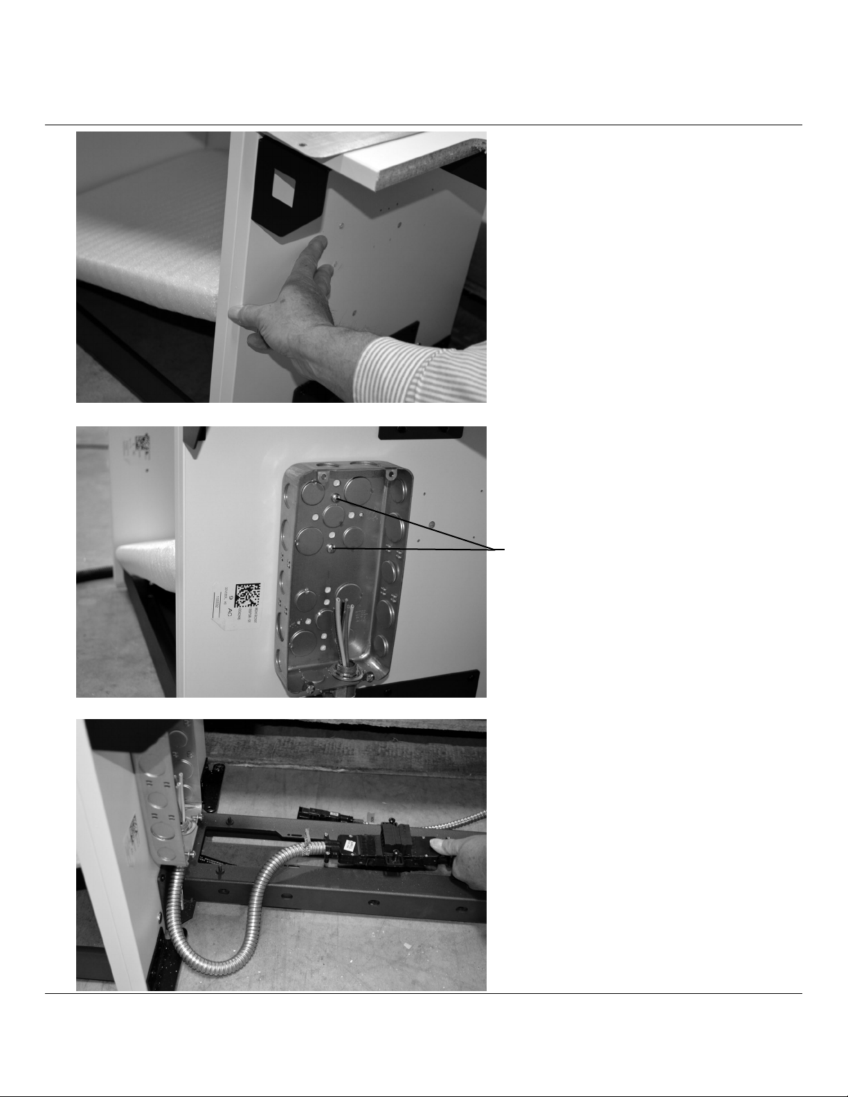
7. Remove bottom shelf to
gain access to harness.
A
D
E

Z
© 2015 Herman Miller, Inc. Zeeland, Michigan. Printed in the U.S.A.
TM Locale is among the trademarks of Herman Miller, Inc.
Illustrations and specifications are based on the latest product information available at the time of publication.
The right is reserved to make changes in design and specifications at any time, without notice, and also to discontinue products.
Part no. 1bc57y rev B.
4
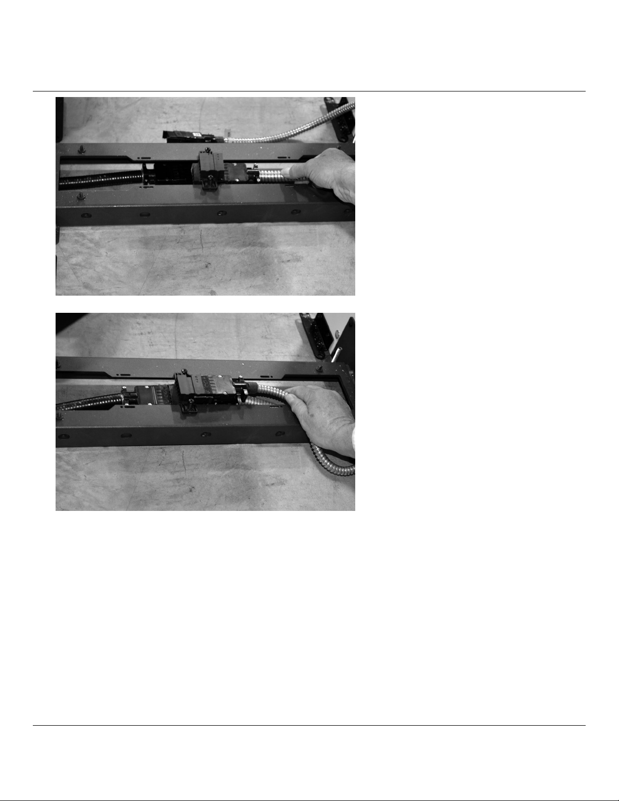
8. Run end of Power Block (B)
through inner wall of Base.
9. Insert end of harness into
Power Block. Make sure
connection fully engages.
10. When making connections
to Power Block, Make
sure reference arrow point
in same direction.
1. Remove Lid from Modular Power Entry (F).
Modular Power Entry For New York City:
F
Arrow
Arrow
Z
© 2015 Herman Miller, Inc. Zeeland, Michigan. Printed in the U.S.A.
TM Locale is among the trademarks of Herman Miller, Inc.
Illustrations and specifications are based on the latest product information available at the time of publication.
The right is reserved to make changes in design and specifications at any time, without notice, and also to discontinue products.
Part no. 1bc57y rev B.
5
2. Locate mounting holes
for mounting Modular Power
Entry (F).
3. Secure Modular Power
Entry (F) to inside wall of
Base with 2 screws supplied
with product.
4. Insert end of Power Block into
Block. Make sure connection
fully engages.
Supplied with Product

Z
© 2015 Herman Miller, Inc. Zeeland, Michigan. Printed in the U.S.A.
TM Locale is among the trademarks of Herman Miller, Inc.
Illustrations and specifications are based on the latest product information available at the time of publication.
The right is reserved to make changes in design and specifications at any time, without notice, and also to discontinue products.
Part no. 1bc57y rev B.
6
5. After hard wiring J-Box
from an outside power
source by a qualied
electrician, return cover to
J-Box.
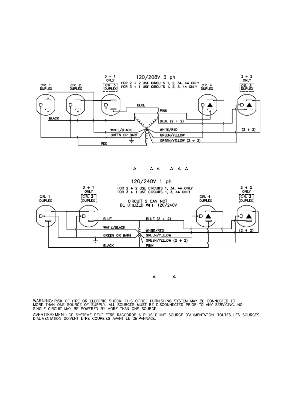
1. Insert Block-to-Block
Jumper (G) through opening
in side of Base.
2. Remove Bottom Shelf.
Feed Jumper through inner
wall of base.
Block-to-Block Jumper:
G
Z
© 2015 Herman Miller, Inc. Zeeland, Michigan. Printed in the U.S.A.
TM Locale is among the trademarks of Herman Miller, Inc.
Illustrations and specifications are based on the latest product information available at the time of publication.
The right is reserved to make changes in design and specifications at any time, without notice, and also to discontinue products.
Part no. 1bc57y rev B.
7
4. Connect Modular Power
Duplex to Power Block.
3. Insert end of Jumper into
Bottom Port of Power
Block. Make sure
connection fully engages.
Z
© 2015 Herman Miller, Inc. Zeeland, Michigan. Printed in the U.S.A.
TM Locale is among the trademarks of Herman Miller, Inc.
Illustrations and specifications are based on the latest product information available at the time of publication.
The right is reserved to make changes in design and specifications at any time, without notice, and also to discontinue products.
Part no. 1bc57y rev B.
8
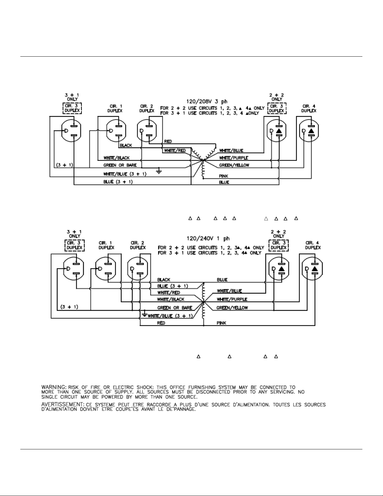
8 WIRE POWER BLOCK WIRING DIAGRAMS 4-2-2
4 HOTS, 2 NEUTRALS, 2 GROUNDS
NOTE: CIRCUITS 1,2,3,4 CORRESPOND TO CIRCUITS (DUPLEX RECEPTACLES) A, B, C, D
ALLOWABLE CIRCUIT COMBINATIONS: 1,2,3,4 ; 1,2,3 ,4 ; 1, 2 ,3 ,4
NOTE: CIRCUITS 1, 3, 4 CORRESPOND TO CIRCUITS (DUPLEX RECEPTACLES) A, C, D
ALLOWABLE CIRCUIT COMBINATIONS: CIRCUITS 1, 3, 4 ; 1, 4, 3 ; OR 1, 3, 4
Z
© 2015 Herman Miller, Inc. Zeeland, Michigan. Printed in the U.S.A.
TM Locale is among the trademarks of Herman Miller, Inc.
Illustrations and specifications are based on the latest product information available at the time of publication.
The right is reserved to make changes in design and specifications at any time, without notice, and also to discontinue products.
Part no. 1bc57y rev B.
9
10 WIRE POWER BLOCK WIRING DIAGRAMS 4-4-2
4 HOTS, 4 NEUTRALS, 2 GROUNDS
ALLOWABLE CIRCUIT COMBINATIONS: 1,2,3,4 ; 1,2,3 ,4 ; 1, 2 ,3 ,4 ; 1,2,3,4,1 ,2 ,3 ,4
ALLOWABLE CIRCUIT COMBINATIONS: CIRCUITS 1,2, 3, 4 ; 1, 2, 3,4 ; OR 1, 2, 3 ,4

Z
© 2015 Herman Miller, Inc. Zeeland, Michigan. Printed in the U.S.A.
TM Locale is among the trademarks of Herman Miller, Inc.
Illustrations and specifications are based on the latest product information available at the time of publication.
The right is reserved to make changes in design and specifications at any time, without notice, and also to discontinue products.
Part no. 1bc57y rev B.
10
Disassembly and Recycling:
Materials Identication and Segregation:
Where possible, plastic components are marked with ASTM recycling codes. Use
these codes to identify material type for recycling. Non-marked components should
be treated as mixed plastic. Ferrous metals can be identied using a small magnet
for recycling. Non-ferrous metals should be separated and recycled separately.
To disassemble product, reverse the above installation steps.
Popular Industrial Electrical manuals by other brands

Murata
Murata GRM0335C1H5R9CA01 Series Reference sheet

Murata
Murata GRM1555C2A7R9DA01 Series Reference sheet

Murata
Murata GRM033R71H471MA12 Series Reference sheet

Pepperl+Fuchs
Pepperl+Fuchs H-System manual

centor
centor ARES Basic III Guard Tour Verification... manual

Condux
Condux Gulfstream 350e User's guide & safety manual


Murata
Murata GRM0335C1E150JA01 Series Reference sheet

Siemens
Siemens TSCLTM operating instructions

Murata
Murata GRM155D70J225ME44 Series Reference sheet

Murata
Murata GCM2165C1H151JA16 Series Reference sheet

Murata
Murata GRM1555C1H8R0DA01 Series Reference sheet

Murata
Murata GQM22M5C2H7R0BB01 Series Reference sheet