Mitsubishi MOTORS DY-5MU4R69-T User manual

SERVICE MANUAL
MITSUBISHI ELECTRIC CORP. SANDA WORKS
Your company internal use only.
DY-5MU4R69-T,-2
Copyright (C) Mitsubishi Electric Corporation.
SE045613053E Ver.ppt11E
MITSUBISHI MOTORS 2013 Aug.
AM / FM-ST ELECTRONIC TUNING RADIO,
CD PLAYER
CONTENTS
Model : DY-5MU4R69-T,-2
MELCO Code : 34U277,34W894
PART No. : 8071A408,8701A408
● FEATURES .........................................................................2
● SPECIFICATIONS ..............................................................3
● OPERATION .......................................................................4
● CONNECTORS ...............................................................5,6
● SYSTEM CONFIGURATION ..............................................7
● BLOCK DIAGRAM ..............................................................8
● DISASSEMBLING PROCEDURES ............................. 9~25
● PARTS LIST.................................................................26,27
● ELECTRICAL PARTS LIST........................................ 28~43
● PARTS LAYOUT ON PRINTED CIRCUIT BOARD .... 44~55
● SCHEMATIC DIAGRAM
PCB-MAIN .....................................................................56
PCB-MEDIA..............................................................57,58
PCB-MONI.....................................................................59
PCB-DCDC....................................................................60
PCB-SW-L .....................................................................61
PCB-SW-R.....................................................................62
● VOLTAGE .................................................................. 63~70
● WAVEFORM .....................................................................71

2Your company internal use only.Copyright (C) Mitsubishi Electric Corporation.
DY-5MU4R69-T,-2
FEATURES
< Audio part >
●MAIN CPU : V850ES/SJ3
●MEDIA CPU : SH7262 (SH2A/Internal operating frequency 144 MHz)
●CAN-BUS CPU : M16C5L
●Memory
[ For MAIN CPU ]
- EEPROM(64KB)
- CMOS SERIAL FLASH(8MB)
[ For MEDIA CPU ]
- SDR-SDRAM (16MB)
- NOR-FLASH (8MB)
●AM/FM tuner : CDSP : DiRaNa2 + DigitalTunerIC : LeafDice×2
●CD mechanism : CD8 mechanism (955829)
●USB / iPod *
[ USB ]
- Playback of compressed music files, MP3/WMA/AAC
[ iPod ]
- Controllable from the unit
- Video playback
< Monitor part >
●LCD
- 6.1 inch WQVGA
●Touch panel
- Analog transparent touch panel
(without retardation film, AGcoating)
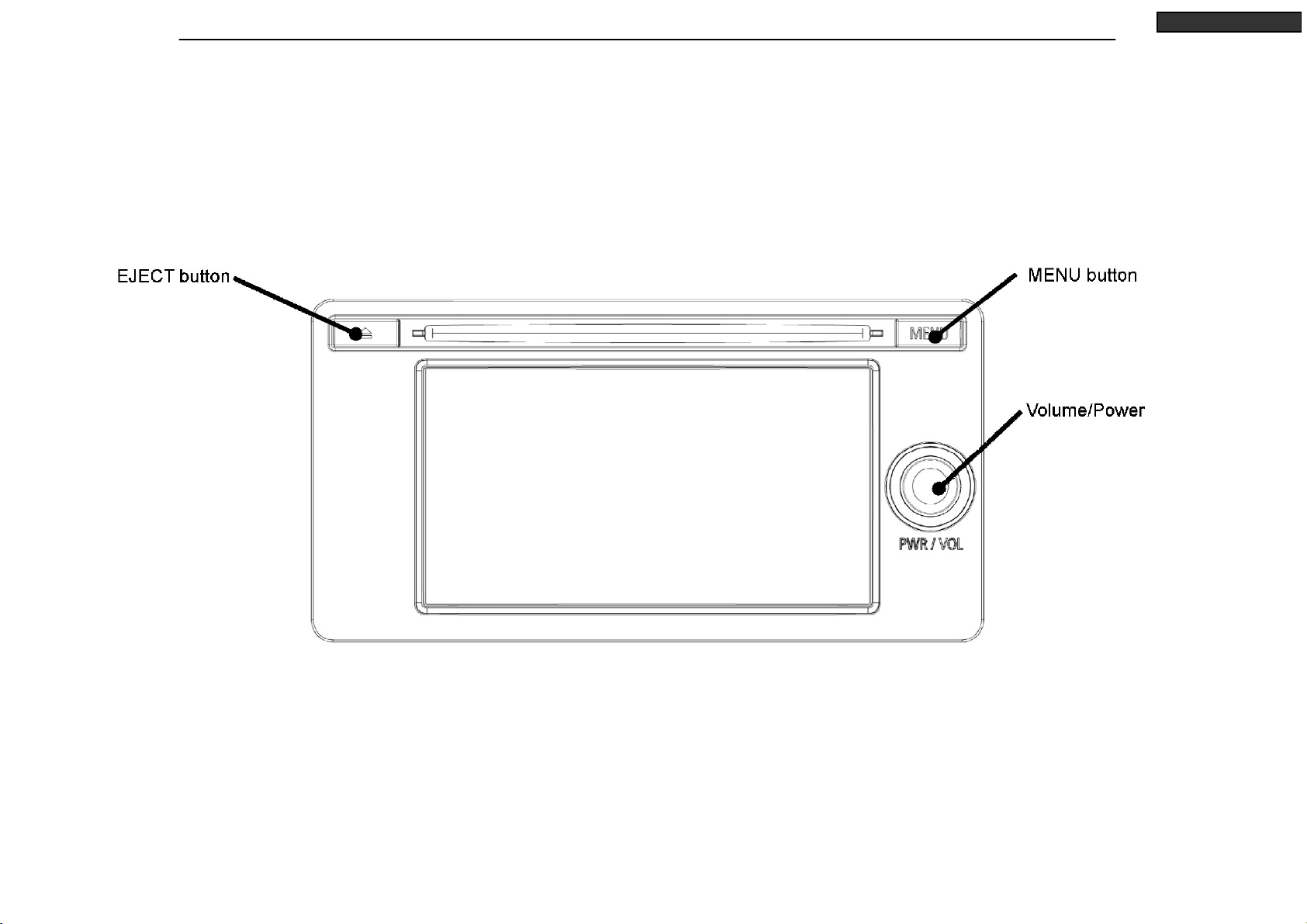
●Operation key
- Power/Volume : Rotary encoder
- MENU, EJECT : Tact switch
< External device input/output >
●Connectable device
- Satellite tuner
- HFM(JCI)
-AfterHFM
- Premium AMP
- Rear camera
- RSES (sound input from AUX terminal only)
< Others >
●Main function
- MS-CAN supported
- IE-BUS supported
- Handle remote control supported
* The built-in iPod/USB function and the iPod/USB function using
JCI-HFM should also be connected exclusively.

3Your company internal use only.Copyright (C) Mitsubishi Electric Corporation.
DY-5MU4R69-T,-2
SPECIFICATIONS
●Voltage rating : 13.2V
●Operating voltage : 10.0V ~ 16.0V (battery and accessory line)
●Grounding polarity : Minus
●Backup Current : Max. 2.0mA (*1)
●Consumption current : Max. 10A Typ.3A (*2)
●Output : 45W ×4ch Max power (at 14.4V)
●Storage temperature range : -30℃~ +85℃
●Guaranteed operating temperature range : -20℃~ +65℃(*3)
●Operating temperature (Reference information) of Back FAN.
FAN OFF →ON : More than +50℃.
FAN ON →OFF : Less than +40℃.
●Dimensions : 206(W)×105.4(H)×190(D) mm
●Weight : 2.3kg
(*1) Measured at ambient temperature, without connecting options,
without inserting a CD, at power supply voltage of 13.2V,
90 seconds after ACC is turned OFF.
(*2) Typ value at ambient temperature without connecting options,
during CD playback (1kHz, 0dB, 1W output), at the maximum monitor
brightness, and at power supply voltage of 13.2V.
(*3) The high temperature detection setting for the CD mechanism is not used.
< AM Radio >
●Frequency Range
NAS : 530 ~ 1710kHz (10kHz step)
●Usable Sensitivity : Less than 34dB
●Signal/Noise Ratio (60dBμV) : More than 45dB
< FM Stereo Radio >
●Frequency Range
NAS : 87.75 ~ 107.9MHz (0.2MHz step)
●Limiting Sensitivity : Less than 10dB
●Signal/Noise Ratio (40dBμV) : More than 55dB
< CD Player >
●Dynamic Range : More than 65dB
●Signal/Noise Ratio : More than 65dB
●Channel Separation (1kHz) : More than 55dB
4Your company internal use only.Copyright (C) Mitsubishi Electric Corporation.
DY-5MU4R69-T,-2
OPERATION
5Your company internal use only.Copyright (C) Mitsubishi Electric Corporation.
DY-5MU4R69-T,-2
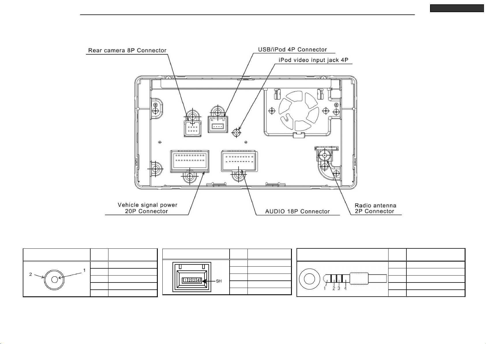
CONNECTORS
(Note)
Figure of connector seen from rear of unit.
USB/iPod 4P Connector PinNo. Signal Name
1Vbus
2D-
3D+
4GND
SH USB SH
Radio antenna 2P
Connector PinNo. Signal Name
1SIG
2 RADIO ANT GN D
iPod video input jack 4P PinNo. Signal Name
1 CVBS_iPod
2 -
3V_GND
4 iPod_VIDEO_DETECT

6Your company internal use only.Copyright (C) Mitsubishi Electric Corporation.
DY-5MU4R69-T,-2
CONNECTORS
(Note)
Figure of connector seen from rear of unit.
PinNo. Signal Name PinNo. Signal Name
1 IE-BUS+ 10 IE-BUS-
2 IE_SYSTEM-ACC 11 GND
3 IE_L+ 12 IE_L-
4 IE_R+ 13 IE_R-
5 TEL_IN 14 TEL_MUTE
6 HFM_L 15 TEL_GND
7 HFM_R 16 HFM_GND
8 AUX_L 17 GND
9 AUX_R 18 AUX_GND
AUDIO 18P Connector
PinNo. Signal Name PinNo. Signal Name
1+B 11GND
2 ILL+ 12 ILL-
3 FL+ 13 FL-
4 RL+ 14 RL-
5FR+ 15FR-
6 RR+ 16 RR-
7 SHIELD-GND 17 P-ANT
8 CAN+ 1 8 C AN -
9 STEERING REMOCON 19 REMO-GND
10 ACC 20 SPEED
Vehicle signal power 20P Connector
PinNo. Signal Name PinNo. Signal Name
1 - 5 -
2 PS-R 6 SHIELD(CAMERA)
3 CAMER A_ D ETECT 7 CAMER A_ SIGN AL
4 VCC(RC6.5V) 8 GND(RC)
Rear camera 8P Connector
7Your company internal use only.Copyright (C) Mitsubishi Electric Corporation.
DY-5MU4R69-T,-2
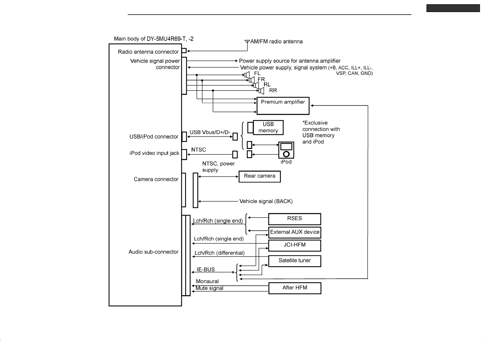
SYSTEM CONFIGURATION
8Your company internal use only.Copyright (C) Mitsubishi Electric Corporation.
DY-5MU4R69-T,-2
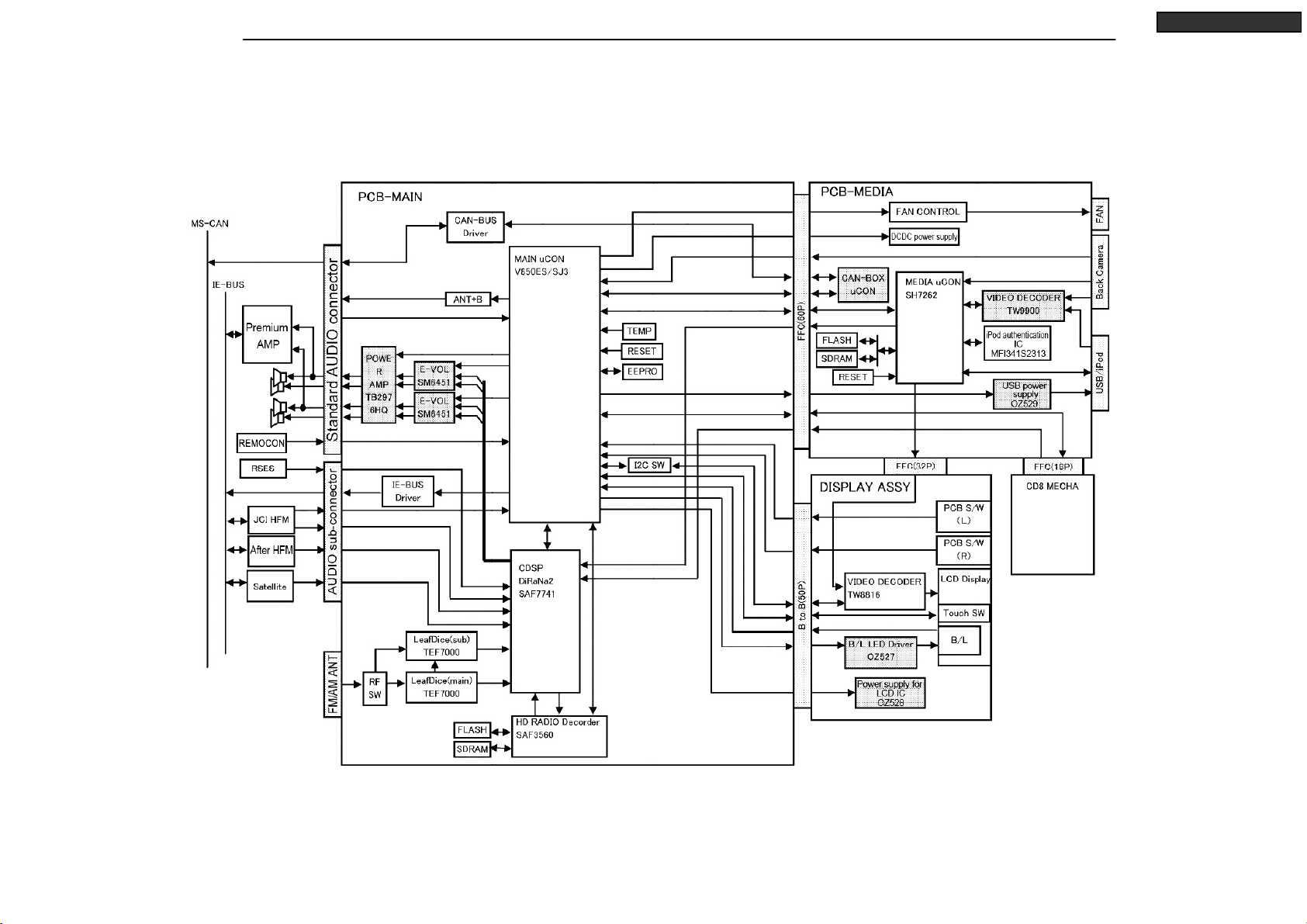
BLOCK DIAGRAM

9Your company internal use only.Copyright (C) Mitsubishi Electric Corporation.
DY-5MU4R69-T,-2
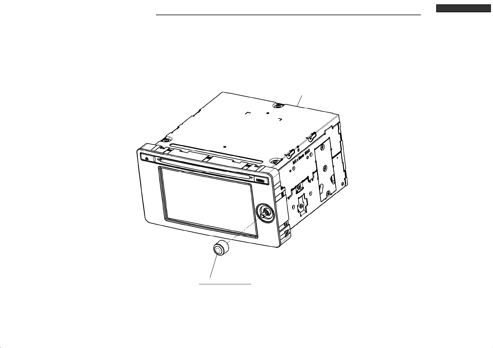
DISASSEMBLING PROCEDURES
M027(1) : NAME-CARD(DY-5MU4R69-T)
M028(2) : NAME-CARD(DY-5MU4R69-T-2)
*It is assembling procedure. Disassembling procedure is in reverse.
M019(1) / M020(2) : LABEL
(1) DY-5MU4R69-T
(2) DY-5MU4R69-T-2
Model
10 Your company internal use only.Copyright (C) Mitsubishi Electric Corporation.
DY-5MU4R69-T,-2
DISASSEMBLING PROCEDURES
M025 : ASSY-KNOB
S2-CHASSIS
●Disassembling procedures
In reverse of assembling procedures.
●Assembling procedures
1. Attach M025 to S2-CHASSIS.
11 Your company internal use only.Copyright (C) Mitsubishi Electric Corporation.
DY-5MU4R69-T,-2
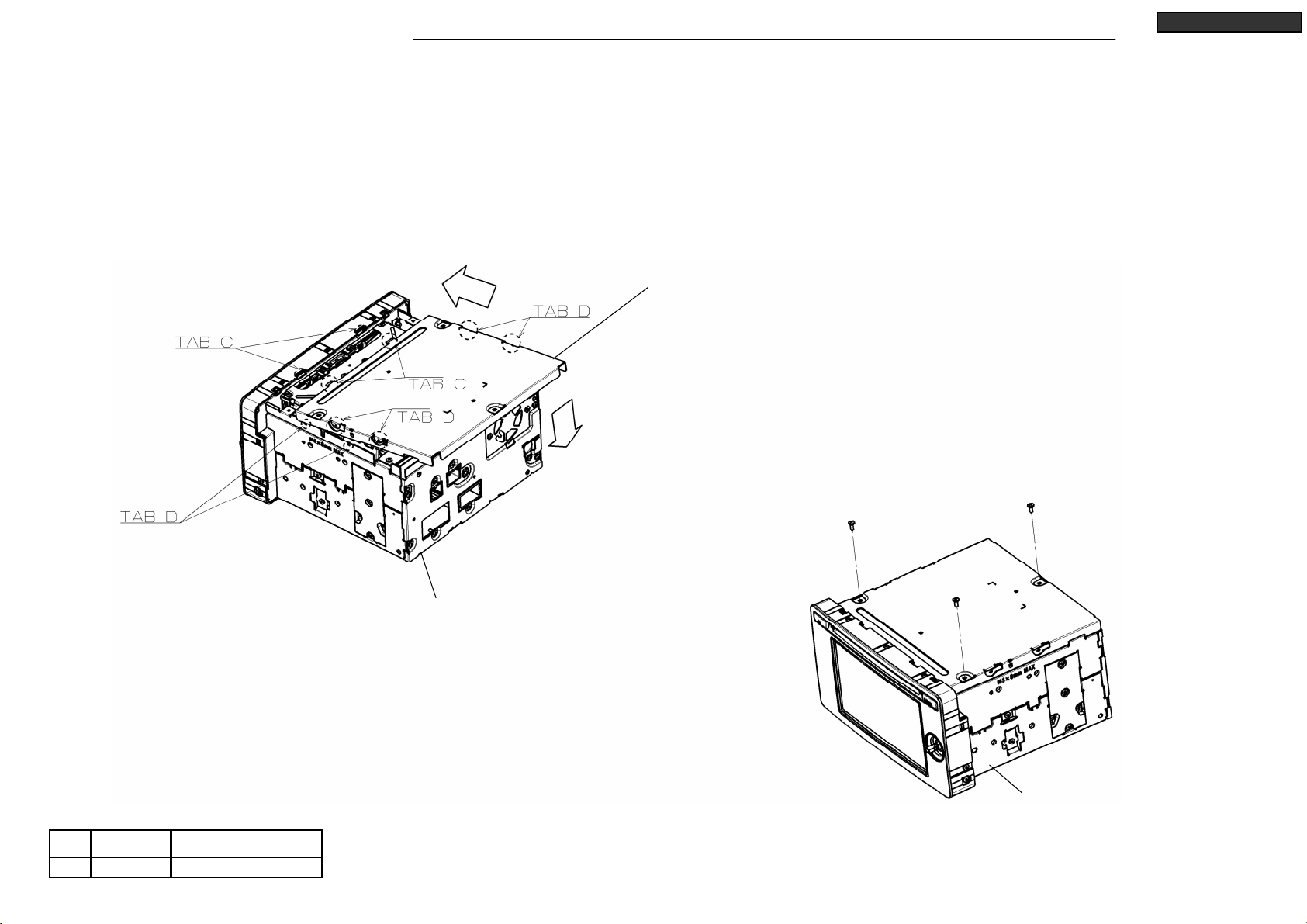
DISASSEMBLING PROCEDURES
Ⓔx 3
●Disassembling procedures
In reverse of assembling procedures.
●Assembling procedures
1. Fit tab C of M012 on tab C of S2-CHASSIS (2 places) to direction arrow.
And fit tab D of M012. (4 places)
2. Screw S2-CHASSIS and M012 with Ⓔ. (3 places)
S2-CHASSIS
S2-CHASSIS
Ⓔ
No.
0.5 +0.2/-0.12.6X6
Tighten torque(N・m)Screw
M012 : COVER
12 Your company internal use only.Copyright (C) Mitsubishi Electric Corporation.
DY-5MU4R69-T,-2
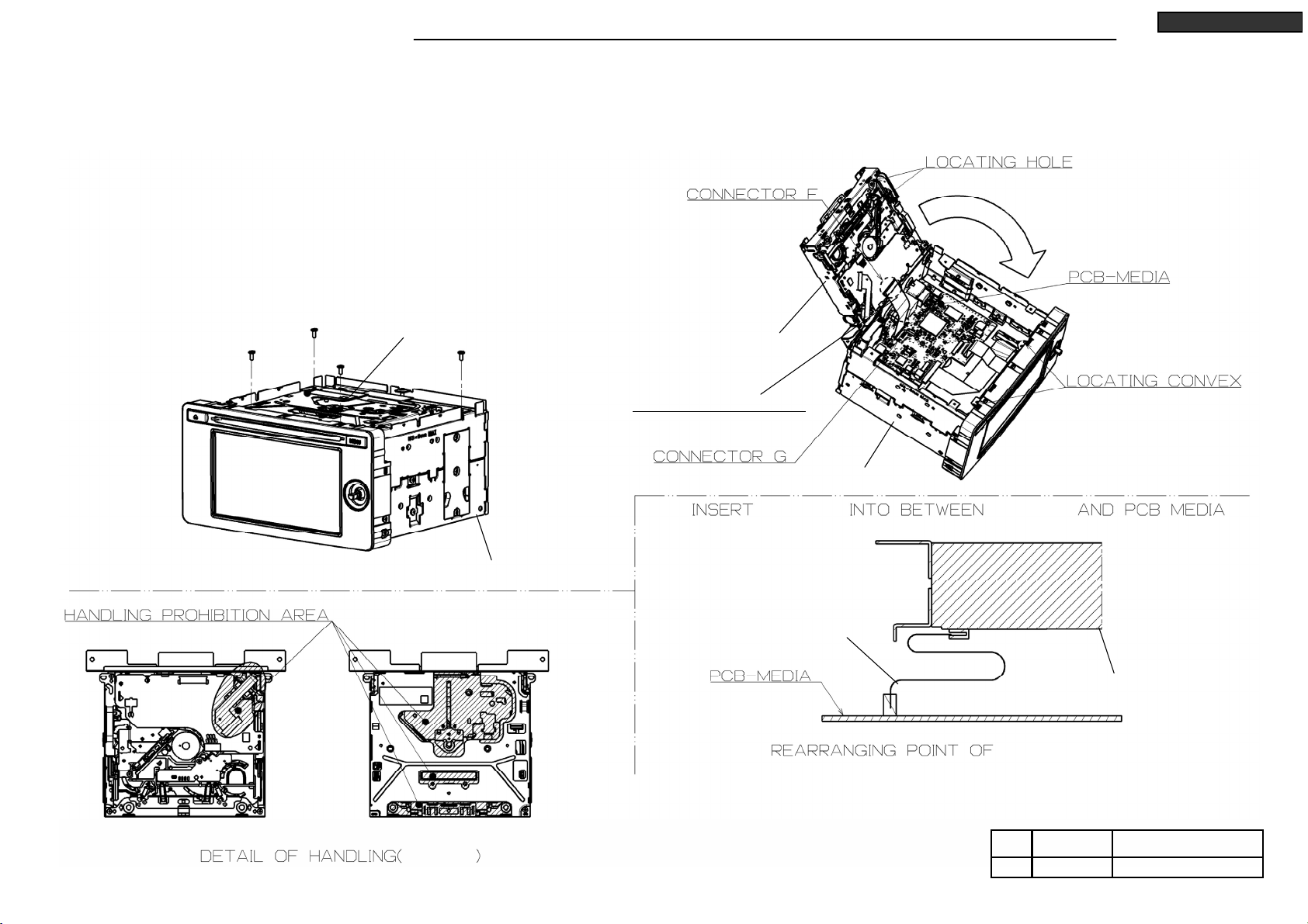
DISASSEMBLING PROCEDURES
Ⓔx 4
●Disassembling procedures
In reverse of assembling procedures.
●Assembling procedures
1. Insert M003 to S2-DECK and PCB-MEDIA.
*Lock connector after inserting M003.
2. Positioning S2-DECK to S2-CHASSIS and fit S2-DECK to S2-CHASSIS.
*Handling range of S2-DECK is follow the indicates in view on left.
*Rearranging method is follow the indicates in view on right.
3. Screw S2-CHASSIS and S2-DECK with Ⓔ. (4 places)
Ⓔ
No.
0.5 +0.2/-0.12.6X6
Tighten torque(N・m)Screw
S2-DECK
S2-CHASSIS
S2-CHASSIS
M003 : FLAT-CABLE 18P
S2-DECK
S2-DECK
M003 S2-DECK
M003
S2-DECK
M003
13 Your company internal use only.Copyright (C) Mitsubishi Electric Corporation.
DY-5MU4R69-T,-2
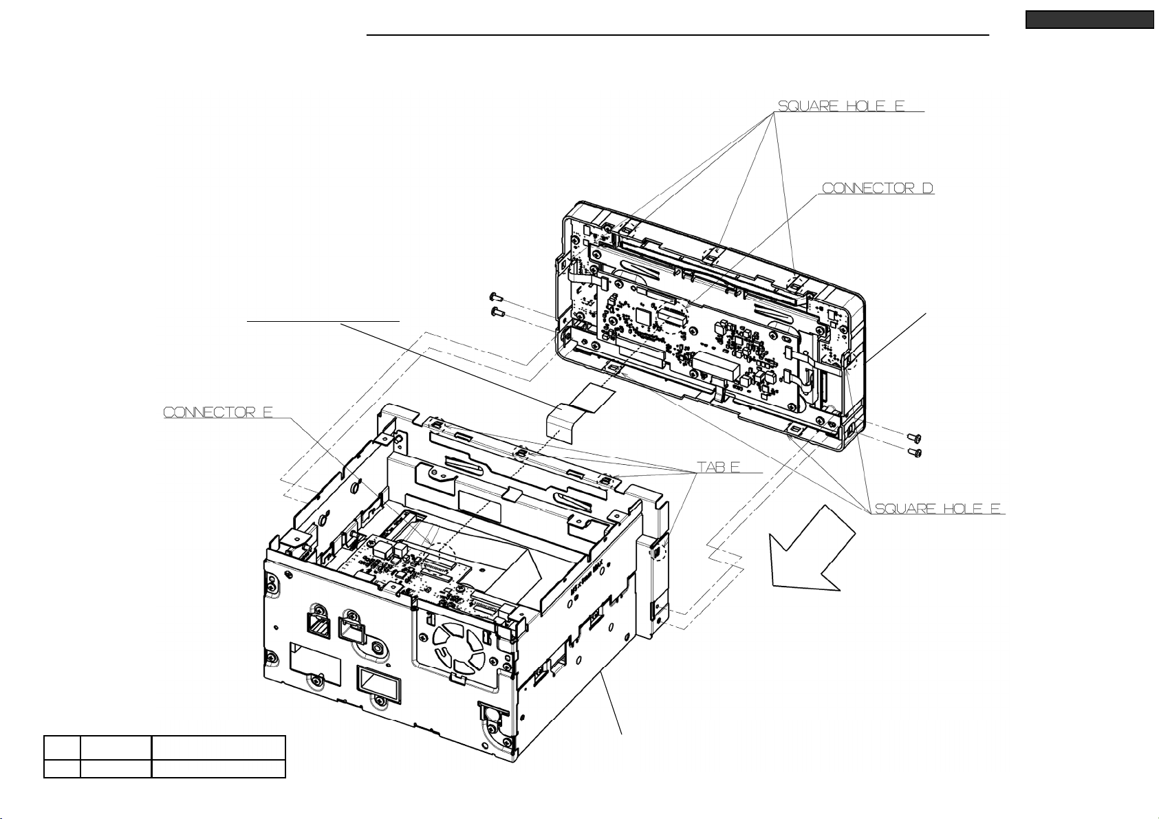
DISASSEMBLING PROCEDURES
S2-CHASSIS
Ⓐx 2
Ⓐ
No.
0.5 +0.2/-0.12.6X6
Tighten torque(N・m)Screw
Ⓐx 2
●Disassembling procedures
In reverse of assembling procedures.
●Assembling procedures
1. Insert M002 to the connector of S2-PANEL. (Connector D)
*Lock connector after inserting M002.
2. Fit tab E of S2-CHASSIS on square hole E of S2-PANEL (7 places),
Screw S2-CHASSIS and S2-PANEL with Ⓐ. (4 places)
3. Insert M002 to the connector of S2-CHASSIS. (Connector E)
*Lock connector after inserting M002.
S2-PANEL
M002 : FLAT-CABLE 30P

14 Your company internal use only.Copyright (C) Mitsubishi Electric Corporation.
DY-5MU4R69-T,-2
DISASSEMBLING PROCEDURES
M004 : FLAT-CABLE 60P
●Disassembling procedures
In reverse of assembling procedures.
●Assembling procedures
1. Insert M004 to the connector A and B.
*Lock connector after inserting M004.
S2-CHASSIS S2-CHASSIS
15 Your company internal use only.Copyright (C) Mitsubishi Electric Corporation.
DY-5MU4R69-T,-2
DISASSEMBLING PROCEDURES
●Disassembling procedures
In reverse of assembling procedures.
●Assembling procedures
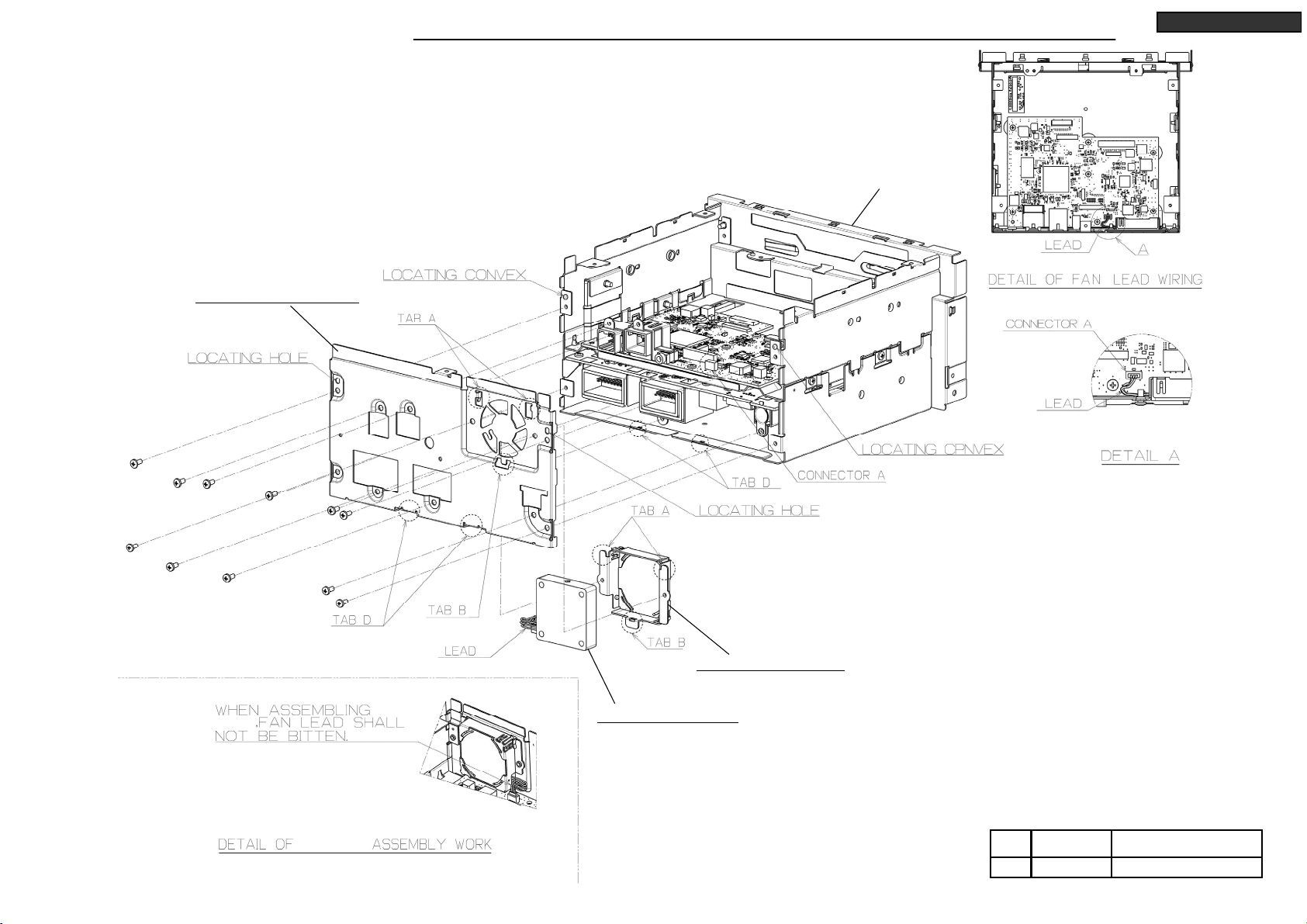
1. After put M005 to M014, tab A and B of M014 fit on tab A and B of M009 and screw with Ⓔ. (2 places)
2. Insert lead to connector A.
3. Fitting tab D after inserting the convex position of S3-CHASSIS
into the locating hole of M009.
4. Screw M009 and S3-CHASSIS with Ⓔ. (9 places)
Ⓔx 11
Ⓔ
No.
0.5 +0.2/-0.12.6X6
Tighten torque(N・m)Screw
M014,M005
M009 M005 : MOTOR-FAN
M014 : HOLDER-FAN
M009 : CHASSIS-REAR
S3-CHASSIS

16 Your company internal use only.Copyright (C) Mitsubishi Electric Corporation.
DY-5MU4R69-T,-2
DISASSEMBLING PROCEDURES
S3-CHASSIS
●Disassembling procedures
In reverse of assembling procedures.
●Assembling procedures
1. After inserting the convex position of S3-CHASSIS into the locating hole of M008,
screw M008 and S3-CHASSIS with Ⓔ. (4 places)
Ⓔx 4
Ⓔ
No.
0.5 +0.2/-0.12.6X6
Tighten torque(N・m)Screw
M008 : CHASSIS-F
17 Your company internal use only.Copyright (C) Mitsubishi Electric Corporation.
DY-5MU4R69-T,-2
DISASSEMBLING PROCEDURES
●Disassembling procedures
In reverse of assembling procedures.
●Assembling procedures
1. Insert the locating convex of S4-CHASSIS into the locating groove of CHASSIS-M. (2 places)
2. Screw CHASSIS-M and S4-CHASSIS with Ⓔ. (3 places)
3. Screw M016 and S4-CHASSIS with Ⓔ(3 places) and Ⓕ. (2 places)
4. Screw S4-CHASSIS and CHASSIS-M with Ⓕ. (1 places)
CHASSIS-M
S4-CHASSIS
Ⓔx 4
ⒻⒻ
Ⓔx 2
M016 : HEAT-SINK
0.5 +0.2/-0.12.6X6Ⓔ
Ⓕ
No.
0.5 +0.2/-0.12.6X12
Tighten torque(N・m)Screw
Ⓕ

18 Your company internal use only.Copyright (C) Mitsubishi Electric Corporation.
DY-5MU4R69-T,-2
DISASSEMBLING PROCEDURES
Ⓔx 7
M007 : CHASSIS-M
M029 : ASSY-PCB-MEDIA
Ⓔ
No.
0.5 +0.2/-0.12.6X6
Tighten torque(N・m)Screw
●Disassembling procedures
In reverse of assembling procedures.
●Assembling procedures
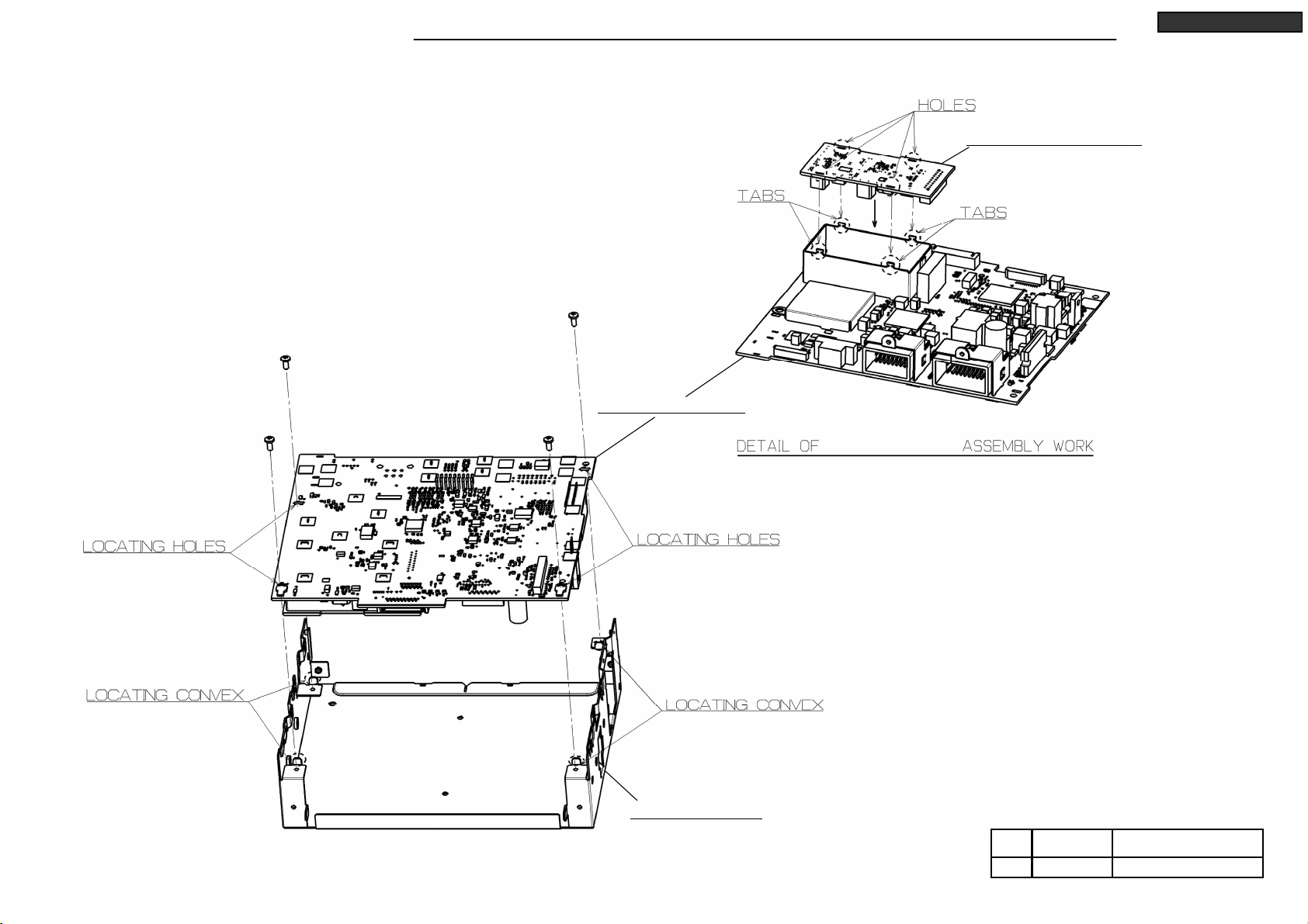
1. Insert the locating convex of M007 into the locating hole of M029. (2 places)
And fit M007 to M029.
2. Screw M029 with Ⓔ. (7 places)
19 Your company internal use only.Copyright (C) Mitsubishi Electric Corporation.
DY-5MU4R69-T,-2
DISASSEMBLING PROCEDURES
Ⓔx 4
Ⓔ
No.
0.4 ±0.12.6X6
Tighten torque(N・m)Screw
●Disassembling procedures
In reverse of assembling procedures.
●Assembling procedures
1. Insert 4 tabs of M021 to 4 holes of M031, and twist 4 tabs.
2. After inserting locating hole on M021 into locating convex on M006,
screw with Ⓔ. (4places)
M021 : S5-PCB-MAIN
M006 : CHASSIS-B
M031 : ASSY-PCB-DCDC
M021

20 Your company internal use only.Copyright (C) Mitsubishi Electric Corporation.
DY-5MU4R69-T,-2
DISASSEMBLING PROCEDURES
●Disassembling procedures
In reverse of assembling procedures.
●Assembling procedures
1. After inserting the locating convex of M013 into the locating hole of M026,
screw M026 and M013 with Ⓓ. (2 places)
2. Note that M026 handling prohibited area.
Ⓓ
No.
0.8 +0.2/-0.13X6
Tighten torque(N・m)Screw
Ⓓx 2
M026
M013 : HOLDER-CD8
M026 : CD8-MECHA(955829)
This manual suits for next models
1
Table of contents
Other Mitsubishi MOTORS Radio manuals


