CONTENTS
Pages
FEATURES
AND
FUNCTIONS
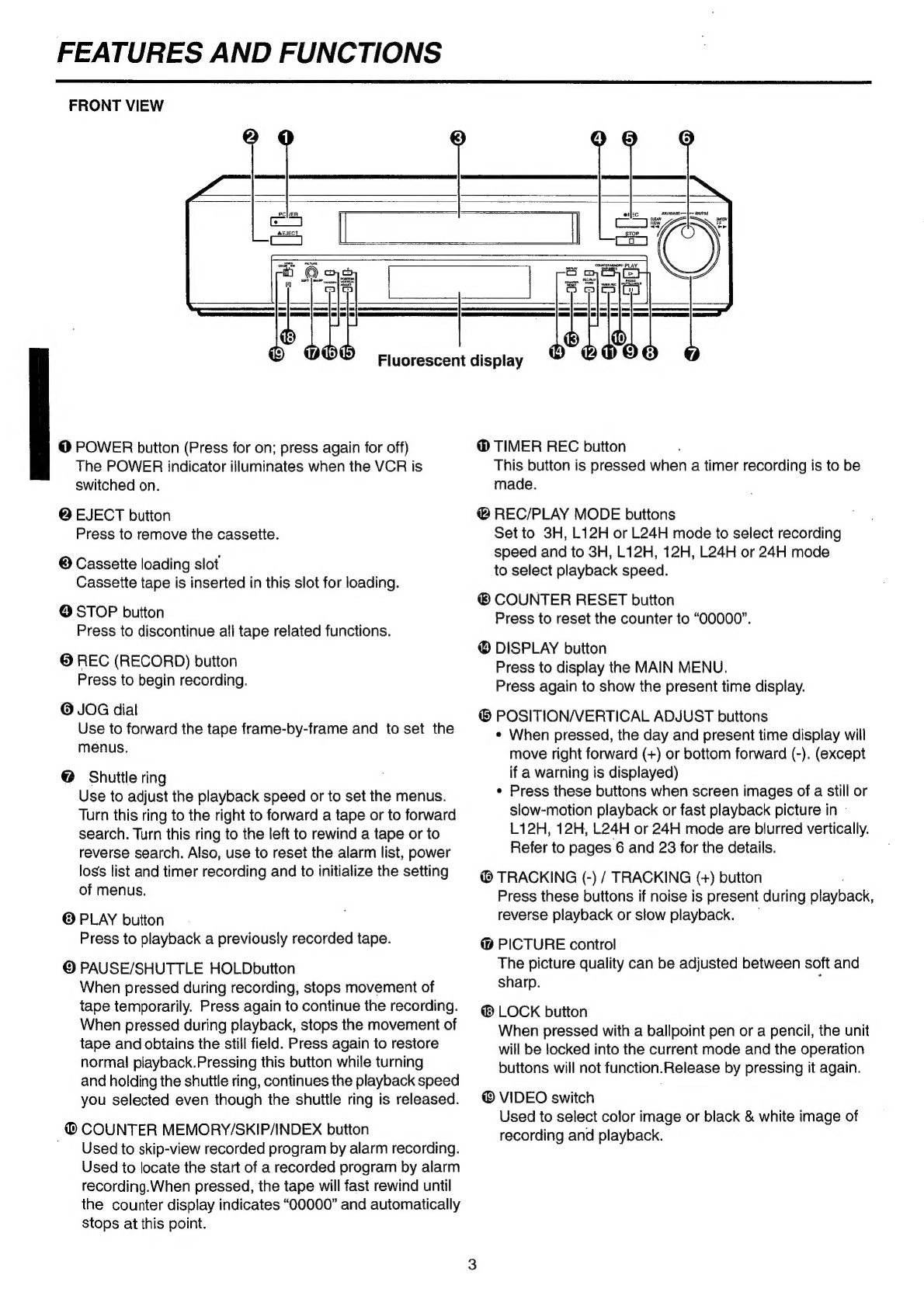
FRONEVIOW
vec.
eeceedebincdescvstascedtaelvduzelewensecs
emegueenctneenedtevas
les
3
Fluorescent
display
........ccscccccesseccesessesssessseneesesseseessareenessaee
4
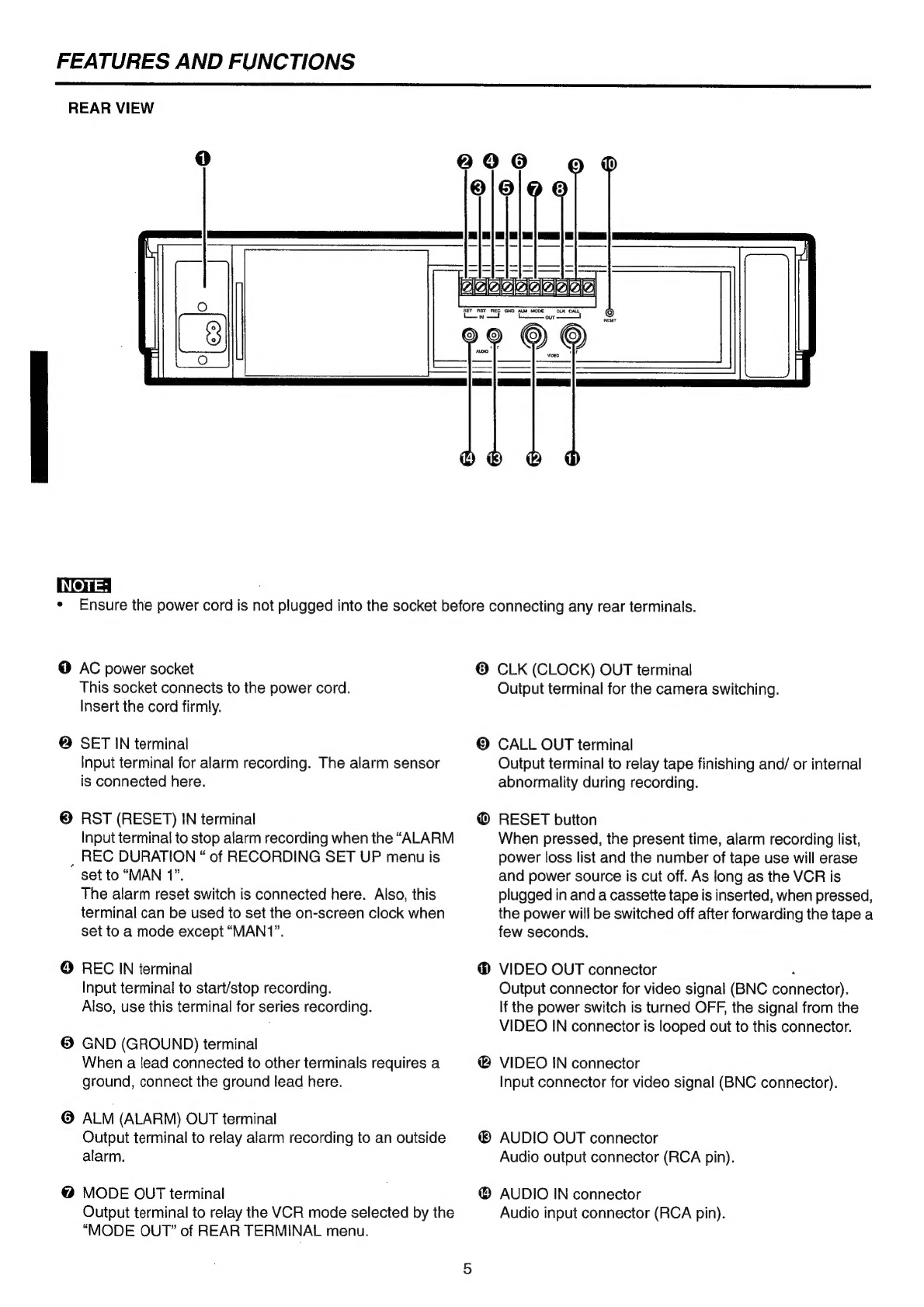
Rar
ViGW
ics.
iva
ete
seessioAtdate
cnssievities
ta
RAs
ethers
hiveceents
5~
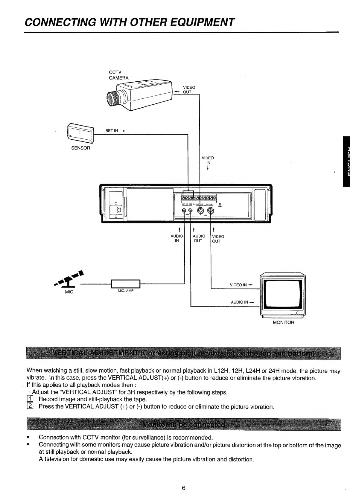
CONNECTING
WITH
OTHER
EQUIPMENT
.........:cscsssseseseessees
6
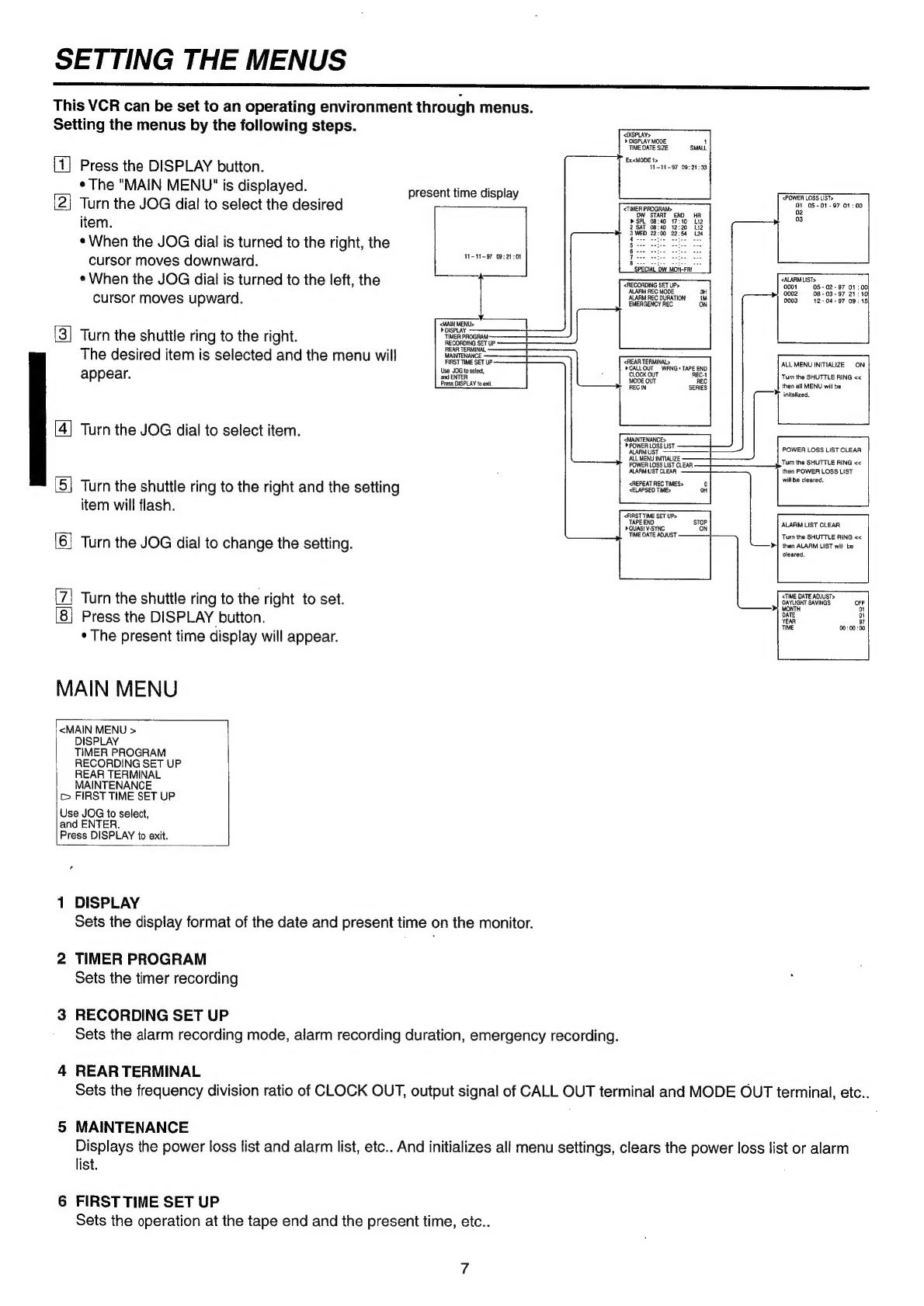
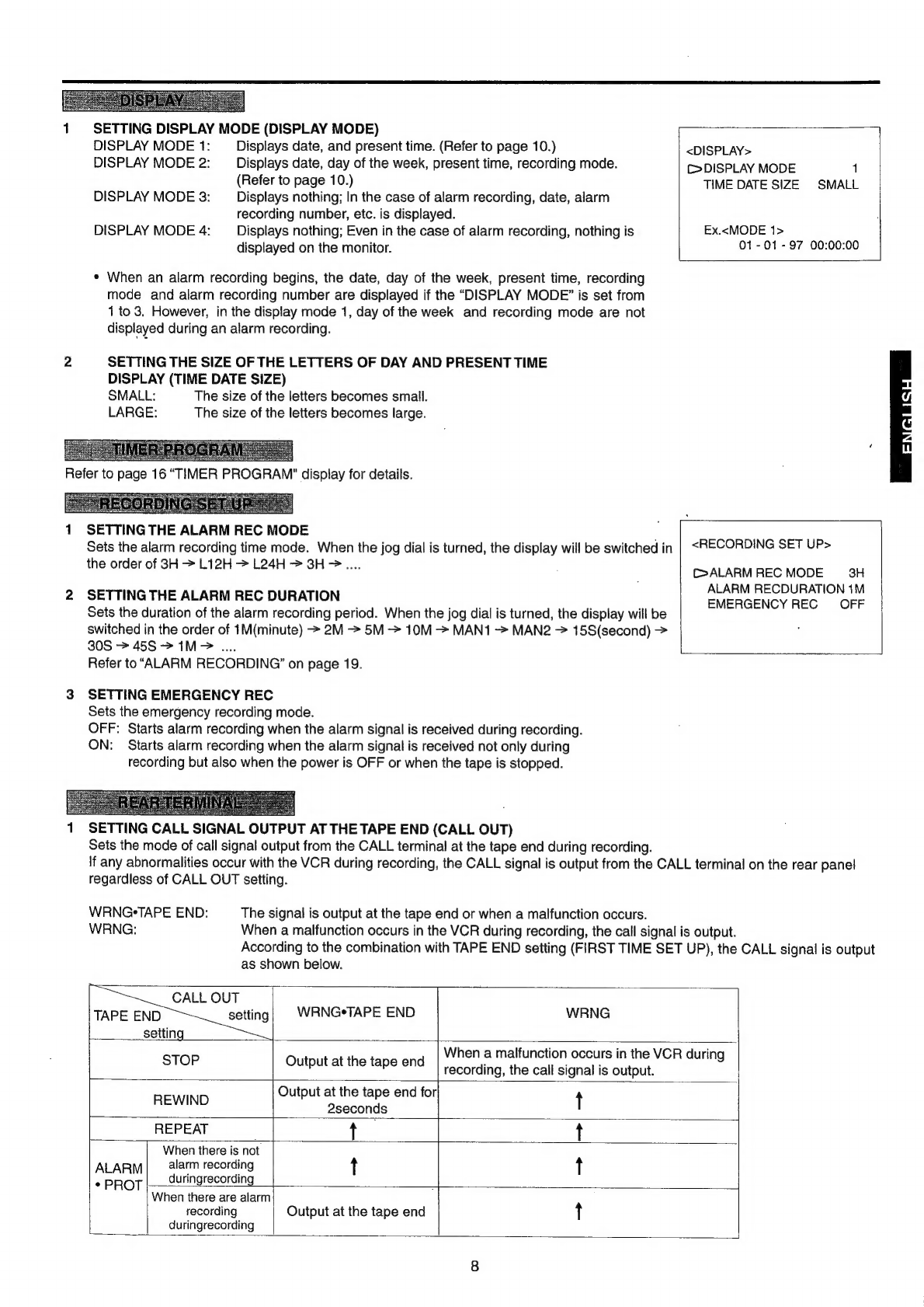
SETTING
THE
MENUS
..........ccsccsseesscsssesesesneuenensneeenesaneeee
7,
8,9
SETTING
THE
PRESENT
TIME
..........csssecsescecseesssesesesesees
10,11
LOADING
AND
UNLOADING
THE
CASSETTE
TAPE
...........
12
MANUAL
RECORDING
...0....
cee
eecceceseteeteteeteeteeeseenens
13,
14
AUDIO
TOCOMCING
ciinscsscevasccsecteeeeccssssadesenectvasteves
cosuteatiosvectintess
13
Repeat
recording
........csscsscssssessecssscsssestsessereesseeseessscesesseees
14
SEri@S
rECOPING
........csccessecsscssscsescssessssesscesseneessecsseseseeseness
14
ADDITIONAL
FEATURES
COUNter
MEMOTY
0.0...
eceectcesceseteesceseeseeeeeeeaseeceateasneeteneesaeee®
15
TAPS:
COUMCT
i
5255,5escscei
cases
ishaseticcasseecacdlndotan
a
sescsttecderieaccdy
15
Counter
POSEt
iii
dcteccuseidi
es
satecneiuthacss
ce
rOecettesiceuteinttenlievives
15
Memory
back-up
in
case
of
power
failure
........
cesses
15
Recording
after
a
power
failure
........
ec
cceesesserteetseeseeseeeee
15
Power
failure
time
display
.............::ccssccessseeesssreecesteeeseeeeeees
15
Elapsed
time
display
..........:ccesccseceecssessseessseeesseeeereeeaeeeeeees
15
FEATURES
Up
to
27
hours
of
recording:
|
Pages
TIMER
RECORDING
o.oo.
ecenenteteseteeceeeeeteaeennees
16,17
ALARM
RECORDING
...........:ccssscsreesnssseesercserseressteenees
18,
19,
20
Alarm
recording
CONNECTION
........
ce
eeteesteseeeestrerseeseeeesneees
18
External
time
clock
adjUStMent
.............c:ccccccccccssecessseeeeseees
18
Settin
the
ALARM
RECORDING
...0........ccecccesessseetsetseerensees
19
EME@rgency
reCording
.......:ccecceesesseeseecetesseressasesesessesesaeeaes
19
INDEX:
SCAPC
jesse.
ciisicsssegesteiciaedd
caustt
acesacienlevnadeiendaeentebieric
20
SKIP:
SOACCH
see.
v.
cee
ck
sev
comeaacdicesscnseessclesdaasts
ews
eatiaeurmennenaneys
20
PLAYBACK
cits
ccesssccsetsnnesccsenessnndascateunsstacestcnaveiseniedesenssactivets
acre
21
AUGIO
PlayDACK
....s.sciscisssccecvsstavesessntcvsstesantaiscdaecessttendecvnsaiete
21
SPECIAL
EFFECTS
PLAYBACK
........cssscsesssssnsnsersesceneneasacenes
22
ADJUSTMENT
DURING
PLAYBACK
Tracking
AdjUStMENE
2.2...
ec
ceeceeeeecteeeeeeesseeeeneseneeesaeesteesenters
23
Picture
quality
AdjUStMENt.......cccceeeceseecseseceesteecssesseersees
23
Vertical
AdjUSIMENE
.......
eee
eceececeesteeeectesepesssessseesessaeesees
23
WARNING
DISPLAY
......0....0...0
cece
cececceeeeeeseneeeseesseettneenaneneees
24
BEFORE
CALLING
FOR
SERVICE
......0........cccccsssssressseseens
25
i
CONTROL
INPUT/OUTPUT
SIGNALS
AND
CIRCUITS
........
26
Be
SPECIFICATIONS
|
sis.
.eceesinisectins
linac
eth
caeneaaes
27
5
z
uJ
an
ideal
video
system
for
automated
security
and
surveillance
systems.
This
time
lapse
VCR
is
designed
especially
for
industrial,
educational
and
security
recording.
In
addition
to
ordinary
3-
hour
recording
modes,
it
has
time
lapse
modes
that
allows
recording
of
12
or
24
hours.
Frame-by-frame
playback
and
high-speed
playback
of
longer
recordings
are
also
available.
This
adds
up
to
a
powerful
surveillance
system
for
banks,
buildings,
traffic
and
parking
lots,
as
well
as
a
convenient
scientific
tool
for
observation
of
plant
growth,
animal
behavior
and
other
time-intensive
processes.
Audio
recording
When
recording
in
3H,
L(linear)12H,
or
L24H
recording
mode,
you
can
get
an
audio
playback
in
respective
modes.
Resolution
and
image
quality
This
VCR
has
a
great
circuit,
which
makes
it
possible
to
attain
more
than
330
lines
in
BAW
mode,
and
more
than
240
lines
in
Color
mode.
Automatic
head
cleaning
For
continuous
smooth
operation,
the
VCR
automatically
remoyes
foreign
matter
from
the
heads
when
a
cassette
is
inserted.
Easy
setting
using
the
monitor
The
on-screen
menus
simplify
setting-up
procedures.
These
menus
can
still
be
selected
even
without
a
video
input
signal.
Easy
cueing
with
alarm
recording
Index
signals
are
added
automatically
at
the
beginning
of
“alarm
recording”
for
easy
cueing.
You
can
even
use
the
monitor
to
confirm
the
starting
time
of
any
recording.
External
time
clock
adjustment
The
on-screen
time
clock
can
be
reset
to
the
nearest
hour,
by
applying
a
signal
to
the
RST(RESET)
IN
terminal.
Recording
check
function
Correct
recording
can
be
confirmed
by
one
touch.
Full
lock
mode
.
Locking
each
setting
prevents
the
VCR
from
operating
abnormally
or
being
operated
by
a
third
party.
Special
playback
features
These
include
still
images,
speed
search,
reverse
playback,
frame-by-frame
viewing
in
both
directions,
slow
motion
and
high
speed
viewing.
JOG
dial/
Shuttle
ring
Use
to
search
your
desired
image.
You
can
adjust
the
playback
speed
with
the
shuttle
ring
and
search
for
an
image
frame
by
frame
with
the
JOG
dial.
Recording
options
for
varied
needs
This
versatile
system
offers
a
variety
of
recording
options,
including
daily
and
weekly
timed
recording,
repeat
and
alarm
recording.
Protection
against
power
failures
Recording
data,
including
date,
time
and
timer
setup,
are
stored
in
backup
memory,
so
the
system
can
resume
recording
after
a
power
failure.
The
time
of
the
failure
is
displayed
on
the
monitor.
.
Digital
<ELAPSED
TIME>
display
The
Elapsed
time
of
recording
and
playback
is
stored
in
a
nonvolatile
memory
iC.
The
digital
display
is
used
as
a
guideline
for
exchange
of
the
head.
Tape
use
counter
Displays
how
many
times
you
have
recorded.in
the
repeat
recording
mode.
Helpful
for
deciding
the
time
of
tape
replacement.
Daylight
saving
time
setting
The
daylight
saving
time
setting
is
available.
The
clock
is
put
forward
one
hour
by
setting
the
menu.