Mitsubishi WD-57833 User manual

DLP
®HIGH-DEFINITION TELEVISION
MODELS
WD-57833
WD-65833
WD-73833
OWNER’S GUIDE
• For questions:
- Visit our website at www.mitsubishi-tv.com.
- E-mail us at MDEAservice@mdea.com.
- Call Consumer Relations at 800-332-2119.
• For information on System Reset, please see the back cover.
• To order replacement or additional remote controls, lamp cartridges, or Owner’s Guides,
visit our website at www.mitsuparts.com or call 800-553-7278.
• Guidelines for setting up and using your new widescreen TV start on page 11.
x.v.Color

For Your Records
Record the model number, serial number, and
purchase date of your TV. The model and serial
numbers are on the back of the TV. Refer to this
page when requesting assistance with the TV.
MODEL NUMBER
SERIAL NUMBER
PURCHASE DATE
RETAILER NAME
LOCATION
FCC Declaration of Conformity
Product: Projection Television Receiver
Models: WD-57833, WD-65833, WD-73833
Responsible
Party:
Mitsubishi Digital Electronics
America, Inc.
9351 Jeronimo Road
Irvine, CA 92618-1904
Telephone: (800) 332-2119
This device complies with Part 15 of the FCC Rules.
Operation is subject to the following two conditions:
(1)
This device may not cause harmful interference,
and
(2) this device must accept any interference
received, including interference that may cause
undesired operation.
Note: This equipment has been tested and found
to comply with the limits for a Class B digital device,
pursuant to part 15 of the FCC Rules. These limits
are designed to provide reasonable protection
against harmful interference in a residential instal-
lation. This equipment generates, uses and can
radiate radio frequency energy and, if not installed
and used in accordance with the instructions, may
cause harmful interference to radio communica-
tions. However, there is no guarantee that interfer-
ence will not occur in a particular installation. If this
equipment does cause harmful interference to radio
or television reception, which can be determined
by turning the equipment off and on, the user is
encouraged to try to correct the interference by one
or more of the following measures:
• Reorient or relocate the receiving antenna.
• Increase the separation between the equip-
ment and the receiver.
• Connect the equipment into an outlet on
a circuit different from that to which the
receiver is connected.
• Consult the dealer or an experienced
radio/TV technician for help.
Changes or modifications not expressly
approved by Mitsubishi could cause harmful
interference and would void the user’s authority
to operate this equipment.
CAUTION
RISK OF ELECTRIC SHOCK
DO NOT OPEN
CAUTION: TO REDUCE THE RISK OF ELECTRIC
SHOCK, DO NOT REMOVE COVER (OR BACK).
NO USER SERVICEABLE PARTS INSIDE.
REFER SERVICING TO QUALIFIED SERVICE
PERSONNEL.
The lightning flash with arrowhead
symbol within an equilateral triangle is
intended to alert the user of the pres-
ence of uninsulated “dangerous voltage”
within the product’s enclosure that may
be of sufficient magnitude to constitute
a risk of electric shock to persons.
The exclamation point within an equilat-
eral triangle is intended to alert the user to
the presence of important operating and
maintenance (servicing) instructions in the
literature accompanying the product.
WARNING: TO REDUCE THE RISK OF FIRE
OR ELECTRIC SHOCK, DO NOT EXPOSE THIS
APPLIANCE TO RAIN OR MOISTURE.
TV WEIGHT: This TV is heavy! Exercise extreme care
when lifting or moving it. Lift or move the TV with a
minimum of two adults. To prevent damage to the TV,
avoid jarring or moving it while it is turned on. Always
power off your TV, unplug the power cord, and discon-
nect all cables before moving it.
WARNING: This product contains chemicals known
to the State of California to cause cancer and/or birth
defects or other reproductive harm.

Contents
Important Information About Your TV
General Warnings and Cautions, Notes on
Installation and Operation ................. 4
Important Safeguards ..................... 5
1 Television Overview
Package Contents ....................... 6
Special Features of Your TV ................ 6
TV Front Panel .......................... 7
TV Back Panel .......................... 9
2 TV Setup
Guidelines for Setting Up and Using Your New
Widescreen TV........................ 11
Installing the Remote Control Batteries........ 12
When You First Power On the TV ............ 12
Initial TV Setup......................... 12
Setting Up TV Inputs .................... 13
Controlling A/V Receiver Sound Volume ....... 14
Using the TV with a Personal Computer ....... 15
3 TV Connections
Before you Begin ....................... 17
HDTV Cable Box or Satellite Receiver with
Component Video ..................... 17
H
DMI Device (Cable Box, Satellite Receiver,
DVD Player, or Other Device
)............... 18
Standard Cable Box, Satellite Receiver, or Other
Device with S-Video .................... 18
Wall Outlet Cable (no cable box) ............ 19
Antenna with a Single Lead ................ 19
Antennas with Separate UHF and VHF Leads . . . 19
DVD Player with Component Video .......... 20
DVI Video Device (Cable Box, Satellite Receiver,
DVD Player, or Other Device) .............. 20
VCR to an Antenna or Wall Outlet Cable ....... 21
VCR to a Cable Box (Audio & Video) .......... 22
A/V Receiver (Sound System) .............. 23
Older Cable Box........................ 23
Camcorder ........................... 24
IEEE 1394 Devices ...................... 25
4 TV Operation and Features
Choosing a Viewing Source................ 27
Sleep Timer ........................... 27
Remote Control ........................ 28
ChannelView Channel Listings.............. 30
Status Display ......................... 31
Fav (Favorite Channels) ................... 32
TV Signals and Display Formats ............ 33
Split Screen ........................... 35
Viewing Camera Files .................... 36
JPEG Photos and the USB Photo Port ..... 36
Photos and Moving Video as Composite
Video............................ 37
5 TV Menu Settings
Main Menu............................ 38
Remote Control Keys for the TV Menu System . . 38
AV Menu ............................. 39
Video Menu ........................ 41
Audio Menu ........................ 42
Captions Menu......................... 43
Setup Menu ........................... 44
Inputs Menu........................... 49
Lock Menu............................ 51
Pass Codes ........................ 51
Parent Menu ....................... 51
Other Menu (Alternate Rating System) ..... 51
Bypassing TV Locks .................. 51
6 NetCommand
About NetCommand..................... 54
IR Emitter Placement (NetCommand) ......... 55
Initial NetCommand Setup for Most Devices .... 56
Add or Remove Device Keys from NetCommand
Control ............................. 56
NetCommand Specialized Device Keys ....... 57
Operating NetCommand-Controlled Devices . . . 58
Setting Up NetCommand Control of an
A/V Receiver ......................... 60
NetCommand-Controlled Recording ......... 63
Using IEEE 1394 Devices ................. 66
Appendices
Appendix A: Specifications................ 68
Appendix B: Lamp-Cartridge Replacement and
Cleaning ............................ 69
Appendix C: Bypassing the Parental Lock ..... 71
Appendix D: Programming the Remote Control . 73
Appendix E: Troubleshooting .............. 81
Trademark and License Information .......... 89
Mitsubishi TV Software.................... 90
Mitsubishi DLP Projection Television Limited
Warranty ............................. 91
Index ................................. 93

Operating Notes
Internal Fans
Internal cooling fans maintain proper operating tempera-
tures inside the TV. It is normal to hear the fans when you
first turn on the TV, during quiet scenes while viewing the
TV, and for a short time after turning off the TV.
TV Guide On Screen Access Requirements
TV Guide On Screen®listings are not provided by
Mitsubishi Digital Electronics America, Inc. Opera-
tion of TV Guide On Screen requires over-the-air or
cable access to stations carrying TV Guide On Screen
program listings. If listings are not available in your area
or become discontinued by the local provider, TV Guide
On Screen will not operate. TV Guide On Screen does
not provide program listings for satellite TV systems.
Cleaning Recommendations
Normally, light dusting with a dry, non-scratching
duster will keep your TV clean. If cleaning beyond this
is needed, please use the following guidelines:
First, turn off the TV and unplug the power cord from
the power outlet.
Ocasionally clean dust build-up from the air-intake
grilles on the back and sides of the TV. Clean using a
vacuum cleaner with a brush attachment.
Glossy Surfaces
Use the soft cleaning cloth supplied with the TV.
• Clean the cloth before each use by shaking or
brushing to remove any residual dirt particles.
•
Gently wipe down the glossy surfaces of your TV with
the soft cloth. Do not apply pressure while wiping.
• If necessary, lightly dampen the soft cloth with
water. Do not use chemical or abrasive cleaners.
• Wash the soft cloth by hand or machine. Use only
mild soap.
Top and Sides of the TV (non-glossy surfaces)
• Gently wipe down your TV with a soft, non-abrasive
cloth such as cotton flannel or a clean cloth diaper,
lightly moistened with water. Dry with a second dry,
soft, non-abrasive cloth.
• For oily dirt, add a few drops of mild liquid deter-
gent, such as dishwashing detergent, to the water
used to moisten the cloth. Rinse with a second
cloth moistened only with water. Dry with a third
dry, soft, non-abrasive cloth.
Screen
•Follow the instructions for the top and sides, wiping
gently in an up and down motion.
• Clean the entire screen evenly, not just sections of
the screen.
• Do not allow liquid to drip down the screen, as
some liquid may enter the TV through the gap
between the screen and screen frame.
• You may purchase Mitsubishi Screen Cleaner, part
number CLEANER-VSS, by calling (800) 553-7278.
General Cleaning Precautions
• DO NOT allow liquid to enter the TV through the
ventilation slots or any crevice.
• DO NOT use any strong or abrasive cleaners, as
these can scratch the surfaces.
• DO NOT use any cleaners containing ammonia,
bleach, alcohol, benzene, or thinners, as these can
dull the surfaces.
• DO NOT spray liquids or cleaners directly on the
TV’s surfaces.
• DO NOT scrub or rub the TV harshly. Wipe it gently.
Lamp Replacement
For lamp-replacement instructions, see Appendix B.
To Order a Replacement Lamp Under Warranty
Call (800) 553-7278. Please have model number, serial
number, and TV purchase date available.
Important: All lamps replaced under warranty
must be returned to Mitsubishi where they will be
inspected for defect verification.
To Purchase a Replacement Lamp After Warranty
Visit our website at www.mitsuparts.com or call
(800) 553-7278. Order new lamp part number
915P061010.
Important Information About Your TV
Installation Notes
Stand Requirement
Mitsubishi does not design, manufacture or sell match-
ing bases for 833 series model televisions (WD-57833,
WD-65833, WD-73833). When selecting a stand, base
or other furniture to support the TV, please make sure it
is designed with the appropriate dimensions for stabil-
ity and to support the TV’s total weight as well as the
weight of any additional equipment you plan to store.
Custom cabinet installation must allow for proper
air circulation around the television.
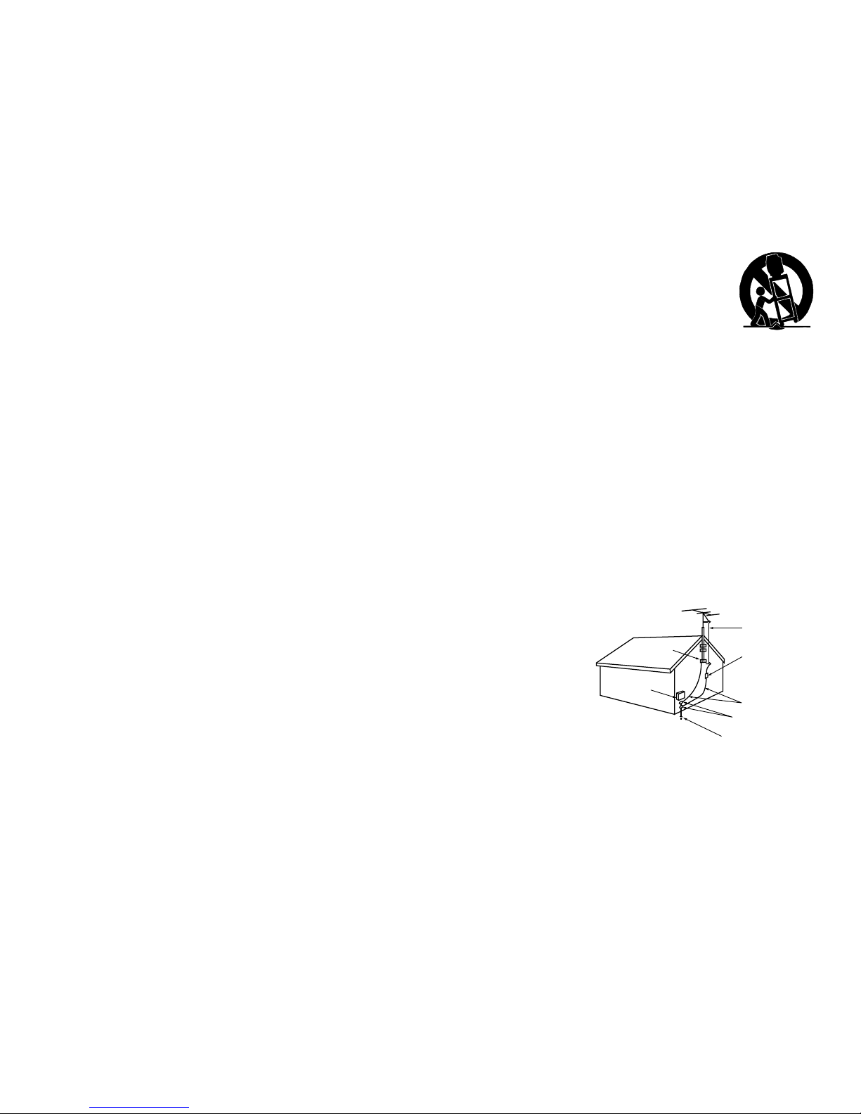
NOTE TO CATV SYSTEM INSTALLER:
THIS
REMINDER IS PROVIDED TO CALL THE CATV SYSTEM
INSTALLER’S ATTENTION TO ARTICLE 820-40 OF THE
NEC THAT PROVIDES GUIDELINES FOR THE PROPER
GROUNDING AND, IN PARTICULAR, SPECIFIES THAT
THE CABLE GROUND SHALL BE CONNECTED TO THE
GROUNDING SYSTEM OF THE BUILDING, AS CLOSE
TO THE POINT OF CABLE ENTRY AS PRACTICAL.
TV Software
Do not attempt to update the software of this TV with
software or USB drives not provided by or authorized by
Mitsubishi Digital Electronics America, Inc. Non-autho-
rized software may damage the TV and will not be covered
by the warranty.

Important Safeguards
Please read the following safeguards for your TV and retain for future reference. Always follow all warnings and instructions
marked on the television.
1. Read, Retain and Follow All Instructions. Read all safety and operating instructions before operating the TV. Retain the safety and operating
instructions for future reference. Follow all operating and use instructions.
2. Heed Warnings. Adhere to all warnings on the appliance and in the operating instructions.
3. Cleaning. Unplug the TV from the wall outlet before cleaning. Do not use liquid, abrasive or aerosol cleaners. Cleaners can permanently
damage the cabinet and screen. Use a lightly dampened cloth for cleaning.
4. Attachments and Equipment. Never add any attachments and/or equipment without approval of the manufacturer as such additions may
result in the risk of fire, electric shock or other personal injury.
5. Water and Moisture. Do not use the TV where contact with or immersion in water is possible. Do not use near bath tubs, wash bowls, kitchen
sinks, laundry tubs, in a wet basement, swimming pools, etc.
6. Accessories. Do not place the TV on an unstable cart, stand, tripod, or table. The TV may fall, causing serious injury to a
child, adult or pet and serious damage to the TV. Use only with a cart, stand, tripod, bracket or table recommended by the
manufacturer, or sold with the TV. Any mounting of the TV should follow the manufacturer’s instructions, and should use
mounting accessories recommended by the manufacturer.
An appliance and cart combination should be moved with care. Quick stops, excessive force, and uneven surfaces may cause
the appliance and cart combination to overturn.
7. Ventilation. Slots and openings in the cabinet are provided for ventilation and to ensure reliable operation of the TV and to protect it from
overheating. Do not block these openings or allow them to be obstructed by placing the TV on a bed, sofa, rug, or other similar surface. Nor
should it be placed over a radiator or heat register. If the TV is to be placed in a rack or bookcase, ensure that there is adequate ventilation and
that the manufacturer’s instructions have been adhered to.
8. Power Source. This TV should be operated only from the type of power source indicated on the marking label. If you are not sure of the type of
power supplied to your home, consult your appliance dealer or local power company.
9. Grounding or Polarization. This TV is equipped with a polarized alternating current line plug having one blade wider than the other. This plug
will fit into the power outlet only one way. This is a safety feature. If you are unable to insert the plug fully into the outlet, try reversing the plug.
If the plug should still fail to fit, contact your electrician to replace your obsolete outlet. Do not defeat the safety purpose of the polarized plug.
10. Power-Cord Protection. Power-supply cords should be routed so that they are not likely to be walked on or pinched by items placed upon or
against them, paying particular attention to cords at plugs, convenience receptacles, and the point where they exit from the TV.
11. Lightning. For added protection for this TV during a lightning storm, or when it is left unattended and unused for long period of time, unplug it
from the wall outlet and disconnect the antenna or cable system. This will prevent damage to the TV due to lightning and power-line surges.
12. Power Lines. An outside antenna system should not be located in the vicinity of overhead power lines or other electric light or power circuits,
or where it can fall into such power lines or circuits. When installing an outside antenna system, extreme care should be taken to keep from
touching such power lines or circuits as contact with them might be fatal.
13. Overloading. Do not overload wall outlets and extension cords as this can result in a risk of fire or
electric shock.
14. Object and Liquid Entry. Never push objects of any kind into this TV through openings as they
may touch dangerous voltage points or short-out parts that could result in fire or electric shock.
Never spill liquid of any kind on or into the TV.
15. Outdoor Antenna Grounding. If an outside antenna or cable system is connected to the TV, be
sure the antenna or cable system is grounded so as to provide some protection against voltage
surges and built-up static charges.
Article 810 of the National Electric Code, ANSI/NFPA No. 70-2002, provides information with
respect to proper grounding of the mast and supporting structure, grounding of the lead in wire to
an antenna discharge unit, size of grounding conductors, location of antenna discharge unit, con-
nection to grounding electrodes, and requirements for the grounding electrode.
16. Servicing. Do not attempt to service this TV yourself as opening or removing covers may expose you to dangerous voltage or other hazards.
Refer all servicing to qualified service personnel.
17. Damage Requiring Service. Unplug the TV from the wall outlet and refer servicing to qualified service personnel under the following
conditions:
(a) When the power-supply cord or plug is damaged.
(b) If liquid has been spilled, or objects have fallen into the TV.
(c) If the TV has been exposed to rain or water.
(d) If the TV does not operate normally by following the operating instructions, adjust only those controls that are covered by the operating
instructions as an improper adjustment of other controls may result in damage and will often require extensive work by a qualified techni-
cian to restore the TV to its normal operation.
(e) If the TV has been dropped or the cabinet has been damaged.
(f) When the TV exhibits a distinct change in performance - this indicates a need for service.
18. Replacement Parts. When replacement parts are required, be sure the service technician has used replacement parts specified by the
manufacturer or have the same characteristics as the original part. Unauthorized substitutions may result in fire, electric shock or other hazards.
19. Safety Check. Upon completion of any service or repair to the TV, ask the service technician to perform safety checks to determine that the TV
is in safe operating condition.
20. Heat. The product should be situated away from heat sources such as radiators, heat registers, stoves or other products (including amplifiers)
that produce heat.
AN T E N N A
LE AD IN W IR E
AN T E N N A
DI S C H AR G E UN IT
(N E C AR T I C L E 8 10- 20)
G R O U NDIN G
C O N DU C T O R S
(N E C AR T I C L E 8 10- 21)
G R O U ND C L AMP S
P OW E R S E R V IC E G R O U N DIN G
E L E C T R O DE S Y S T E M
(N E C AR T 250, P AR T H )
G R O U ND C L AMP
E L E C T R IC
S E R V IC E
E Q UIP ME N T
N E C — NA T IO N AL E L E C T R I C A L C O DE
E XAMP LE OF AN T E NNA G R OUNDING

6
Package Contents
Please take a moment to review the following list of
items to ensure that you have received everything.
Special Features of Your TV
Your new high-definition widescreen television has
many special features that make it the perfect center of
your home entertainment system, including:
1080p High-Definition DLP Display System
Your Mitsubishi HDTV uses Texas Instruments Digital
Light Processing™ technology for rear-projection TVs
to create the picture you see on screen. All images
are displayed at 1080p. The TV uses Plush 1080p®to
convert lower-resolution signals to 1080p for display.
The TV can also accept 1080p original signals and
maintain them at 1080p through all processing until
displayed.
16:9 Widescreen Picture Format
Enjoy a full theatrical experience in the comfort of your
home. View pictures as film directors intended them.
Digital TV broadcasts, DVDs and newer video game
consoles support this widescreen format.
Integrated HDTV Tuner
Your widescreen Mitsubishi HDTV has an internal HDTV
tuner able to receive both over-the-air HDTV broad-
casts (received via an antenna) and non-scrambled
digital cable broadcasts, including non-scrambled
HDTV cable programming.
High-Definition Video Inputs
Component Video Inputs. Also called Y/Pb/Pr
inputs, these inputs receive standard analog video
formats of 480i, 480p, 720p, and 1080i high-defini-
tion signals. This provides a high level of flexibility
when connecting DVD players/recorders, cable
boxes, and satellite receivers.
HDMI 1.3 Inputs. These inputs accept digital 480i,
480p, 720p, 1080i, and 1080p video signals plus
PCM digital stereo signals. The HDMI™ inputs can
also accept a variety of PC signals and resolutions.
These inputs are compatible with Deep Color and
x.v.Color.
Used with an adapter, these inputs also accept
compatible digital DVI video signals. HDMI
inputs provide additional high-performance, high-
definition connections for maximum flexibility in
your choice of home theater products. The HDMI
inputs are HDCP copy-protection compatible.
IEEE 1394 Digital Interfaces that receive and
send compressed digital signals, including high-
definition signals, along with digital audio and
control signals between devices such as the TV, a
digital cable box, an A/V disc, and a D-VHS digital
video recorder.
Easy Connect Auto Input Sensing
Easy Connect™ Auto Input Sensing automatically
recognizes when you plug in an input and prompts
you to assign a name to it. The TV ignores any unused
inputs, so the result is an uncluttered Input Selection
menu where you can easily find and select connected
devices by name.
Home Theater Control
NetCommand with IR Learning
Your Mitsubishi HDTV offers a new level of networking
that seamlessly integrates selected older A/V products
with new and future digital products. NetCommand®
supports IR (infrared) control of products such as
VCRs, DVD players, cable boxes, and satellite receiv-
ers. NetCommand can “learn” remote control signals
directly from many devices, allowing you to create a
customized NetCommand-controlled home-theater
system.
Television Overview
1
1. Remote Control
2. Two AA Batteries
3. Owner’s Guide
4. Quick Reference Guide
5. Quick Connect Guide
6. Product Registration Card
7. Four-Ended IR Emitter
8. TV Guide On Screen®
Interactive Program Guide
User’s Manual
9. Cleaning Cloth for Glossy
Surfaces (see instructions
under “Cleaning Recommen-
dations”).
AA
AA
2
7
1
9

1. Television Overview 7
TV Front Panel
A/V Reset
If you wish to reset the A/V (Audio/Video) settings back
to the factory defaults:
• To reset all settings at once, press
GUIDE
and
FORMAT
on the front panel at the same time.
• To reset the defaults for individual inputs, use the
Reset selection on the AV menu.
Front Panel Indicators and Power Button
1. POWER button. Turns TV on and off; works the
same as the
POWER
key on the remote control.
2. POWER/TIMER indicator. Lit when TV is
powered on; flashes when TV is powered off and
the auto-on TV Timer is set;
blinks rapidly when
TV is first plugged into an AC outlet.
3. STATUS
indicator. Off during normal TV opera-
tion.
4. LAMP indicator shows lamp condition (usually off
during normal TV operation).
See the next page for more on front-panel indicators.
Control Panel
Buttons on the front
control panel duplicate
commonly used keys on
the remote control. The
upper labels show control
functions when no TV
menus are displayed; the
lower labels indicate func-
tions when TV menus are displayed or when a special
function has been activated. See chapter 4, “TV Opera-
tion and Features,” for the functions of these buttons.
Front Inputs
• INPUT/COMPONENT 3
is an easily accessible set of
input jacks for a camcorder, game, or other audio/
video device.
• A USB photo port lets you view JPEG images.
• A convenient fourth HDMI input is provided. If
connecting a DVI device to the front HDMI jack,
connect analog audio cables to the
INPUT 3
L
and
R
AUDIO
jacks.
I
N
P
U
T
L-AUDIO-R VIDEO/Y Pb Pr 3USB
HDMI 4
DVI AUDIO
Front inputs. When using a standard video device, connect
the single (yellow) video cable to the
VIDEO/Y
jack
.
Flip down cover to
use buttons and
inputs on the front
panel.
System Reset Button
If the TV fails to respond to the
remote control, front panel controls,
or will not power on/off, press the
SYSTEM RESET
button on the front panel.
The green LED on the front panel will flash quickly for
about one minute. When the green LED stops flashing,
you may turn on the TV. Recent setting changes you
made before using
SYSTEM RESET
may be lost.
Front Control Panel. Buttons on the
front panel duplicate some keys on
the remote control.
VOL
ADJ ADJ
CH FORMAT MENU GUIDE INPUT SYSTEM
RESET
ENTER MENU CANCEL
VOL
ADJ ADJ
CH FORMAT MENU GUIDE INPUT SYSTEM
RESET
ENTER MENU CANCEL
4:45&.
3&4&5
Indicator LED lights and
POWER
button
NetCommand for HDMI Devices
Some newer HDMI devices may be compatible with
the TV’s NetCommand for HDMI feature. Compatible
devices can receive control signals through the HDMI
connection. The TV’s remote control may be able to
operate some functions of these devices without any
further setup.
TV Guide On Screen®Interactive Program
Guide System
An eight-day on-screen program guide for cable and
over-the-air reception. This subscription-free guide
system lists regular, digital, and high-definition pro-
gramming. Note that when the system is first set up, it
may take up to 24 hours to begin to receive TV program
listings and then it may take up to one week to receive
all eight days of TV program listings.
13
4 2

81. Television Overview
Front-Panel Indicators
LAMP Indicator
LED Color TV Condition Additional Information
None Normal TV on or standby condition. Normal operation.
Green TV just powered off and lamp is
cooling.
Starts to blink 30 seconds after turning off TV. TV can be turned
back on before blinking starts or after blinking stops, but not
while the indicator is blinking. Normal operation.
Yellow 1. Lamp access door is open or
not secure.
TV will not operate until lamp access door is secure. See
Appendix B for installation information.
2. No lamp installed. TV will not operate without a lamp. See Appendix B for installa-
tion information.
Red Lamp no longer illuminates and has
reached the end of the lamp life.
Replace the lamp. The TV will not operate when the lamp no
longer illuminates. See Appendix B for installation information.
Off Steady On Slow Blinking Fast Blinking
STATUS Indicator
LED Color TV Condition Additional Information
None Normal TV on or standby condition. Normal operation.
Yellow TV is too hot.
The TV will display a warning message and shut off if it overheats.
• Ambient room temperature may be too high. Turn off the TV
and wait until the room temperature drops.
• Clear blocked air vents. Ensure at least a four-inch clear-
ance on all sides of the TV.
• Clean the lamp-cartridge air filter. See Appendix B.
Red
TV may require service.
Turn off the TV and unplug the set from the AC power source.
Wait one minute and then plug the set back in. See Appendix E.
If the LED is still on, contact your dealer or a Mitsubishi
Authorized Service Center. Go to www.mitsubishi-tv.com or call
1-800-332-2119 to receive Authorized Service Center information.
POWER/TIMER Indicator
LED Color TV Condition Additional Information
None TV is powered off. Normal operation.
Green TV is powered on. Normal operation.
Green TV powered off, auto-on timer is set. Normal operation. TV can be turned on at any time.
Green 1. TV just plugged into AC outlet. Wait approximately one minute for blinking to stop before
turning on. Normal operation.
2.
AC just restored after power failure.
3. TV rebooting after System Reset
used.
4. TV rebooting after power fluc-
tuation or receiving abnormal
digital signals from a digital
channel or digital device.
5. You have begun the procedure
to update software from an
authorized flash memory device.

1. Television Overview 9
TV Back Panel
1. ANT 1/MAIN, ANT 2/AUX (Antenna)
If you are connecting an antenna or direct cable without
a cable box, connect the main antenna or cable source
to
ANT 1/MAIN
. Use
ANT 2/AUX
for a second source.
ANT 1/MAIN
and
ANT 2/AUX
can each receive digital
and analog over-the-air channels from a VHF/UHF
antenna or non-scrambled digital/analog cable source.
2. DIGITAL AUDIO OUTPUT
This output sends Dolby Digital or PCM digital audio to
your digital A/V surround sound receiver. Analog audio
from analog channels and devices is converted by the TV
to PCM digital audio. If you have a digital A/V receiver,
in most cases this is the only audio connection needed
between the TV and your A/V receiver.
3. RS-232C
Use the RS-232C interface to receive control signals
from compatible home-theater control devices.
4. IR Emitter NetCommand
IR Emitters connected to this jack are used by the TV’s
NetCommand system to control external IR remote
controlled analog devices such as cable boxes, VCRs,
DVDs, satellite receivers and audio receivers.
5. IEEE 1394 (also known as Firewire®)
These jacks allow the TV to connect to external IEEE
1394 digital products by means of a single cable. See
chapter 6, “NetCommand” for information regarding
IEEE 1394 connections and recording.
6. INPUT (audio and video; front and rear)
INPUT
jacks can be used to connect a VCR, Super VHS
(S-VHS) VCR, DVD player, standard satellite receiver, or
other A/V device to the TV. The
INPUT
groups on the
back of the TV consist of jacks for composite video,
S-Video, and analog stereo audio. Note that when you
connect to the S-video jack, the composite video jack
is automatically disabled.
INPUT 3
is a third set of com-
posite video and stereo audio jacks located on the front
of the TV for convenience.
COMPONENT 1
Y Pb Pr (480i/480p/720p/1080i)
COMPONENT 2
RECORD
OUTPUT
OUTPUT
DIGITAL
IR EMITTER
NetCommand
RS-232C
AUDIO
INPUT 1
INPUT 2
HDMI
VIDEO: 480i / 480p / 720p /
1080i / 1080p
W-SVGA, XGA, W-XGA,
AUDIO: LINEAR PCM
PC: VGA, W-VGA, SVGA,
1 (LEFT) ,, 2 (MIDDLE) 3 (RIGHT)
DVI / PC
VIDEO
AUDIO-
AUDIO-
RIGHT
LEFT
L (MONO)
INPUT
AVR
AUDIO
AUDIO
OUTPUT
S-VIDEO VIDEO - AUDIO - R
L (MONO)- AUDIO - R
Y Pb Pr
EMITTER
3D GLASSES
SXGA / 720p / 1080p
IEEE 1394
ANT 2 / AUX
ANT 1 / MAIN
1 7 8
2 3 4 5 6
91112 10

10 1. Television Overview
7. HDMI™Inputs
The HDMI 1.3 (High Definition Multimedia Interface) sup-
ports uncompressed standard and high-definition digital
video formats and PCM digital stereo audio format.
Use the HDMI inputs to connect to CEA-861 HDMI com-
pliant devices such as a high-definition receiver or DVD
player. These inputs support 480i, 480p, 720p, 1080i,
and 1080p video formats.
Mitsubishi recommends you use category 2 HDMI cables
to connect HDMI 1.3 source devices. High-speed cat-
egory 2 cables bring you the full benefits of Deep Color
and x.v.Color.
These inputs can also accept digital DVI video inputs.
To connect a DVI input, use an HDMI-to-DVI adapter or
cable plus analog audio cables. Connect the analog
audio cables to the
DVI/PC AUDIO INPUT
on the TV to
receive left and right stereo audio from your DVI device.
The TV’s HDMI inputs are compatible with many DVI-D
and HDMI computer video signals. See chapter 2, “TV
Setup” and Appendix A for additional information on PC
compatibility.
These inputs are HDCP (High-Bandwidth Digital Copy
Protection) compliant.
These inputs are certified for proper
interoperability with other products certified by Simplay™.
HDMI Cable Categories
HDMI cables are available as Category 1 and
Category 2 versions.
• Category 2 Cables.
Newer, HDMI 1.3-com-
pliant DVD players, video games, and set-top
boxes require Category 2 cables. Use category
2 cables for these high-speed HD signals car-
rying extended color encodings (i.e., 30 or more
bits, also called Deep Color). Category 2 cables
are also suitable for standard HDTV signals.
• Category 1 Cables. Unmarked cables are
category 1 cables and are suitable for standard
HDTV signals.
8. AVR AUDIO OUTPUT
Use
AVR AUDIO OUTPUT
to send analog audio of the
program currently shown on the screen to an A/V sur-
round sound receiver or stereo system. Digital audio
from digital channels and HDMI devices is converted to
analog audio by the TV. If using an analog A/V receiver
or stereo system, this is the only audio connection
needed between it and the TV.
TV Back Panel, continued
9. DVI/PC AUDIO INPUT
Use the
DVI/PC AUDIO INPUT
when connecting a DVI
device to one of the TV’s HDMI inputs using a DVI-to-
HDMI cable. These jacks allow you to send left and
right analog audio from your computer or other DVI
device to the TV.
10. COMPONENT (audio and video; front
and rear)
Y Pb Pr (480i/480p/720p/1080i)
Use these jacks to connect devices with component
video outputs, such as DVD players, external HDTV
receivers, or compatible video game systems. A third
set of component jacks is located on the front of the
TV and shares the left/right audio jacks and
VIDEO/Y
jack with the
INPUT 3
composite input. See Appendix A
specifications for signal compatibility.
11. RECORD OUTPUT
Use these composite video and left/right audio jacks
to send analog video and audio signals to an external
recording device such as a VCR. To make recordings
from this output, the TV must be in normal full-
screen mode rather than in Split Screen mode.
• You can watch another device while recording,
but not another channel.
• From this output you can record audio and
video signals from
ANT 1
,
ANT 2
,
INPUT 1-3
, and
IEEE 1394 devices.
• Digital signals from
ANT 1
,
ANT 2
, and IEEE
1394 devices are converted to analog video and
audio signals.
• Some signals cannot be recorded because of
copy-protection flags in the content.
12. 3D GLASSES EMITTER
The
3D GLASSES EMITTER
jack is in place for future
gaming devices equipped with FX gaming 3D and dual-
view features. Use this jack to connect a special IR
emitter (supplied with the 3D glasses) that will synchro-
nize your 3D glasses with the screen display.

11
TV Set-Up
Getting Started
1. Review the important safety, installation, and oper-
ating information at the beginning of this book.
2. Choose a location for your TV.
• Allow at least four inches of space on all sides
of the TV to help prevent overheating. Over-
heating may cause premature failure of the TV
as well as shortened lamp life.
• Avoid locations where light may reflect off the
screen.
• See the stand requirements under “Important
Information About Your TV.”
3. Install the batteries in the remote control. See the
following page. See chapter 4, “TV Operation and
Features” for more on use of the remote control.
4. Plug your TV into a power outlet. The green LED on
the front of the TV will start blinking rapidly. After
the green LED stops blinking, press the
POWER
key to
power on the TV.
5. When the Welcome screen appears the first time
you power on the TV, select a language for TV
menus. You can later change the language through
the Setup menu.
6. Connect your audio/video (A/V) devices to the TV
and perform initial setup.
• See chapter 3, “TV Connections” for connec-
tion diagrams.
• See the following pages for initial TV setup and
use of the Auto Input Sensing feature.
• See chapter 6, “NetCommand,” to perform
NetCommand IR “learning” for control of your
home theater.
7. Mitsubishi recommends you perform a channel
scan for channels received on
ANT 1
and
ANT 2
.
See “Initial TV Setup” on the following pages.
8.
You can now start watching TV or you can perform
additional setup and customization through the TV
menus.
Guidelines for Setting Up and Using Your New Widescreen TV
TV Operation
1. Review chapter 4, “TV Operation and Features,” for
TV features including:
• Input Selection (viewing source). Select a
connected program source to watch, such as a
VCR, DVD player, or antenna. Press
INPUT
on the
remote control to select from icons for the TV
inputs. See “Choosing a Viewing Source.”
• ChannelView™/TV Guide On Screen®.Press
GUIDE
to see channel listings for programs on
ANT 1
and
ANT 2
. To override ChannelView
and use the TV Guide On Screen system, see
Chapter 5, “TV Menu Settings” and the Inputs
menu Guide options.
• Picture Formats. Press
FORMAT
to cycle through
picture sizes and shapes to find the one best
suited to the current program. See “TV Signals
and Display Formats.”
2. To understand use of the Input Selection menu
with NetCommand-controlled devices, see “Using
NetCommand.”
3. To view JPEG photo files on the TV, see “Viewing
Camera Files.”
Additional TV Setup
1. Review chapter 5, “TV Menu Settings,” to custom-
ize TV operation. Press the
MENU
key to enter the
menu system. Some examples of settings you may
wish to change include:
• Fav. Use an on-screen menu to create custom
lists of your favorite channels from
ANT 1
and
ANT 2
. See Setup > Edit.
• Order. Rearrange the device icons in the Input
Selection menu to put frequently used icons
near the front. See Inputs > Order.
• Name. Change the device names that appear
in the Input Selection menu. See the Inputs
menu Name options.
• TV Guide On Screen. Set up and enable the
TV Guide On Screen system. See the Inputs >
Guide menu.
2

12 2. TV Setup
• Parental Locks. Restrict TV viewing by
program rating, by channel, or by time of day.
You can also disable the front-panel buttons
if you have small children. See the Lock >
Parent menu, the Lock > Front Panel menu,
and Setup > Edit > Lock.
• Video Settings. Change video adjustments to
get the best picture for your viewing conditions.
See “AV Menu.”
Note: You may wish to change the Picture Mode from
the default Brilliant to either Bright or Natural,
which are suitable for most home viewing.
2. To program the remote control to operate A/V
devices not under NetCommand control, see
Appendix D, “Programming the Remote Control.”
TV Care
• Lamp Cartridge. When the lamp cartridge
needs replacement, replace the lamp yourself
and save the cost of a service call. See
Appendix B for instructions.
• General Cleaning. See the cleaning recom-
mendations under “Important Information
About Your TV.”
Assistance
• For troubleshooting, service, and product
support, see Appendix E.
• For warranty information, see the TV warranty
in the back of this book.
Installing the Remote Control Batteries
1. Remove the remote control’s back cover by gently
pressing in the tab and lifting off the cover.
2. Load the batteries, making sure the polarities (+)
and (-) are correct. For best results, insert the
negative (-) end first.
3. Snap the cover back in place.
2
1
The remote control requires two AA alkaline batteries.
Turning the TV On or Off
To turn the TV on or off, point the remote control
at the front of the TV and press the
POWER
button.
Alternatively, press the
POWER
button on the front
panel of the TV.
If You Turn Off the TV by Mistake
1. Press
POWER
again within about 30 seconds,
while the lamp is still hot, to have the TV come
back on immediately.
2. If the
LAMP
indicator starts blinking (about 30
seconds after you shut off power), wait about
one minute for the
LAMP
indicator to stop
blinking and press
POWER
to turn the TV on
again.
When You First Power On the TV
Choosing a Language for Menus
1. Power on the TV for the first time.
2. Press to select either English or Spanish
for all menus. You can later change the language
selection through the Setup menu Language
option.
When you first power on the TV, the Welcome screen lets
you change the menu language.
Initial TV Setup
Use the Setup menu for basic TV setup options.
1. Press
MENU
to open the Main menu.
2. Press to highlight the Setup icon and display the
Setup menu.
Setup menu highlighted in TV Main menu

2. TV Setup 13
Change the Menu Language
Choose to display on-screen menus in either English or
Spanish (Español).
Select a menu language in the Setup menu.
1. With the Setup menu displayed, press to high-
light the Language icon.
2. Press to highlight either English or Spanish.
3. Press
MENU
to return the highlight to the top row of
icons.
Memorize Channels
For ANT 1/MAIN and ANT 2/AUX
To start channel memorization
1. With the Setup menu displayed, press to high-
light the Scan icon.
2. Press to highlight an input selection based on
your connections:
Input Condition
Ant 1 Air
Ant 2 Air
When connected to an indoor or
outdoor antenna
Ant 1 Cable
Ant 2 Cable
When connected to direct cable (no
cable box)
3. Press to highlight the on-screen START button.
4. Press
ENTER
to start automatic channel memoriza-
tion.
To stop channel memorization before
completion, press
CANCEL
.
Start channel memorization from the Setup menu.
Additional TV Setup Using the Setup Menu
See chapter 5, “TV Menu Settings,” to:
• Edit channel options
• Set the TV clock
• Set the TV Timer
• Select an Energy Mode to manage power use while
the TV is off.
• Select a lamp brightness mode
Initial TV Setup, continued
5. When memorization is complete you can:
• Press
MENU
once to return to the top row of icons.
• Press
MENU
again to return to the Main menu.
• Press
EXIT
to watch TV.
After channels have been memorized:
• To tune to memorized channels, press
CH
/
while watching TV on the
ANT 1
or
ANT 2
inputs.
• Use the Setup > Edit menu for additional channel
options, such as adding or deleting channels from
memory, naming channels, and saving favorite
channels in custom memory banks.
Setting Up TV Inputs
When You First Connect a Device
This TV’s Easy Connect™ Auto Input Sensing feature
detects most connections automatically. When you
first connect a device, the TV will:
a. detect the connected device
b. prompt you to identify the device type
c. prompt you to perform NetCommand set-up for
the device, if available
d. repeat these steps for any additional newly
detected devices
The tables below state which connections trigger Auto
Input Sensing.
Auto Detection Active No Auto Detection
INPUT
video jacks
ANT 1
and
ANT 2
COMPONENT
video jacks
HDMI
*
DIGITAL AUDIO OUT
AVR AUDIO OUTPUT
(analog)
USB
(USB photo port on front)
*
If the device is powered off when connected, detec-
tion occurs when the device is next powered on.
Note: For connection and setup of a personal com-
puter, see the information later in this chapter.

14 2. TV Setup
1. See chapter 3, “TV Connections,” for recommen-
dations on connecting your devices.
2. Connect your devices to the TV, making note of
which TV input is used for each device.
The TV and the devices can be either on or off
when connecting.
First select a
device type.
Next perform
IR “learning.”
Auto Input Sensing screen for most device types.
3. Power on the TV if not already on. When the TV
detects a connection, the Auto Input Sensing
screen opens.
• Most Device Types: Specify the device
type and then, if desired, proceed directly to
NetCommand setup.
a. In the Auto Input Sensing screen, press
to move through the device list to select
the device type connected to the input.
The device type you select here will appear
in the Input Selection menu.
b. You can perform NetCommand IR “learn-
ing” now or at a later time. To perform now,
highlight the Learn icon and press
ENTER
.
See chapter 6, “NetCommand” for more.
• A/V Receiver: The TV can detect audio con-
nections on the
DIGITAL AUDIO OUT
jack and
the right (red) analog
AVR AUDIO OUTPUT
jack.
Note for Analog A/V Receivers: When you
disconnect an analog A/V receiver, be sure to
change the Speakers setting manually to TV to
hear sound from the TV speakers.
You can perform “learning” for the A/V receiver
now or at a later time. To perform now, highlight
th
e Learn icon in the Auto Output Sensing
screen and press
ENTER
. See chapter 6,
“NetCommand” for more.
• HDMI Devices Compatible with the TV’s
NetCommand for HDMI Feature: Compatible
HDMI devices are often recognized automati-
cally by the TV. The TV’s remote control may
operate some device functions without further
setup. You can add more control functions if
desired. Program the TV’s remote control or
Setting Up TV Inputs, continued perform NetCommand IR “learning” to add
functions.
4 Press
EXIT
to close the Auto Input Sensing screen.
The TV will then display the Auto Input Sensing
screen for the next connection it finds.
More About Auto Input Sensing
• Choose a different name for each input.
• Antenna inputs (
ANT 1/ANT 2
) are never detected,
although you can turn off unused antenna inputs in
the Inputs > Name menu.
• You can change the device type at a later time
using the Inputs > Name menu. Any “learned”
NetCommand IR codes will be erased, however.
• If you wish to change devices on an HDMI input:
1. Disconnect the HDMI device.
2. Turn off the HDMI input in the Inputs > Name
menu.
3. Connect the new device and the Auto Input
Sensing screen will display. If you want the
device under NetCommand IR control, perform
NetCommand “learning” for the new device.
Controlling A/V Receiver Sound Volume
Although the TV detects when you connect an A/V
receiver, you must use one of the methods below to
control sound volume from the A/V receiver.
With a Standard TV Setup
• Recommended Method: Program the TV’s remote
control for your A/V receiver and enable the Audio
Lock feature. See Appendix D, “Programming the
Remote Control.”
• Program the TV’s remote control for your A/V
receiver and set the TV remote’s slide switch to
the
AUDIO
position to control volume. Set the switch
back to the
TV
position to control the TV.
• Use the remote control that came with the A/V
receiver.
With NetCommand Control of an A/V Receiver
• Set up NetCommand control of the A/V receiver’s
volume functions in the Inputs > AVR menu. The
TV’s remote will then automatically control A/V
receiver volume. See chapter 6, “NetCommand.”
• Use any of the methods described for the standard
TV setup.

2. TV Setup 15
Connecting a Computer to the TV
Use one of the connection methods listed below based
on your computer’s video output.
Computer
Video Output
Video Connection Audio
Connection
Digital DVI DVI-to-HDMI cable
or an HDMI cable
with an HDMI-to-
DVI adapter
Stereo audio
cables
Note: If the computer’s audio output
is a single mini jack, a mini audio-to-
RCA-male “Y” adapter cable is also
required.
HDMI HDMI-to-HDMI
cable
No additional
audio connec-
tion is required.
IMPORTANT
This TV accepts digital computer signals only.
1. See the TV specifications in Appendix A to confirm
that your computer signal is compatible with the TV.
2. Connect the computer’s digital signal output to one
of the TV’s
HDMI
jacks. See the connection dia-
grams for the method suited to your equipment.
3. Connect the computer’s audio output using one of
these options:
• For digital DVI signals, connect analog left/right
audio to the TV’s
DVI/PC AUDIO INPUT
jack.
• For HDMI signals, no additional audio connec-
tion is required.
4. Power on the TV and computer. The TV will detect
the connection and display the Auto Input Sensing
screen.
5. In the Auto Input Sensing screen, press to
highlight PC in the list of device types. You can
change the type at a later time using the Inputs >
Name menu.
6. Press
EXIT
to close the Auto Input Sensing screen.
)%.*UP%7*$BCMF
COMPONENT 1
Y Pb Pr (480i/480p/720p/1080i)
COMPONENT 2
RECORD
OUTPUT
OUTPUT
DIGITAL
IR EMITTER
NetCommand
RS-232C
ANT 1 /
MAIN
ANT 2 /
AUX
AUDIO
INPUT 1
INPUT 2
HDMI
VIDEO: 480i / 480p / 720p /
1080i / 1080p
W-SVGA, XGA, W-XGA,
AUDIO: LINEAR PCM
PC: VGA, W-VGA, SVGA,
1 (LEFT) ,, 2 (MIDDLE) 3 (RIGHT)
DVI / PC
VIDEO
AUDIO-
AUDIO-
RIGHT
L (MONO)
INPUT
AVR
AUDIO
AUDIO
OUTPUT
S-VIDEO VIDEO - AUDIO - R
L (MONO)- AUDIO - R
Y Pb Pr
EMITTER
3D GLASSES
IEEE 1394
SXGA / 720p / 1080p
LEFT
DVI / PC
INPUT
AUDIO
4UFSFP"VEJP$BCMF
A DVI connection from a personal computer requires a
separate audio connection. Computer connected to the
TV back panel (above) and TV front panel (below).
I
N
P
U
T
L-AUDIO-R VIDEO/Y Pb Pr 3USB
HDMI 4
DVI AUDIO HDMI 4
L-AUDIO-R
4UFSFP"VEJP$BCMF
57'SPOU1BOFM 1FSTPOBM$PNVUFS
XJUI%7*0VUQVU
)%.*UP%7*
$BCMF
1FSTPOBM
$PNQVUFSXJUI
)%.*0VUQVU
COMPONENT 1
Y Pb Pr (480i/480p/720p/1080i)
COMPONENT 2
RECORD
OUTPUT
OUTPUT
DIGITAL
IR EMITTER
NetCommand
RS-232C
ANT 1 /
MAIN
ANT 2 /
AUX
AUDIO
INPUT 1
INPUT 2
HDMI
VIDEO: 480i / 480p / 720p /
1080i / 1080p
W-SVGA, XGA, W-XGA,
AUDIO: LINEAR PCM
PC: VGA, W-VGA, SVGA,
1 (LEFT) ,, 2 (MIDDLE) 3 (RIGHT)
DVI / PC
VIDEO
AUDIO-
AUDIO-
RIGHT
L (MONO)
INPUT
AVR
AUDIO
AUDIO
OUTPUT
S-VIDEO VIDEO - AUDIO - R
L (MONO)- AUDIO - R
Y Pb Pr
EMITTER
3D GLASSES
IEEE 1394
LEFT
SXGA / 720p / 1080p
DVI / PC
INPUT
AUDIO
57#BDL1BOFM
An HDMI-to-HDMI connection carries all video and
audio on a single cable.
Note: If your computer provides digital audio
output (coaxial or digital), you can connect it
directly to a digital A/V receiver and bypass
the TV.
Using the TV with a Personal Computer

16 2. TV Setup
Tip:
Set the computer’s screen saver to display a
pattern after several minutes of inactivity. This acts
as a reminder that the TV is powered on and the
lamp is in use. The lamp is in use whenever the TV
is powered on, even if the screen appears dark.
Computer Video Adjustments
1. Power on the computer if it is not already on.
2. Select PC from the Input Selection menu. To do
this, press
INPUT
to open the Input Selection menu,
move the highlight to the PC icon, and press
ENTER.
3. Working from the computer, change the resolution
of the computer image. View the computer image
on the TV and maximize the computer resolution
while maintaining a suitable aspect ratio for the
image.
4. Perform TV video adjustments. Press
VIDEO
repeatedly to access video-
adjustment options. The following
additional adjustments are available
for computer video:
Horiz Position (Horizontal Position).
Manually adjust the horizontal
position.
Vert Position (Vertical Position).
Manually adjust the vertical position.
5. Press
FORMAT
repeatedly to find the
picture format best suited to the
image. See the chart on this page
showing how different computer reso-
lutions are displayed on the TV.
Image Resolution
Your Mitsubishi TV can display resolutions
from standard VGA (640 x 480) through
1920 x 1080 signals at a refresh rate of 60
Hz. The resolution of 1920 x 1080 is sup-
ported at refresh rates of 24, 30, and 60
Hz. See Appendix A in this book for more
on compatible screen resolutions.
In most cases, the computer will select the
best resolution match to display on the TV.
You can override this setting if you wish.
Refer to your computer operating system’s
instructions for information on changing
the screen resolution.
You may need to restart the computer for
changes to take effect.
Using the TV with a Personal Computer
Computer Display Formats
Press the
FORMAT
key repeatedly to cycle through the TV displays avail-
able for your computer’s video signal.
Computer Signal
As Displayed on TV Screen
Original Format 4 X 3
Standard
16 X 9
Standard Zoom
VGA
640 X 480
WVGA
848 X 480
SVGA
800 X 600
WSVGA
1064 X 600
Original Format Standard Zoom
XGA
1024 X 768
PC 720p
1280 X 720
WXGA
1360 X 768
SXGA
1280 X 1024
Original Format Standard Reduce
PC 1080p
1920 X 1080
Distortion in Computer Images
Computer images may show
distortion when viewed on the TV,
e.g., lines that should be straight may
appear slightly curved.

17
3TV Connections
-
"6%*0
3
: 1C 1S
COMPONENT 1
Y Pb Pr (480i/480p/720p/1080i)
COMPONENT 2
RECORD
OUTPUT
OUTPUT
DIGITAL
IR EMITTER
NetCommand
RS-232C
ANT 1 /
MAIN
ANT 2 /
AUX
AUDIO
INPUT 1
INPUT 2
HDMI
VIDEO: 480i / 480p / 720p /
1080i / 1080p
W-SVGA, XGA, W-XGA,
AUDIO: LINEAR PCM
PC: VGA, W-VGA, SVGA,
1 (LEFT) ,, 2 (MIDDLE) 3 (RIGHT)
DVI / PC
VIDEO
AUDIO-
AUDIO-
RIGHT
L (MONO)
INPUT
AVR
AUDIO
AUDIO
OUTPUT
S-VIDEO VIDEO - AUDIO - R
L (MONO)- AUDIO - R
Y Pb Pr
EMITTER
3D GLASSES
IEEE 1394
LEFT
SXGA / 720p / 1080p
COMPONENT 1
$"#-&*/PS
4"5&--*5&*/
*ODPNJOHGSPN
$BCMF4FSWJDFPS
4BUFMMJUF%JTI
57
$BCMF#PY
PS4BUFMMJUF
3FDFJWFS
Figure 1. Connecting an external HDTV receiver with
component video connections
Auto Input Sensing
The TV’s Auto Input Sensing feature automatically rec-
ognizes most connections and prompts you to identify
the type of device connected. See chapter 2, “TV
Setup,” for more on Auto Input Sensing.
Connection Types
Review the connection types available on your input
devices and use connections that will give the best
video quality. For example, choose HDMI over compo-
nent video, and choose component video over S-video
or composite video.
Picture Quality
For best picture quality, route signals directly from
the input device to the TV; avoid routing video signals
through an A/V receiver, for example.
If your cable box or satellite receiver has an HDMI
output, use the connections for HDMI devices
described later in this chapter.
Required: RCA component video cables, left/right
analog stereo audio cables.
1. Connect the cable from the outside cable or satel-
lite service to
CABLE IN
or
SATELLITE IN
on the
cable box or satellite receiver. See your device’s
owner’s guide for instructions and cable compat-
ibility.
2. Connect RCA-type cables from the
Y Pb Pr
outputs
on the HDTV cable box or satellite receiver to
COMPONENT
on the TV back panel, matching the
colored green, blue, and red connections.
3. Connect left (white) and right (red) audio cables
from the HDTV cable box or satellite receiver to
COMPONENT
AUDIO L (MONO)
and
R
on the TV
back panel.
Note:
To hear digital surround sound, connect the digital
audio output from your cable box or satellite re-
ceiver directly to your digital A/V receiver.
Sound Quality
For best surround sound audio quality, route audio
signals from the input device directly to your A/V
receiver or sound system whenever possible.
IMPORTANT
Accessory items such as cables, adapters,
splitters, or combiners required for TV
connections are not supplied with the TV.
These items are available at many electronics
stores.
Before you Begin
HDTV Cable Box or Satellite Receiver with Component Video

18 3. TV Connections
H
DMI Device (Cable Box, Satellite
Receiver, DVD Player, or Other Device
)
Required: HDMI-to-HDMI cable.
Connect an HDMI cable from the TV back panel to the
HDMI device output. HDMI devices provide video and
audio through the single cable.
Mitsubishi recommends you use category 2 HDMI
cables to connect HDMI 1.3 source devices. High-
speed category 2 cables bring you the full benefits of
Deep Color and x.v.Color. See chapter 1, “TV Overview,”
for more on HDMI cable types.
COMPONENT 1
Y Pb Pr (480i/480p/720p/1080i)
COMPONENT 2
RECORD
OUTPUT
OUTPUT
DIGITAL
IR EMITTER
NetCommand
RS-232C
ANT 1 /
MAIN
ANT 2 /
AUX
AUDIO
INPUT 1
INPUT 2
HDMI
VIDEO: 480i / 480p / 720p /
1080i / 1080p
W-SVGA, XGA, W-XGA,
AUDIO: LINEAR PCM
PC: VGA, W-VGA, SVGA,
1 (LEFT) ,, 2 (MIDDLE) 3 (RIGHT)
DVI / PC
VIDEO
AUDIO-
AUDIO-
RIGHT
LEFT
L (MONO)
INPUT
AVR
AUDIO
AUDIO
OUTPUT
S-VIDEO VIDEO - AUDIO - R
L (MONO)- AUDIO - R
Y Pb Pr
EMITTER
3D GLASSES
SXGA / 720p / 1080p
IEEE 1394
)%.*%FWJDF
57#BDL1BOFM
Figure 2. Connecting an HDMI device.
Note:
HDMI inputs are certified for proper
interoperability with other products certified by
Simplay™.
Standard Cable Box, Satellite Receiver,
or Other Device with S-Video
Required: S-Video cable and left/right analog stereo
audio cables.
1. Connect the cable from the outside cable or satel-
lite service to
CABLE IN
or
SATELLITE IN
on the
cable box or satellite receiver.
2. Connect an S-Video cable from
S-VIDEO OUT
on
the cable box or satellite receiver back panel to
INPUT S-VIDEO
on the TV back panel.
3. Connect left (white) and right (red) audio cables
from
AUDIO OUT
on the cable box or satellite
receiver to
INPUT AUDIO L (MONO)
and
R
on the TV
back panel.
Note: Refer to the cable box or satellite receiver
Owner’s Guide for cable or dish antenna con-
nections to the receiver.
"6%*0065
7*%&0065
COMPONENT 1
Y Pb Pr (480i/480p/720p/1080i)
COMPONENT 2
RECORD
OUTPUT
OUTPUT
DIGITAL
IR EMITTER
NetCommand
RS-232C
ANT 1 /
MAIN
ANT 2 /
AUX
AUDIO
INPUT 1
INPUT 2
HDMI
VIDEO: 480i / 480p / 720p /
1080i / 1080p
W-SVGA, XGA, W-XGA,
AUDIO: LINEAR PCM
PC: VGA, W-VGA, SVGA,
1 (LEFT) ,, 2 (MIDDLE) 3 (RIGHT)
DVI / PC
VIDEO
AUDIO-
AUDIO-
RIGHT
LEFT
L (MONO)
INPUT
AVR
AUDIO
AUDIO
OUTPUT
S-VIDEO VIDEO - AUDIO - R
L (MONO)- AUDIO - R
Y Pb Pr
EMITTER
3D GLASSES
SXGA / 720p / 1080p
IEEE 1394 INPUT 2
L (MONO)
S-VIDEO VIDEO - AUDIO - R
$"#-&*/PS
4"5&--*5&*/
"OZ47JEFP%FWJDF
57#BDL1BOFM
*ODPNJOH
$BCMFGSPN
8BMM
Figure 3. Connecting a device with S-Video
IMPORTANT
HDMI and Audio Signals
• Digital Surround Sound: The TV’s HDMI
inputs can receive digital stereo audio
signals only. To hear digital surround
sound from an HDMI device, connect the
device’s digital audio output directly to your
A/V receiver. See the Owner’s Guides for
those devices for instructions.
• A/V Receiver with HDMI. If your A/V
receiver has an HDMI input, use the audio
connections described in “A/V Receiver
(Sound System)” instead.

3. TV Connections 19
Wall Outlet Cable (no cable box)
It is very important to connect the incoming cable for
your primary viewing source to
ANT 1/MAIN
.
1. Connect the primary incoming coaxial lead cable to
ANT 1/MAIN
on the TV back panel.
2. For an optional secondary antenna source, connect
an antenna (or cable) to
ANT 2/AUX
.
COMPONENT 1
Y Pb Pr (480i/480p/720p/1080i)
COMPONENT 2
RECORD
OUTPUT
OUTPUT
DIGITAL
IR EMITTER
NetCommand
RS-232C
AUDIO
INPUT 1
INPUT 2
HDMI
VIDEO: 480i / 480p / 720p /
1080i / 1080p
W-SVGA, XGA, W-XGA,
AUDIO: LINEAR PCM
PC: VGA, W-VGA, SVGA,
1 (LEFT) ,, 2 (MIDDLE) 3 (RIGHT)
DVI / PC
VIDEO
AUDIO-
AUDIO-
RIGHT
L (MONO)
L (MONO)
INPUT
AVR
AUDIO
AUDIO
OUTPUT
S-VIDEO VIDEO - AUDIO - R
L (MONO)- AUDIO - R
Y Pb Pr
EMITTER
3D GLASSES
SXGA
IEEE 1394
ANT 2 / AUX
ANT 1 / MAIN
ANT 2 / AUX
ANT 1 / MAIN
Figure 4. Wall Outlet Cable
A. For an antenna with flat twin leads
Required: 300-ohm-to-75-ohm transformer.
A1. For an antenna with flat twin leads, connect the
300-ohm twin leads to the 300-ohm-to-75-ohm
transformer.
A2. Push the 75-ohm side of the transformer onto
ANT
1
on the TV back panel.
B. For cable or antenna with coaxial lead
Connect the coaxial lead directly to
ANT 1
on the
TV back panel.
COMPONENT 1
Y Pb Pr (480i/480p/720p/1080i)
COMPONENT 2
RECORD
OUTPUT
OUTPUT
DIGITAL
IR EMITTER
NetCommand
RS-232C
AUDIO
INPUT 1
INPUT 2
HDMI
VIDEO: 480i / 480p / 720p /
1080i / 1080p
W-SVGA, XGA, W-XGA,
AUDIO: LINEAR PCM
PC: VGA, W-VGA, SVGA,
1 (LEFT) ,, 2 (MIDDLE) 3 (RIGHT)
DVI / PC
VIDEO
AUDIO-
AUDIO-
RIGHT
L (MONO)
L (MONO)
INPUT
AVR
AUDIO
AUDIO
OUTPUT
S-VIDEO VIDEO - AUDIO - R
L (MONO)- AUDIO - R
Y Pb Pr
EMITTER
3D GLASSES
SXGA
IEEE 1394
ANT 2 / AUX
ANT 1 / MAINANT 1 / MAIN
0IN
'MBU5XJO
-FBE
0QUJPOBM0IN
UP0IN
.BUDIJOH5SBOTGPSNFS
0IN
$PBYJBM
$BCMF
#
"
"
57#BDL1BOFM
Figure 6. Connecting a Single Antenna Lead
Antennas with Separate UHF and
VHF Leads
Required: UHF/VHF combiner
1. Connect the UHF and VHF antenna leads to the
UHF/VHF combiner.
2. Push the combiner onto
ANT 1/MAIN
on the TV
back panel.
COMPONENT 1
Y Pb Pr (480i/480p/720p/1080i)
COMPONENT 2
RECORD
OUTPUT
OUTPUT
DIGITAL
IR EMITTER
NetCommand
RS-232C
AUDIO
INPUT 1
INPUT 2
HDMI
VIDEO: 480i / 480p / 720p /
1080i / 1080p
W-SVGA, XGA, W-XGA,
AUDIO: LINEAR PCM
PC: VGA, W-VGA, SVGA,
1 (LEFT) ,, 2 (MIDDLE) 3 (RIGHT)
DVI / PC
VIDEO
AUDIO-
AUDIO-
RIGHT
L (MONO)
L (MONO)
INPUT
AVR
AUDIO
AUDIO
OUTPUT
S-VIDEO VIDEO - AUDIO - R
L (MONO)- AUDIO - R
Y Pb Pr
EMITTER
3D GLASSES
SXGA
IEEE 1394
ANT 2 / AUX
ANT 1 / MAINANT 1 / MAIN
#BDL
7JFX 4JEF
7JFX
6)'"OUFOOB
$IBOOFMT
7)'"OUFOOB
$IBOOFMT
0INUP
0IN
$PNCJOFS
'MBU5XJO-FBE
6)'
7)'
5P"/5."*/
57CBDLQBOFM
&YUFSOBM
"OUFOOB
PS$BCMF
Figure 5. Connecting separate UHF and VHF Antennas
Mitsubishi strongly recommends you avoid using
antennas with flat twin leads. Flat twin lead
antenna wires are subject to interference which
may adversely affect the performance of the TV.
We recommend using coaxial antenna cable.
Antenna with a Single Lead

20 3. TV Connections
DVI Video Device (Cable Box, Satellite
Receiver, DVD Player, or Other Device)
Connect DVI devices (digital only) to the TV’s HDMI
input jacks.
Analog stereo audio cables and a DVI-to-HDMI cable or
DVI/HDMI adapter and HDMI cable are required.
1. Connect the DVI-to-HDMI cable (recommended) or
HDMI cable with DVI/HDMI adapter from the DVI
device’s back panel to the TV’s HDMI jack.
Note: If you are using a DVI/HDMI adapter, it is impor-
tant to connect the adapter to the DVI device for
best performance.
2. Connect a set of audio cables from
AUDIO OUT
on the DVI device back panel to the
DVI/PC AUDIO
INPUT
on the TV back panel. Connect the red
cable to the
R
jack and the white cable to the
L
(MONO)
jack.
Note: The HDMI connection supports copy protection
(HDCP).
Some devices require connecting to an analog
input first, in order to view on-screen menus
and to select DVI as the ouput. Please review
your equipment instructions for DVI connectivity
and compatibility.
3
-
"6%*0065
%7*065
COMPONENT 1
Y Pb Pr (480i/480p/720p/1080i)
COMPONENT 2
RECORD
OUTPUT
OUTPUT
DIGITAL
IR EMITTER
NetCommand
RS-232C
ANT 1 /
MAIN
ANT 2 /
AUX
AUDIO
INPUT 1
INPUT 2
HDMI
VIDEO: 480i / 480p / 720p /
1080i / 1080p
W-SVGA, XGA, W-XGA,
AUDIO: LINEAR PCM
PC: VGA, W-VGA, SVGA,
1 (LEFT) ,, 2 (MIDDLE) 3 (RIGHT)
DVI / PC
VIDEO
AUDIO-
AUDIO-
RIGHT
LEFT
L (MONO)
INPUT
AVR
AUDIO
AUDIO
OUTPUT
S-VIDEO VIDEO - AUDIO - R
L (MONO)- AUDIO - R
Y Pb Pr
EMITTER
3D GLASSES
SXGA / 720p / 1080p
IEEE 1394
DVI / PC
INPUT
AUDIO
%7*UP)%.*
$BCMF
%7*%FWJDF
57#BDL1BOFM
Figure 8. Connecting a digital DVI device
DVD Player with Component Video
Component video cables and analog audio cables are
required.
1. Connect the component video cables from
Y Pb Pr
VIDEO OUT
on the back of the DVD player to the
COMPONENT
jacks on the TV back panel, match-
ing the green, blue, and red colored connections.
2. Connect left (white) and right (red) stereo audio
cables from
AUDIO OUT
on the back of the DVD
player to
COMPONENT AUDIO L (MONO)
and
AUDIO
R
on the TV back panel.
COMPONENT 1
Y Pb Pr (480i/480p/720p/1080i)
COMPONENT 2
RECORD
OUTPUT
OUTPUT
DIGITAL
IR EMITTER
NetCommand
RS-232C
ANT 1 /
MAIN
ANT 2 /
AUX
AUDIO
INPUT 1
INPUT 2
HDMI
VIDEO: 480i / 480p / 720p /
1080i / 1080p
W-SVGA, XGA, W-XGA,
AUDIO: LINEAR PCM
PC: VGA, W-VGA, SVGA,
1 (LEFT) ,, 2 (MIDDLE) 3 (RIGHT)
DVI / PC
VIDEO
AUDIO-
AUDIO-
RIGHT
LEFT
L (MONO)
INPUT
AVR
AUDIO
AUDIO
OUTPUT
S-VIDEO VIDEO - AUDIO - R
L (MONO)- AUDIO - R
Y Pb Pr
EMITTER
3D GLASSES
SXGA / 720p / 1080p
IEEE 1394
COMPONENT 1
$0.10/&/57*%&0 "6%*0065
- 3
:1C 1S
%7%1MBZFS
Figure 7. Connecting a DVD player with component
video
Note:
To hear digital surround sound from your DVD
player, connect the digital audio output from the
DVD player directly to your digital A/V receiver.
IMPORTANT
See Appendix A for component video signal
compatibility information.
For digital audio connections to your A/V
receiver, see your DVD player and A/V receiver
Owner’s Guides.
Other manuals for WD-57833
2
This manual suits for next models
2
Table of contents
Other Mitsubishi Flat Panel TV manuals

Mitsubishi
Mitsubishi Diamond 825 series User manual

Mitsubishi
Mitsubishi WD-73640 Installation guide

Mitsubishi
Mitsubishi WD-73640 User manual

Mitsubishi
Mitsubishi LT-46149 User manual

Mitsubishi
Mitsubishi 148 Series User manual

Mitsubishi
Mitsubishi DiamondDigital DV270 User manual

Mitsubishi
Mitsubishi WD-73640 Owner's manual

Mitsubishi
Mitsubishi DIAMOND 1080P User manual

Mitsubishi
Mitsubishi LT-46149 User manual