Mitsubishi MBG1200 User manual

Operator’s Manual
MBG1200
MBG2902
MBG3500
MBG5500
MBG6500/X
MBG7000/X
IMPORTANT – Please make certain that
persons who are to use this equipment
thoroughly read and understand these
instructions and any additional instructions
provided prior to operation.
GASOLINE GENERATOR
NOTE:
THERE IS A PERMANENT CONDUCTOR
BETWEEN THE GENERATOR (STATOR
WINDING) AND THE FRAME.
NOTE:
No refund or exchange once gasoline is placed
into the fuel tank.Warranty registration must be
complete within 30 days of purchase with proof
of purchase.

TABLE OF CONTENTS
SAFETY INSTRUCTIONS
●Warning Labels
2-3
4
TOTAL WATTAGE, VOLTAGE AND INSTALLATION 5
FEATURES AND CONTROLS 6-7
PORTABILITY KIT INSTALLATION 8
BEFORE OPERATION 9
OPERATING THE GENERATOR 10
MAINTENANCE
●Maintenance Schedule
●“How-To” Maintenance
11-12
STORAGE 12
TROUBLE SHOOTING 13
SPECIFICATION 14
LIMITED WARRANTY
SERVICE INFORMATION 15
15

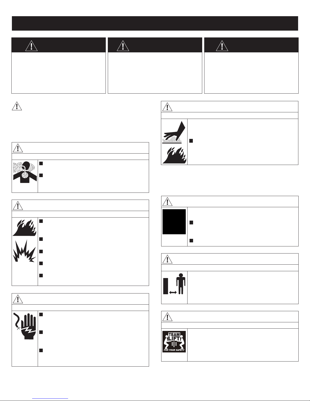
DANGER WARNING CAUTION
DANGER indicates a potenally
hazardous situaon which, if not
avoided, WILL result in death or
serious injury.
WARNING indicates a potenally
hazardous situaon which, if not
avoided, could result in death or
serious injury.
CAUTION indicates a potenally
hazardous situaon which, if not
avoided, may result in minor or
moderate personal injury, or
property damage.
To reduce the risk of serious injury or even death,
read the following safety precauons and operang
instrucons before operang.
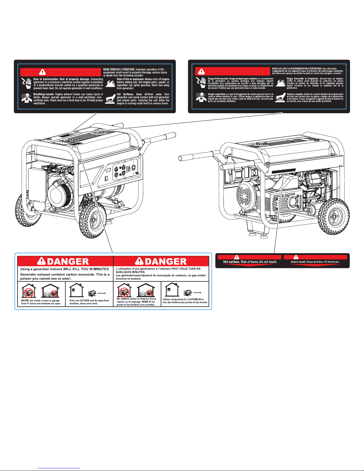
WARNING
DANGER
Using a generator indoors WILL KILL YOU IN MINUTES
Generator exhaust contains carbon monoxide. This
is a poison you cannot see or smell.
NEVER use inside a home or garage, even IF doors
and windows are open; only use OUTSIDE and far
away from windows, doors and vents.
DANGER
ELECTRICAL SHOCK
Never operate the generator in rain, in wet or
damp locaons, or with wet hands, a serve
electrical shock may occur causing serious injury.
Generator should not be operated or stored in wet
or damp condions or on highly conducve
locaons such as metal decking and steel work.
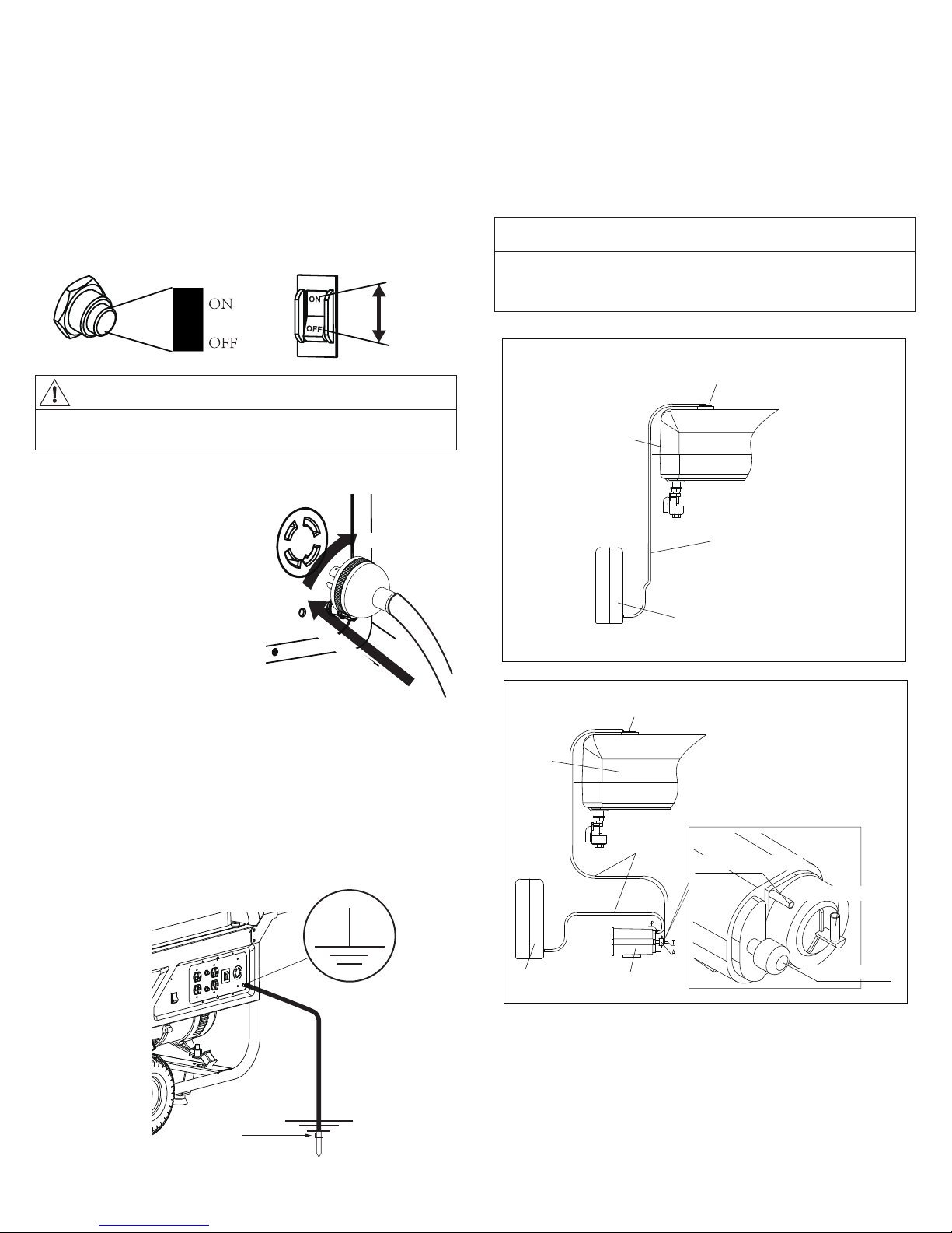
Always make sure the generator is properly
grounded before operang. Failure to do so may
result in serious injury.
DANGER
FUEL IS HIGHLY FLAMMABLE AND EXPLOSIVE
Always turn off the engine before adding fuel. Hot
engine parts, sparks or cigarees can ignite
gasoline. Store fuel away from generator.
Never refuel while smoking or in the vicinity of an
open flame.
Take care not to spill any fuel on the engine or
muffler when refueling.
Before transporng the generator in a vehicle,
drain all fuel to prevent leakage.
Store the generator in a well venlated area with
the fuel tank empty.
WARNING
ENGINE AND MUFFLER MAY BE HOT
Contact with muffler area can result in serious burns.
Exhaust heat/gases can ignite combusbles,
structures or damage fuel tank causing a fire.
DO NOT touch hot parts and AVOID hot exhaust
gases. Allow equipment to cool before touching.
U.S. Code of Federal Regulaon (CFR) Title 36 Parks, Forests, and Public Property require
equipment powered by an internal combuson engine to have a spark arrester, maintained in
effecve working order, complying to USDA Forest service standard 5100-1C or later revision.
In the State of California a spark arrester is required under secon 4442 of the California
Public resources code. Other states may have similar laws.
WARNING
Starter and other rotang parts can entangle hands,
hair, clothing, or accessories.
Do not wear loose clothing, jewelry, or anything
that may be caught in the starter or other
rotang parts.
Tie up long hair when operang the generator.
WARNING
KEEP CHILDREN AND PETS AWAY
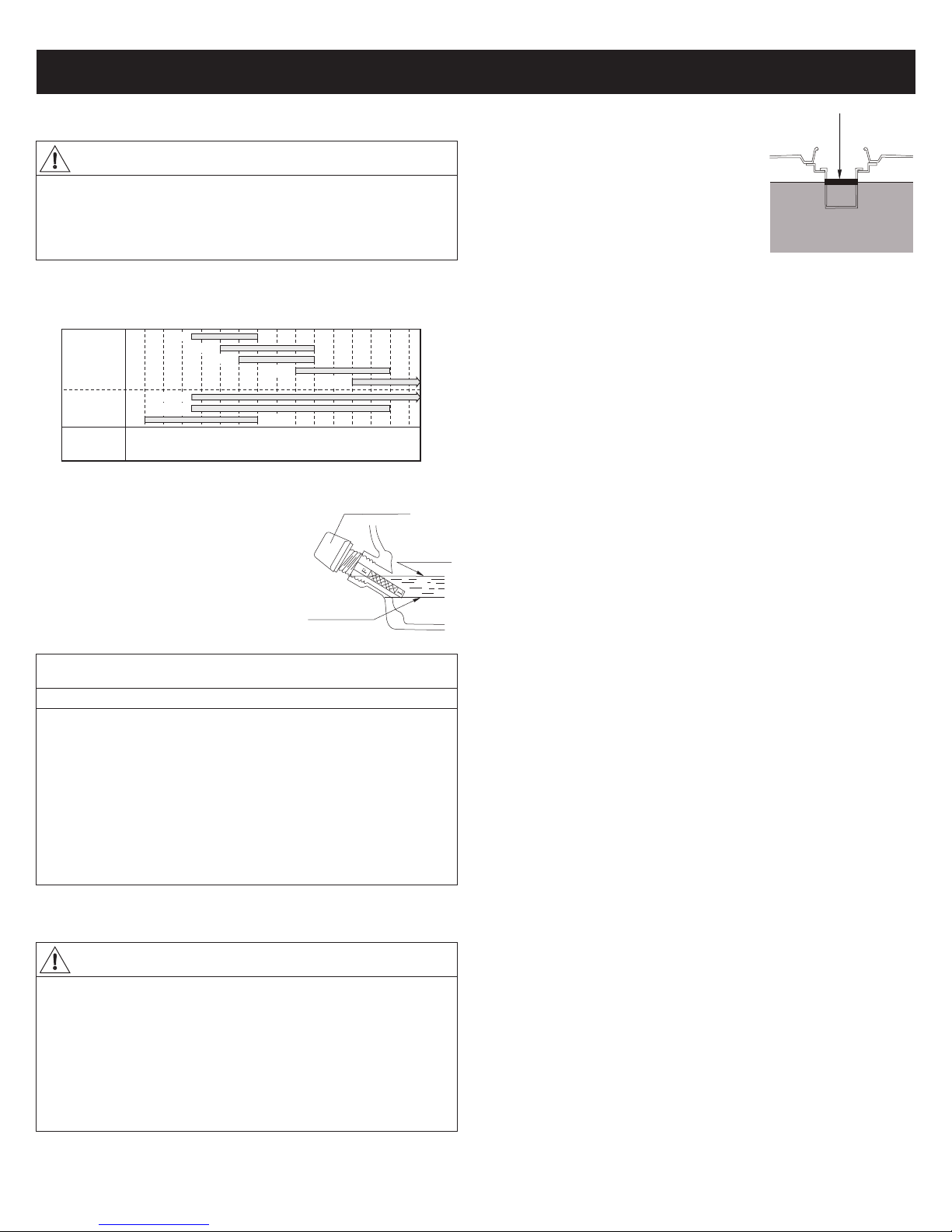
Keep bystanders, especially children and pets, at
least 50 feet (15m) from the generator. Do not let
children touch the generator. When not in use, the
generator should be stored in a dry, locked locaon,
out of reach of children.
15m
CAUTION
HEAVY LOAD
Use proper liing techniques when transporng the
generator from site to site. Improper liing
techniques may result in personal injury.
SAFETY INSTRUCTIONS
- 2 -

- 3 -
CAUTION
Improper treatment can damage the unit and shorten its life
To prevent surging that may possibly damage the equipment, do
not allow engine to run out of fuel when electrical loads are
applied.
Do not sck anything through venlang slots, even when the
generator is not operang. This can damage the generator or
cause personal injury.
The generator will do a beer and safer job if it is used at the rate
for which it was designed.
Do not connect the generator to another generator to use in
parallel. Doing so may result in damage to the internal
components.
Extension cords, power cords, and all electrical equipments must
be in good condion. Never operate electrical equipment with
damaged or defecve cords.
Load must be kept within rang stated on generator nameplate.
Overloading will damage the unit or shorten its life.
Engine must not be run at excessive speeds. Operang an
engine at excessive speeds increases the hazard of personal
injury. Do not tamper with parts which may increase or
decrease the governed speed.
CAUTION
The unit should never be operated under these condions
a. Uncontrolled change in engine speed.
b. Electrical output loss.
c. Overheang in connected equipment.
d. Sparking.
e. Damaged receptacles.
f. Engine misfire.
g. Excessive vibraon.
h. Flame or smoke.
i. Enclosed compartment.
j. Rain or inclement weather. Do not let the unit get wet when
operang.
NOTICE
Engine oil is hazardous to the environment
Be very careful when changing the oil to prevent spilling onto the
ground. Even if it is washed away, it will not mix with water and
will pollute the watershed—having a negave impact on the
plants and animals that it comes in contact with.
When disposing of engine oil:
1. While changing the engine oil, place a drip pan under the oil
plug to collect the waste.
2. Soak up any spills with sawdust, kiy lier, or sand. NEVER
dump down the drain or sewer.
3. Take the oil and filter to an oil recycling center.

- 4 -
WARNING AVERTISSEMENT
WARNING
AVERTISSEMENT

TOTAL WATTAGE, VOLTAGE AND INSTALLATION
- 5 -
In order to prevent overloading and possible damage to your
generator it is necessary to know the total waage of the connected
load. To determine which tools and/or appliances your generator
will run follow these steps:
1. Determine if you want to run one item or mulple items
simultaneously.
2. Check waage requirements for the items you will be running by
referring to the load’s nameplate or by calculang it (mulply amps
x volts = was).
3. Total the was for each item. If the nameplate only gives volts
and amps, mulply volts x amps = was. 1 KW = 1,000 was.
4. Motorized appliances or tools require more than their rated
waage for start up.
NOTE: Allow 2 1/2 to 4 mes the listed waage for starng
equipment powered by electric motors.
5. The generator’s rated was should match or exceed the total
number of was required for the equipment you want to run.
6. Always connect the heaviest load to the generator first, then add
other items one at a me.
TOTAL WATTAGE
VOLTAGE
INSTALLATION
WARNING
Operang voltage and frequency requirement of all electronic
equipment should be checked prior to plugging them into this
generator. Damage may result if the equipment is not designed to
operate within a +/- 10% voltage variaon, and +/- 3 Hz frequency
variaon from the generator name plate rangs. To avoid damage,
always have an addional load plugged into the generator if solid
state equipment (such as a television set) is used. A power line
condioner is recommended for some solid state applicaons.
A power line condioner should be used when running one or more
of the following solid state items:
Garage door openers, Kitchen appliances with digital displays,
Televisions, Stereos, Personal computers, Quartz clocks, Copy
machines, Telephone equipment, and other solid state equipment
may require a power line condioner.
WARNING
To avoid possible personal injury or equipment damage, a
registered electrician or an authorized service representave
should perform installaon and all services. Under no
circumstances should an unqualified person aempt to wire into a
ulity circuit.
To avoid back feeding into ulity systems, isolaon of the residence
electrical system is required.
Before temporary connecon of the generator to the residence
electrical system, turn off the main service/disconnect.
If your generator is to be used as a stand-by power source in case of
ulity power failure, it should be installed by a registered
electrician and in compliance with all applicable local electrical
codes.
Proper use requires that a double throw transfer switch be installed
by a licensed qualified electrician so that the building's electrical
circuits may be safely switched between ulity power and the
generator's output, thereby prevenng back feed into the power
ulity's electrical system.
WARNING
To avoid back feeding into ulity systems, isolaon of the
residence electrical system is required. Before temporary
connecon of a generator to the residence electrical system turn
off the main switch. Before making permanent connecons a
double throw transfer switch must be installed. To avoid
electrocuon or property damage, only a trained electrician
should connect generator to residence electrical system. California
law requires isolaon of the residence electrical system before
connecng a generator to residence electrical systems. Temporary
connecon not recommended due to back feeding.
Always follow local codes and regulaons that apply to the
installaon of any item that concerns this product.
Style Ampere Receptacle AC Plug Descripon
Up to 20A NEMA
5-20R
NEMA
5-20R
NEMA
L14-30R
NEMA
5-20P
NEMA
5-20P
NEMA
L14-30P
Duplex
GFCI Duplex
- Ground Fault
Circuit Interrupter
Twist lock
Up to 20A
Up to 30A

FEATURES AND CONTROLS
- 6 -
10a
1. Fuel Tank Cap
2. Fuel Tank
3. Fuel Gauge (oponal)
4. Fuel Tank Breathing Valve
5. Engine Choke Lever
6. Fuel Shut-off
7. Air Filter
8. Recoil Starter
9. Oil Gauge
10. Engine Shut-off
10a. Hour Meter
(Only for MBG5500/7000/
MBG7000X)
11. 120 V, 20 Ampere Duplex
Receptacle
or GFCI (oponal)
12. AC Protector
(MBG5500, MBG6500 Only)
13. Circuit Breaker
14. 120/240 V, 20 Ampere
Twist lock Receptacle
15. Ground Terminal
16. Oil Drain Plug
17. Muffler
18. Spark Arrester
19. Carbon Canister
Inspecon Window
FULL
EMPTY
Fuel Gauge (3)
(oponal)
120 V, 20 Ampere Duplex Receptacle (11)
20 amps of current may be drawn from each half of
the receptacle. However, total power drawn must
be kept within nameplate rangs. These receptacles
may be used along with the twist lock receptacle
provided the generator is not overloaded.
120V, 20 Ampere GFCI Duplex Receptacle (oponal)
If your generator comes with GFCI duplex
receptacle, aer starng the engine, check the GFCI
for proper funconing by the following test
Push TEST buon, The RESET buon will pop out. Power is now
off at the outlets protected by the GFCI, indicang that the device
is funconing properly.
If TRIP does not appear when tesng, do not use the generator.
Call a qualified electrician.
To restore power, push RESET buon.
WARNING
If the RESET buon pops out during operaon, stop the generator
immediately and call a qualified electrician for checking generator
and the appliances.
The duplex 120V receptacle is protected by a GFCI. GFCI shuts off
the output current from the duplex 120V receptacle when a
ground fault occurs in the generator or the appliance. Please note
that other receptacles are not protected by GFCI.
CAUTION
procedure:
GFCI Duplex Receptacle

- 7 -
This is a system to control gasoline evaporaon. Do not remove the
hose, breathing valve and carbon canister when there is fuel in the
fuel tank
NOTE
AC Protector and Circuit Breaker (12 and 13)
Your generator is protected by an AC protector (expect MBG3500)
and circuit breaker. If the generator is overloaded or an external
short circuit occurs, the AC protector or circuit breaker will trip. If
this occurs, disconnect all electrical loads and try to determine the
cause of the problem before aempng to use the generator again.
If overloading causes the AC protector and circuit breaker to trip,
reduce the load.
Ground Terminal (15)
Your generator needs to be properly connected to an appropriate
earth ground to help prevent electric shock. A ground terminal
connected to the frame of the generator has been provided for this
purpose.
Connecng a length of heavy gauge (12 AWG min.) copper wire
between the generator Ground Terminal and a copper rod driven
into the ground should provide a suitable ground connecon.
However, consult with a local electrician to insure that local codes
are being adhered to.
Fuel Tank Breathing Valve (4) & Carbon Canister (19)
Your generator may be equipped with breathing valve and carbon
canister required by Secon 213 of the Clean Air Act (42 U.S.C.
secon 7547), 40 CFR Part 90, 40 CFR Part 1054, 40 CFR Part 1045
or 40 CFR Part 1060 and California Health and Safety Code, Secon
39600, 39601and 43013.
120/240 V, 30 Ampere Twistlock Receptacle (14)
A maximum of 30 amps may be
drawn from the 120/240 volt
receptacle, provided it is the only
receptacle used. However, current
must be limited to the nameplate
rang. If the 120/240 volt
receptacle is used along with the
120 volt receptacle, the total load
drawn must not exceed the
nameplate rangs.
ON
OFF
WARNING
Connuous tripping of the AC protector or circuit breaker may
cause damage to generator or equipment.
2) TWIST
1) INSERT
Grounding Spike
Fuel Tank Breathing Valve
Carbon Canister
Air Filter
Hose
Fuel Tank
P: Purge(to air filter)
T: Tank(to fuel tank)
A: ATM(to air)
California
Fuel Tank Breathing Valve
Air Filter
Hose
Fuel Tank
49 States
Ground Terminal location

PORTABILITY KIT INSTALLATION
- 8 -
NUT, FLANGE M8
BRACKET, FOOT
RUBBER FOOT
BOLT, FLANGE M8×25
NUT, FLANGE M8
BOLT, FLANGE M8×16
AXIAL, WHEEL
PIN Ф3.2
GASKET Ф27xФ16.5
WHEEL, 10"
BOLT, FLANGE M8×55
HANDEL
CUSHION, HANDEL
NUT, FLANGE M8
GASKET, NYLON Φ8
Step 1
Step 3 Step 4
Step 2

BEFORE OPERATION
- 9 -
Use class SE oil or a higher grade according to the table below. SAE
10W-30 or 10W-40 is recommended for general, all temperature
use.
Check Engine Oil
CHECK AIR CLEANER TO MAKE SUR IT IS CLEAN
WARNING
DO NOT aempt to start this engine without filling the crank case
with the proper amount and type of oil. Your generator has been
shipped from the factory without oil in the crankcase. Operang
the unit without oil can damage the engine.
Single
Grade
Oil
Multiple
Grade
Oil
Temperature°
°
C
F
–30 –20 –10 0 10 20 30 40
–22 –4 14 32 50 68 86 104
10W 20W20# 30# 40#
10W-40
10W-30 5W-20
- Inspect the oil level by using the oil gauge
before starng the engine each me;
- Top up the oil level to the maximum level
mark and/or unl oil flows from the
opening;
- Ensure both Oil Gauges are secure.
Fill the tank with clean, fresh unleaded
automove gasoline
- Check fuel level.
- If fuel level is low, refill with unleaded
automove gasoline.
- Be sure to use the fuel filter screen on the
fuel filter neck.
If not, please refer to “HOW-TO” MAINTENANCE.
Check Loose and Missing Parts
Check the Generator to Make Sure It Is Correctly
Grounded
Before starng the generator, check for loose or missing parts and
for any damage which may have occurred during shipment.
OIL GAUGE
Regular Oil
Level
Lowest Oil Level
(Not Tightened)
NOTICE
Low oil sensor
The unit is equipped with a low oil sensor. If the oil level becomes
lower than required, the sensor will acvate a warning device or
stop the engine.
If generator shuts off and the oil level is within specificaons,
check to see if generator is sing at an angle that forces oil to shi.
Place on an even surface to correct this.
If engine fails to start, the oil level may not be sufficient to
deacvate low oil level switch. Make sure the sump is completely
full of oil.
Check Engine Fuel
WARNING
DO NOT refuel while smoking or near open flame or other such
potenal fire hazards. Otherwise a fire accident may occur.
- Do not refill tank while engine is running or hot.
- Close fuel cock before refueling with fuel.
- Be careful not to admit dust, dirt, water or other foreign objects
into fuel.
- Wipe off spilt fuel thoroughly before starng engine.
- Keep open flames away.
Fuel Level

OPERATING THE GENERATOR
- 10 -
Start the Generator
Stop the Generator
WARNING
To avoid accidently hurng people nearby when pulling the
starter handle, Please keep bystanders, especially children and
pets, away.
CAUTION
Do not allow the starter handle to snap back against the engine.
Return it gently to its starng posion to prevent damage to the
starter or the housing.
CAUTION
When applying a load, do not exceed the maximum waage
rang of the generator when using one or more receptacles. Also,
do not exceed the amperage rang of any one receptacle.
CAUTION
Do not apply heavy electrical load during break-in period (the first
two to three hours of operaons)
CAUTION
Move the engine stop switch to the “OFF” posion to stop engine
directly in an emergency situaon.
1. Disconnect all electrical
loads from the generator;
2. Set the circuit breaker to the
“OFF” posion;
3. Open the fuel shut off;
4. Set the engine stop switch to the
“ON” posion;
5. Set the choke lever to “Choke”
positon. Not necessary if the
engine is warm;
7. As the engine warms up,
readjust the choke lever to
“OPEN” poson;
CHOKE
6. MANUAL START
Pull the starter handle slowly unl
resistance is felt. This is the
“compression” point. Then, return the
handle to its original posion and pull
swily unl engine starts.
OPEN
1. Remove enre electrical load;
2. Let the engine run for two minutes without load;
3. Move the engine stop switch to the “OFF” posion or turn the key
to “OFF” posion;
4. Do not leave the generator unl it has completely stopped;
5. Close the fuel shut off valve if the engine is to be put in storage or
transported;
6. If a cover is used, do not install unl unit has cooled.
OFF
ON
ON
ELECTRIC START(oponal feature)
Turn the key to “START” Posion unl
the engine starts,then release the
key so it could return to “ON”
posion automacally;
START / DÉBUT
ON / MARCHE
OFF / ARRÊT
KEY
8. Apply load only aer generator is
running. Voltage is regulated via the
engine speed adjusted at the factory
for correct output. Readjusng will
void warranty.
9. Set all breakers to “ON” Posion;
ON

MAINTENANCE
- 11 -
1. Maintenance Schedule
CAUTION
To prevent accidental starng, always remove the spark plug or
cable from the spark plug before maintaining the generator or
engine.
ITEM REMARKS
DAILY
Before Operaon
INITIAL
25HR
EVERY
50HR
EVERY
100HR
SparkPlug
Checkcondion adjust gap and clean.Replace if
necessary
●
Engine Oil
Checkoil level ●
Replace ●●
Air Filter Clean,replace if necessary●
Fuel Filter Clean and adjust.Replace if necessary●
Fuel Hose
Checkfuel hose for crackor damage.Replace if
necessary
●
Exhaust
System
Checkfor leakage.Reghten or
replace gasket if necessary
●
Checkmuffler screen.Clean/replace if
necessary
●
Carburetor checkchoke operaon ●
Cooling
System
Checkfan damage●
Starng
System
Checkrecoil starter operaon ●
Fings
Fasteners
Checkall fings and
fasteners correct if necessary
●

- 12 -
2. “How-To” Maintenance
Engine Oil Change
Clean Spark Plug
Clean Carbon Brush
1. Drain oil by removing the drain
plug and the oil gauge while
engine is warm.
2. Reinstall the drain plug and fill
the engine with oil unl it
reaches the upper level on the oil
filler cap.
3. Clean the oil on the panel.
Dispose of used oil in local
authority disposal site.
1. If the plug is contaminated
with carbon, remove it using a
plug cleaner and wire brush.
2. Adjust the electrode gap to 0.7
to 0.8 mm.
The brush is the area which touches
the slip ring, and its surface must be
kept smooth.
If the brush becomes excessively
worn, its contact pressure with
the slip ring changes and causes a
roughened surface on the slip
ring, resulng in irregular
generator performance.
Check the brush every 300 hours
or if generator performance is
irregular.
If the brush is 0.2 in (5mm) long
or less, replace it with a new one.
Oil Gauge
Oil Drain Plug
WARNING
Engine oil may be hot.
Engine GT241/400/600 GT1000/GT1300
Manufacturer NGK Bosch
NGK Denso Champion Bosch
Product No. BP6RSH E6RTC BPR5ES W16EPR RN11YC WR8DC+
Clean Air Filter
1. Unscrew the air filter cover;
2. Remove filter element and wash
well in solvent;
3. Pour a small amount of oil onto the
filter element and gently squeeze out
any excess oil;
4. Replace the filter element and air
filter cover;
5. Be sure the filter cover seals
properly all around.
Element Holder
Element
5 mm
10~11mm
Length when new
Flange bolts
Brush holder
Bracket cover
Flange bolts
Slip ring
Brush
STORAGE
OIL
OPEN
Drain screw
Besides draining fuel from fuel tank, the
following procedures should be followed
prior to storage of your generator for
periods of 3 months or longer.
1. Turn fuel shut off to “OPEN” posion.
2. Loosen the drain screw on the side of
the carburetor float chamber, and drain
the fuel completely.
NOTE
1) There are two screws on carburetor.
The vercal one is the screw to hold the
carburetor float chamber; the other one
on the side of the carburetor float
chamber is the drain screw.
2) Tighten the drain screw very carefully
to avoid damaging the fuel cup.
3. Remove the spark plug, pour 2 to 3 cc of
engine oil into the cylinder, and turn the
crank sha several mes.
4. Replace the spark plug and pull starter
handle unl resistance is felt.
5. Store the generator in a well venlated,
low humidity area.
Let engine cool at least 2 minutes before removing
fuel cap. Loosen cap slowly to relieve pressure in
tank.

- 13 -
NOTE
TROUBLE SHOOTING
Condion Cause Correcve Acon
Engine won't
start
Low engine
output
Engine runs
erracally
Insufficient
compression
Loose spark plug Tighten plug properly
Loose cylinder head bolt Tighten bolt properly
Damaged gasket Replace gasket
Sufficient
compression
No fuel
supplied to
combuson
chamber
1. Insufficient pulling speed for
starng rope
Pull rope sharply
2. Foreign maer in fuel tank Clean tank
3. Clogged fuel line Clean fuel line
4. No fuel in tank Refill tank
5. Fuel switch not open Open valve
Combuson
chamber
supplied with
fuel
1. Spark plug dirty with carbon
or wet with fuel
Remove carbon or wipe out spark
plug
2. Damaged spark plug Replace spark plug
3. Faulty Magneto
Consult the Service Center
4. Improper adjustment of
carburetor
Improper grade of fuel used
Make sure the proper grade of fuel
has been used
Overloading Make sure you haven’t plugged in too
many devices. Check fan
Overheang
Lower oil level Add sufficient oil as specified.
Engine ON, yet
no AC output
Tripped circuit breaker Reset
Poor connecon or faulty lead Check and repair
Broken receptacle
Contact the Service Center
Faulty circuit breaker
Generator problem
If your generator experiences a low engine oil condion, the engine will automacally shut off. Please check the oil first if you cannot start
the generator.

- 14 -
SPECIFICATION
(※) rated 6000W for Canadian model in accordance with CSA regulations.
MODEL NO. MBG1200 MBG3500 MBG5500
Alternator
Type / Voltage regulaon: Brush/AVR Brush/AVR Brush/AVR
Frequency: 60 Hz 60 Hz 60 Hz
Voltage: 120 V 120/240 V 120/240 V
Rated Was: 1000 W 2800 W 5000 W
Starng Was: 1200 W 3500 W 5500 W
Engine
Brand / Model: MITSUBISHI GT241 MITSUBISHI GT600 MITSUBISHI GT1000
Type: OHV, 4 Stroke, Air cooled OHV, 4 Stroke, Air cooled OHV, 4 Stroke, Air cooled
Displacement: 79.6 cc 181 cc 296 cc
Fuel Tank Size: 1.85 Gallon / Unleaded Gasoline 4 Gallon / Unleaded Gasoline 7 Gallon / Unleaded Gasoline
Run Time @ 75% load 10 Hours / Tank 10.3 Hours / Tank 11.4 Hours / Tank
Lubricang oil: 0.1 Gallon / Engine oil SD or Higher 0.16 Gallon / Engine oil SD or Higher 0.32 Gallon / Engine oil SD or Higher
Starng System: Manual Start Manual Start Manual Start
Oil Alert: Equipped Equipped Equipped
Fuel Gauge: Optional Optional Optional
Control Panel
Outlets: (2)120V,20A outlets
(4)120V,20A outlets,
(1)120/240V,30A Twistlock Outlet
(4)120V,20A outlets,
(1)120/240V,30A Twistlock Outlet
Hour Meter - - Optional
Circuit Breaker: Equipped Equipped Equipped
Overview
Weight: 60.6 Lbs. (27.5 kilograms) 99 Lbs. (45 kilograms) 174 Lbs. (79 kilograms)
Dimensions: 18.5''L×14.9'' W×15.4'' H 22.6'' L×17.3'' W×18.9'' H 28.5'' L×20'' W×22.5'' H
MODEL NO. MBG6500 MBG7000 MBG6500X MBG7000X MBG2902
Alternator
Type / Voltage regulaon:
Brush/AVR Brush/AVR Brushless/Condenser
Frequency: 60 Hz 60 Hz 60 Hz
Voltage: 120/240 V 120/240 V 120 V
Rated Was:
6000 W (
※
) 6500 W 6500 W6000 W (
※
) 2800 W
Starng Was: 7000 W 7000 W 3500 W
Engine
Brand / Model: MITSUBISHI GT1300 MITSUBISHI GT1300 MITSUBISHI GT600
Type:
OHV, 4 Stroke, Air cooled OHV, 4 Stroke, Air cooled OHV, 4 Stroke, Air cooled
Displacement: 391 cc 391 cc 181 cc
Fuel Tank Size: 7 Gallon / Unleaded Gasoline 7 Gallon / Unleaded Gasoline 2.6 Gallon / Unleaded Gasoline
Run Time @ 75% load 8.4 Hours / Tank 8.4 Hours / Tank 6.7 Hours / Tank
Lubricang oil: 0.32 Gallon / Engine oil SD or Higher 0.32 Gallon / Engine oil SD or Higher 0.16 Gallon / Engine oil SD or Higher
Starng System: Manual Start Manual / Electric Start Manual Start
Oil Alert: Equipped Equipped Equipped
Fuel Gauge: Optional Optional Optional
Control Panel
Outlets:
(4)120V,20A outlets,
(1)120/240V,30A Twistlock Outlet
(4)120V,20A outlets,
(1)120/240V,30A Twistlock Outlet
(4)120V,20A outlets
Hour Meter
Optional Optional -
Circuit Breaker: Equipped Equipped Equipped
Overview
Weight: 187 Lbs. (85 kilograms) 187 Lbs. (85 kilograms) 106 Lbs. (48 kilograms)
Dimensions: 28.5'' L×20'' W×22.5'' H 28.5'' L×20'' W×22.5'' H 24'' L×17.3'' W×20'' H

LIMITED WARRANTY
This Mitsubishi engine product carries a guarantee of 24 months. If
your product develops a fault within this period, DO NOT return to
store, you should, in the first instance contact our customer
service.
We welcome warranty repairs and apologize to you for being
inconvenienced. Any Authorized Service Dealer may perform
warranty repairs. Most warranty repairs are handled rounely, but
somemes requests for warranty service may not be appropriate.
To avoid misunderstanding which might occur between the
customer and the dealer, listed below are some of the causes of
engine failure that the warranty does not cover.
Normal wear: Engines, like all mechanical parts, need periodic
parts service and replacement to perform well. Your warranty will
not cover repairs when wear has occurred because of misuse, lack
of roune maintenance, shipping, handling, has exhausted the life
of a part or an engine. Warranty would not apply if engine damage
occurred because of misuse, lack of roune maintenance, shipping,
handling, warehousing or improper installaon. Similarly, warranty
is void if the serial number of the engine has been removed or the
engine has been altered or modified.
Improper maintenance: The life of an engine depends upon the
condions under which it operates, and the care it receives. Oen
used in dusty or dirty condions, which can cause what appears to
be premature wear. Such wear, when caused by dirt, dust, spark
plug cleaning grit, or other abrasive material that has entered the
engine because of improper maintenance, is not covered by
warranty.
This warranty covers engine related defecve material and/or
workmanship only, nor does the warranty extend to repairs
required because of:
1. Problems caused by parts that are not original parts.
2. Leaking carburetors, clogged fuel pipes, scking valves, or other
damage, caused by using contaminated or stale fuel.
3. Parts which are scored or broken because an engine was
operated with insufficient or contaminated lubricang oil, or an
incorrect grade of lubricang oil (check and refill when necessary,
and change at recommended intervals). OIL GARD may not shut
down running engine. Engine damage may occur if oil level is not
properly maintained.
4. Damage or wear to parts caused by dirt, which entered the
engine because of improper air cleaner maintenance, re-assembly,
or use of a non-original air cleaner element or cartridge. At
recommended intervals, clean and/or replace the filter as stated in
the Operator’s Manual.
5. Parts damaged by over-speeding, or overheang caused by
grass, debris, or dirt, which plugs or clogs the cooling fins, or
flywheel area, or damage caused by operang the engine in a
confined area without sufficient venlaon. Clean engine debris at
recommended intervals as stated in the Operator’s Manual.
6. Engine or equipment parts broken by excessive vibraon caused
by a loose engine mounng, or unbalanced impellers, improper
aachment of equipment to engine, over-speeding or other abuse
in operaon.
7. Roune tune-up or adjustment of the engine.
8. Engine or engine component failure, i.e., combuson chamber,
valves, valve seats, valve guides, or burned starter, caused by the
use of gasoline formulated with ethanol greater than 10%.
Service Informaon
contact
1-888-666-0292
info@brillianndustry.com
to find out closest repair center,
to obtain warranty service informaon
or to order replacement parts or accessories.
HOW TO ORDER REPLACEMENT PARTS
To order replacement parts, please give the following us informaon:
1. Model No. and Serial No. and all specificaons shown on the Model No./Serial No. plate.
www.brilliantindustry.com
Head Office: 159 N. Central Ave. Valley Stream, NY 11580
MBG12AAA-07203
Brilliant Group Industry Inc.
This manual suits for next models
7
Table of contents
Other Mitsubishi Portable Generator manuals
Popular Portable Generator manuals by other brands

Kübler
Kübler CODIX 533 manual

Rohde & Schwarz
Rohde & Schwarz HMF2525 user manual

Briggs & Stratton
Briggs & Stratton PRO8000 01934 owner's manual

Leroy-Somer
Leroy-Somer LSA 50 AREP Installation and Maintenance

DUROMAX
DUROMAX DuroStar DS4850EH user manual

LawnMaster
LawnMaster LGBQH6200 Safety and operating manual