3 Installation
Installation
06
3.1 Quick Start Guide
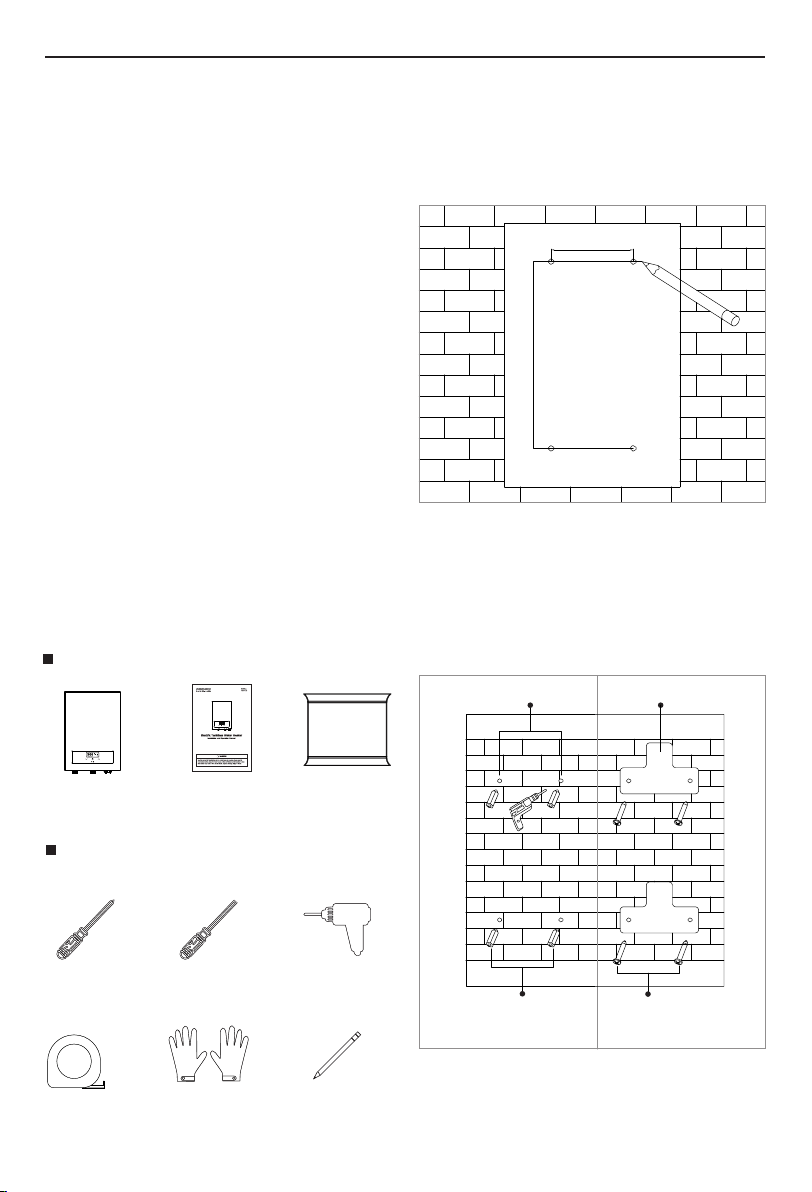
Mounting
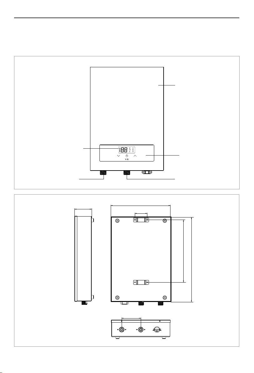
2. Plumbing connections are 3/4"NPT,and both the
inlet and outlet can be found at the bottom of
the unit. When installing your water connections
make sure to use 3/4"NPT fittings.
4. NEVER USE PVC ON HOT WATER OUTLET. Use
instead CPVC or other high temperature rated
materials.
1. For the best service and lifespan of the hot water
unit, it is advised that a descaler device should
be installed inline to the supply line (cold) to
avoid any potential damage due to scale build-
up.
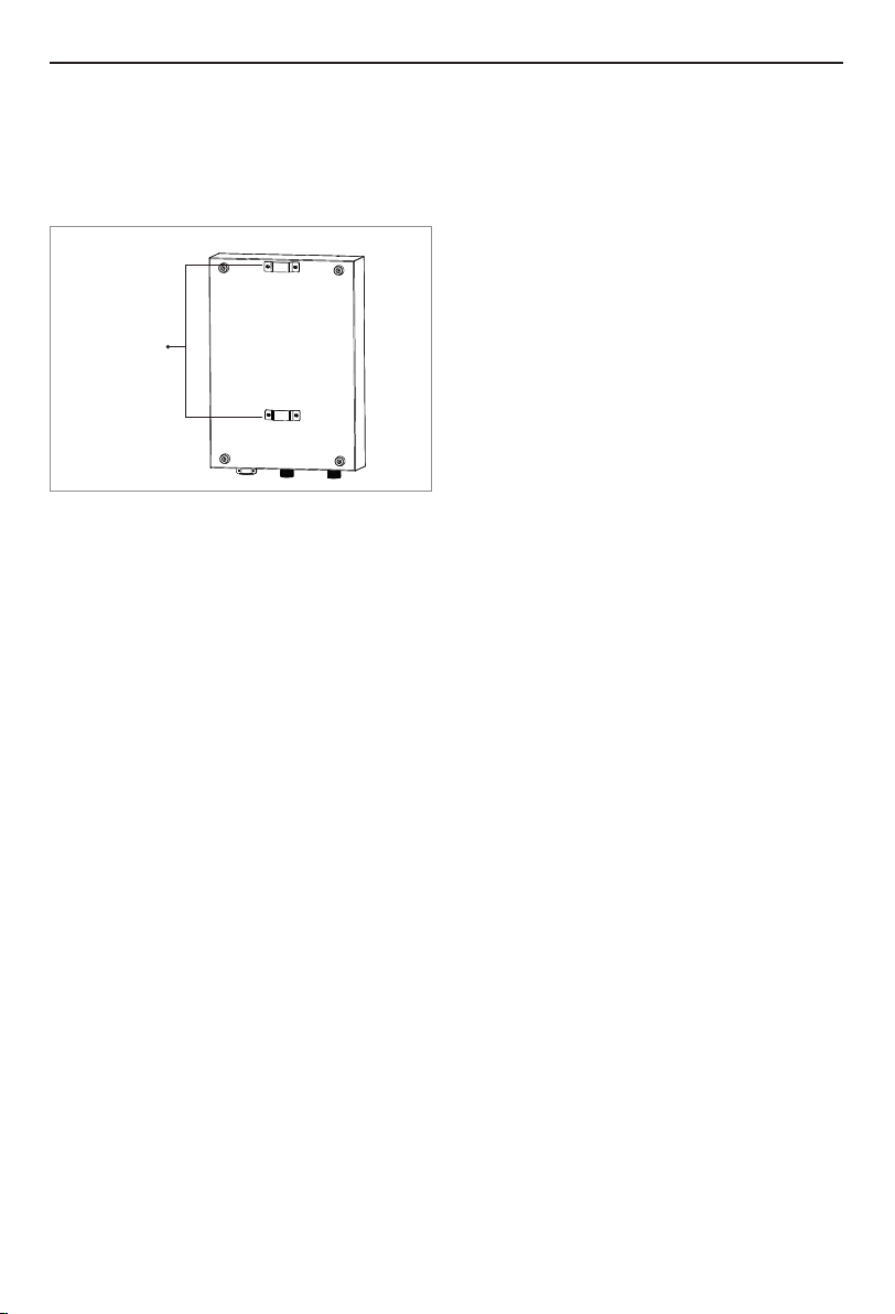
The unit should be installed vertically on a flat
surface that is larger than the unit itself. Drill 4
holes into the wall for mounting screws, in
accordance with the installation template. Make
sure the unit is securely mounted by those 4 wall
anchor and screws provided. Keep the unit away
from any slashing or leaking water, also strong
magnetic field.
Water Connections
3. Please use the provided gaskets to prevent leaks.
5. Run water through the heater for a few minutes
to purge all air from the system. Shut off flow at
faucet to pressurize system. At this point check
for and fix any leaks. If no leaks are present
move to next step.
Power wires with Grounding gets into the terminal
blocks located right bottom of the unit. 2 set of
8AWG/2 wires with Grounding wire should run from
a 2X40A double pole breaker on the home main
breaker panel, to the water heater unit terminal
blocks. Securely tightened to get 240V supply.
Water Connections
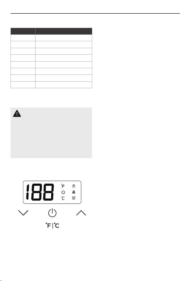
Operation
After power is switched on a beep can be heard
and display lights up. First open the water faucet
to purge all the air inside the unit, and then press
power button on the unit to turn on, Set Temp, and
the temperature can be set between 86-131°F. Set
desired temp with the UP and DOWN arrows. Test
water before use to avoid scalds.
CAUTION
This unit requires a 2X40A double pole
breaker. For more information please
consult a certified electrician in your area.
3.2 Before Installation Process
4. Make sure that the water heater and hot water
outlet pipe are out of reach of children so they
are unable to tamper with the temperature
controls or injure themselves by touching the hot
water outlet pipe. The outlet water pipe can get
very hot.
Guideline You Should Know
1. This product is designed to be installed indoors
only. You may install your unit in an outdoor
location so long as it is mounted in a suitable
enclosure that protects it from rain, splashed
water, freezing temperature, direct sunlight,
debris and insects.
2. DO NOT install this product in a location where it
may be subjected to freezing temperatures. If the
water inside your tankless water heater freezes, it
can cause severe and permanent damage that is
not covered under your warranty.
3. DO NOT locate the water heater in a location that
is difficult to access.
7. DO NOT install above electrical boxes or
junctions.
6. DO NOT install under water pipes or air
conditioning lines that might leak or condense
moisture that could then drip onto the heater.
5. Avoid installing your tankless water heater in a
location prone to excessive humidity, moisture or
dust, or in an area where it may be splashed
with water or other liquids.
CAUTION
The water heater should not be located in
an area where leakage will result in
damage to the area adjacent to it or to
lower floors of the structure. Where such
areas cannot be avoided, it is
recommended that a suitable catch pan,
adequately drained, be installed under the
water heater.


 Operation and maintenance instructions")