Mizuho osi 5803 User manual

MIZUHOSI 2009 1NW0498 Rev E
ADVANCED CONTROL BASE
FOR THE
MODULAR TABLE SYSTEM
OWNER’S MANUAL
Model 5803
This manual is written in five
languages in the following order:
(en) English
(es) Spanish
(fr) French
(de) German
(it) Italian
MIZUHO OSI
30031 AHERN AVENUE UNION CITY, CA 94587
Bus: 510-429-1500 Toll Free: 800-777-4674 Fax: 510-429-8500
WWW.MIZUHOSI.COM ·NEWHIPNEWS.COM · NEWSPINENEWS.COM

MIZUHOSI 2009 NW0498 Rev E
2
IMPORTANT NOTICES
CAUTION: To ensure safe operation of the equipment, please READ THESE
INSTRUCTIONS COMPLETELY and keep this manual readily available for future
reference.
Carefully observe and comply with all warnings, cautions and instructions placed on the
equipment or described in this manual.
In this manual, the WARNING symbol is intended to alert the user to the presence
of important operation, maintenance, or safety instructions.
PROTECTION AGAINST ELECTRICAL SHOCK HAZARD:
This symbol indicates this equipment is an applied part, TYPE B in
accordance with IEC 60601-1 and is generally suitable for applications involving
external or internal contact with the patient, excluding the heart. The patient
circuit is connected to protective earth and this equipment should be connected
only to outlets with a protective earth ground.
This symbol indicates the external stud that is at the same potential as the
equipment chassis. If the AC power cable is not connected to an outlet with a
protective earth ground, this external stud should be connected to a protective
earth ground.
WARNING:
Proper preoperative and intraoperative procedures must be followed to prevent
venous stasis and pooling, pressure sore development, neuropathy, improper
electro-surgical tissue grounding, hypotension and hypothermia.
WARNING:
It is important to note that a Jackson Spinal Surgery or Imaging Table Top used
on the model 5803 Advanced Control Base must have gimbals. Earlier versions
of these table tops do not have gimbals. Use of table tops without gimbals on the
5803 Advanced Control Base can result in damage to the table and the base.
WARNING:
Prior to attempting to use the Modular Table Base, one should carefully review
this owners manual and keep a copy on file for further reference. It is
recommended that one also view the appropriate sections of the Modular Table
System instructional video provided with the table top.
This device is to be used by trained personnel only.

MIZUHOSI 2009 NW0498 Rev E
3
TABLE OF CONTENTS
1.0 INTRODUCTION..................................................................................................................................................5
1.1 General Description.........................................................................................................................................5
1.2 Specifications....................................................................................................................................................5
1.3 Shipping.............................................................................................................................................................5
1.4 Storage ..............................................................................................................................................................6
1.5 Acceptance & Transfer....................................................................................................................................6
1.6 Inspection and Transfer...................................................................................................................................6
2.0 GLOSSARY of TERMS......................................................................................................................................7
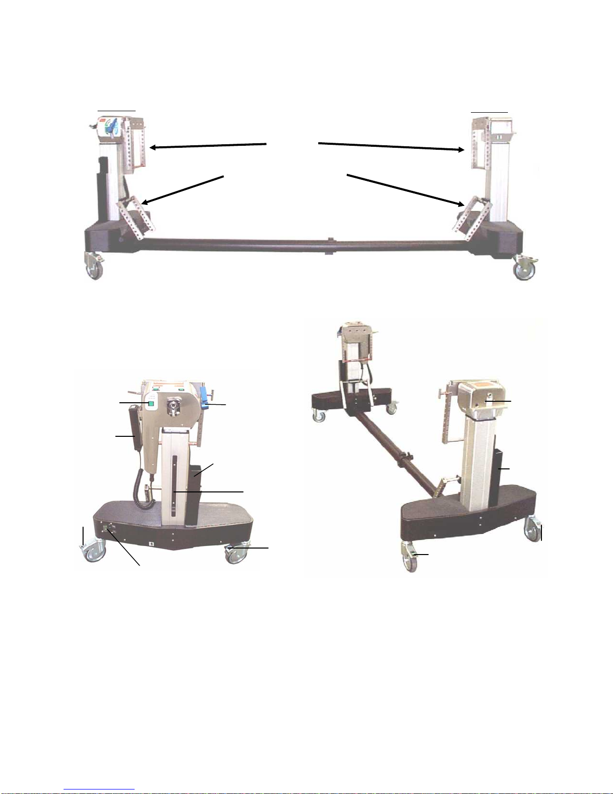
3.0 CONTROLS IDENTIFICATION.........................................................................................................................8
3.1 Base Orientation...............................................................................................................................................9
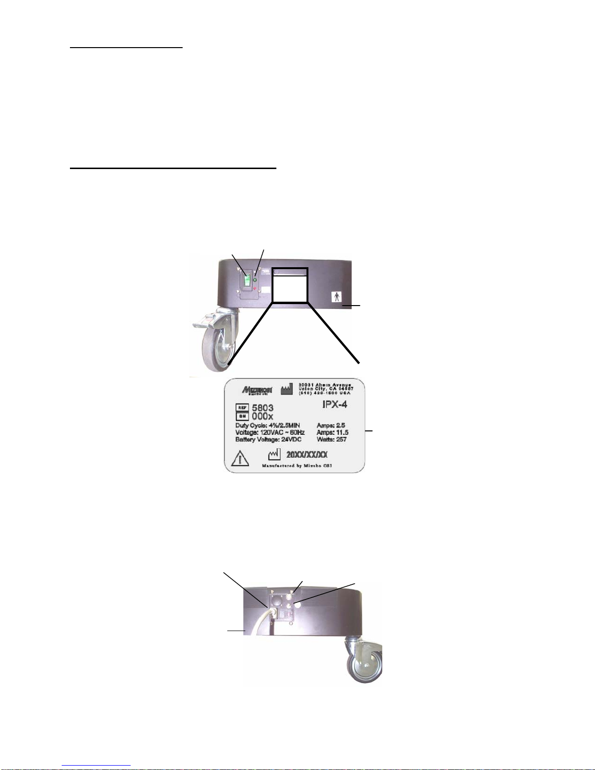
3.2 Model Number and Serial Number................................................................................................................9
4.0 BASIC OPERATION.........................................................................................................................................10
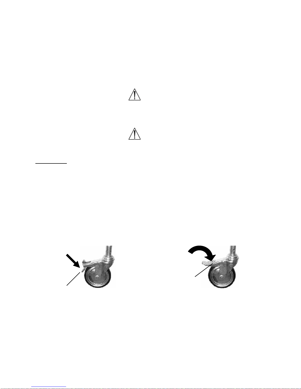
4.1 Casters.............................................................................................................................................................10
4.2 Hand Pendant.................................................................................................................................................11
4.3 5803 Advanced Base Controls.....................................................................................................................13
4.3.1 Rotation Safety Lock ..................................................................................................................................13
4.3.2 180° Rotation Lock Indicator.....................................................................................................................14
4.3.3 Tilt Drive Status Indicator...........................................................................................................................14
4.4 Synchronizing The Lateral Tilt Function......................................................................................................15
4.5 Tabletop Coupling Procedure.......................................................................................................................17
4.6 Patient Transfer..............................................................................................................................................19
4.7 Table Top Coupling Procedure With Top In Place....................................................................................19
4.8 Patient Rotation..............................................................................................................................................20
4.9 Rotation Lock System....................................................................................................................................20
4.10 Rotation Procedure......................................................................................................................................20
4.11 Retracting The Base For Storage..............................................................................................................21
4.12 Table Top on the Base................................................................................................................................22
5.0 PRE-OPERATIONAL FUNCTION CHECK...................................................................................................23
6.0 CLEANING and MAINTENANCE...................................................................................................................24
6.1 Cleaning and Disinfecting.............................................................................................................................24
6.2 Lubrication.......................................................................................................................................................24
6.3 Preventative Maintenance ............................................................................................................................25
7.0 THE ELECTRICAL SYSTEM...........................................................................................................................26
7.1 Power Cord.....................................................................................................................................................26
7.2 ON/OFF Power/Circuit-Breaker Switch.......................................................................................................26
7.3 Power ON / Fault / Battery Status Lights....................................................................................................26
7.4 Battery Recharging........................................................................................................................................26
8.0 TROUBLESHOOTING......................................................................................................................................27
8.1 Electrical System............................................................................................................................................27
8.2 Functional Guide............................................................................................................................................28
9.0 REMOVAL and REPLACEMENT of COMPONENTS.................................................................................30
9.1 Head end Cover .............................................................................................................................................30
9.2 Foot End Cover...............................................................................................................................................31
9.3 Hand Pendant Module...................................................................................................................................31
9.4 Batteries...........................................................................................................................................................32
9.5 Power Supply Replacement.........................................................................................................................34
9.6 Controller Circuit Board Replacement.........................................................................................................34
9.7 On-Off Power Switch / Circuit Breaker Replacement...............................................................................35
9.8 Head End Assembly ......................................................................................................................................35
9.9 Head End Tilt Motor.......................................................................................................................................35
9.10 Foot End Rotation Safety Lock Motor.......................................................................................................35
9.11 Head End or Foot End Column..................................................................................................................36
9.12 Retractable Center Beam...........................................................................................................................36
9.13 Casters ..........................................................................................................................................................36

MIZUHOSI 2009 NW0498 Rev E
4
10.0 ADJUSTMENT of COMPONENTS...............................................................................................................37
HEAD END ............................................................................................................................................................37
10.1 Tilt Actuator Rod End Position...................................................................................................................37
10.2 180° Rotation Lock Sensor.........................................................................................................................37
10.3 Home & Tilt Left/Right Sensors..................................................................................................................38
10.4 Head end Slider Adjustment Procedure...................................................................................................39
10.5 Rotation Safety Lock....................................................................................................................................40
10.6 Rotation Safety Lock (Brake) “ON” Sensor Setting.................................................................................41
11.0 Mizuho OSI TECHNICAL SERVICE............................................................................................................42
11.1 Contact for Parts and Service....................................................................................................................42
11.2 Instant Support Value Package .................................................................................................................42
11.3 To order Replacement Parts (RP).............................................................................................................42
11.4 To return damaged parts (RGA)................................................................................................................42
11.5 To send a part for repair (RA)....................................................................................................................43
11.6 EC Authorized Representative...................................................................................................................43
11.7 Replacement / Spare Parts List.................................................................................................................44
11.8 Replacement Parts......................................................................................................................................45
11.9 INTERCONNECT DIAGRAM....................................................................................................................46

MIZUHOSI 2009 NW0498 Rev E
5
1.0 INTRODUCTION
1.1 General Description
This manual describes the use, maintenance, and repair of the Modular Table System
(MTS) 5803 Advanced Control I-Base, DC (5803 Base). It is the primary component of
the system designed to support patients for a variety of surgical procedures. The 5803
Base is designed to hold a table top that will provide a patient support that is free of any
obstructions that might compete for space with a fluoroscopic C-Arm. There are five
procedure-specific table tops: Jackson Spinal, Radiolucent Imaging, Orthopedic
Trauma, Endourology and Maximum Access Lateral Top available for use on the MTS
Base.
1.2 Specifications
Maximum Patient Weight: Table top specific but not to exceed 500 lbs
Height Range of Base 34 - 48 inches (83.36 – 121 centimeters)
Trendelenburg Range 103
Reverse Trendelenburg 10° ±3°
Range
Powered Lateral Roll 253
Power Input (configurable)
o100 VAC at 50/60 Hz
o120 VAC at 60 Hz
o230 VAC at 50 Hz
ointernal battery power
Compatible Tabletops All MTS tops equipped with gimbals.
Maximum Length 102 inches (259 cm)
Retracted Length 64 inches (162 cm)
Width 32 inches (81 cm)
Maximum tilt torque 55 ft-lb
Maximum brake torque 93 ft-lb
Duty Cycle 4% or 2.5 minutes continuously per hour
1.3 Shipping
The 5803 Base must be shipped in a manner that prevents damage to its structural
elements, caster wheels, electronics, and operating controls. Contact with solid objects
in the environment must be prevented during shipment and storage, except at the four
casters. Banding for lateral constraint is to be limited to the base structure. Additionally,
banding of the head end assembly to prevent movement of the trolley is necessary. It is
also necessary to fully crate the 5803 Base to assure that no impact with foreign solid
objects will be made during transit. The 5803 Base is to be shipped in an environment
within the following limits:
Ambient temperature -4°F to 122°F (-20° C to +50° C)
Relative humidity from 10% to 100%, including condensation
Atmospheric pressure from 50 to 110 kPa.

MIZUHOSI 2009 NW0498 Rev E
6
1.4 Storage
When not in use, store in a clean, dry environment with temperature between 32°F and
120°F (0° C to 49°C).
It is recommended that the 5803 Base be stowed with the power cord plugged into a
proper AC receptacle with the on/off power-switch “on” to assure batteries are fully
charged and ready for service.
If recharge is required, charge a minimum of 3 hours. A full charge should be
available after 18 hours.
1.5 Acceptance & Transfer
Upon receipt of your table, remove the table from the shipping crate following the
unpacking instructions. Visually inspect all surfaces for freight damage. Check each
caster for proper rolling operation.
NOTE: Any freight damage must be reported to the freight carrier immediately upon
delivery. It is the responsibility of the recipient to make freight damage claims.
1. Read the model/serial number identification label found at the head end of the base
(see figure 4) to confirm the serial number and the input power requirements.
2. Perform pre-op function check; see section 5.0.
1.6 Inspection and Transfer
Before use, inspect the device for possible damage, excessive wear or non-functioning
parts. Carefully inspect all critical, inaccessible areas, joints, electrical cords and all
movable parts for possible damage or non-function.
Damaged or defective products should not be used or processed. Contact your local
MIZUHO OSI sales representative for repair or replacement.

MIZUHOSI 2009 NW0498 Rev E
7
2.0 GLOSSARY of TERMS
This glossary of terms and technical procedures assume the patient is oriented with
their head at the head end of table and their feet at the foot end of table. The hand
pendant functions are oriented for this position only.
Head end of base, indicates the end of the table where the power cord, "On-Off" switch,
and Control Panel are located.
Foot end of base, indicates the opposite end of the table.
Column, refers to one of two main column structures that support the tabletop.
Left side of the base, refers to the base as you stand at the head end of table.
Right side of the base, refers to the table as you stand at the front of column.
Raise the column, refers to raising the height of the column. This also corresponds to
Height Up.
Lower the column, refers to lowering the height of the column. This also corresponds to
Height Down.
Left lateral roll (tilt), refers to tilting the table top to the left when standing at the head
end of the base facing the foot end.
Right lateral roll (tilt), refers to tilting the table top to the right when standing at the head
end of the base facing the foot end.
Trendelenburg, refers to lowering the head end below the foot end.
Reverse trendelenburg, refers to lowering the foot end below the head end.
Hospital Grade, outlet refers to a 120VAC outlet properly wired with earth ground:
Neutral to Common = 120VAC; Neutral to Ground = 120VAC; Common to Ground less
than zero point five 0.5 VAC.

MIZUHOSI 2009 NW0498 Rev E
8
3.0 CONTROLS IDENTIFICATION
The major components of the 5803 Advanced Control Base are identified in the
following figures.
Figure 1: 5803 Advanced Control Base - Side View
H-Frame in Storage Bracket
H-Frame
Locking Caster Steer Caster
Head end Foot End
Center Bea
m
Retracting Lock Knob
Figure 2: 5803 Advanced Control Base - Head End View
Hand Pendant
Power Cord
Storage Wrap
Tilt Drive
Status Switch
Locking
Caster
On/Off Switch – Identification Label
Locking
Caster
180° Rotation
Lock
Quiver
T-Pin Storage
Figure 3: 5803 Advanced Control Base - Foot End View
Locking Caster
Steer Caster
Quiver
T-Pin Storage
Traction Arc
Interlocking
Switch

MIZUHOSI 2009 NW0498 Rev E
9
3.1 Base Orientation
The control end of the base is considered the head end, and the opposite end is the foot
end. The right side of the base is the side to the operator’s right when standing at the
head end looking toward the foot end. The general nomenclature and orientation of the
base is shown in figure 1, 2 and 3. Refer to the appropriate owners manual supplied
with each table top for table top component Identification and more detailed information
about the use of each table top.
3.2 Model Number and Serial Number
The model number and serial number are printed on the Identification label located at
the head end base. This label is located to the right of the on/off switch as shown
below.
Figure 4: Head End; Base Outside
Figure 5: Head End; Base Beam Side
Head end
Base
Beam Side
Power Cord
Plug In External Ground
Stud
Reset Button
Circuit Breaker
On/Off
Switch
Model/Serial
Number
Identification
Label
Head end
Base
Out Side
“Battery Status”
“Fault”, & Power lights

MIZUHOSI 2009 NW0498 Rev E
10
4.0 BASIC OPERATION
The 5803 Advanced Control Base uses an external AC power source or internal,
rechargeable, battery power for operation. It uses AC power when plugged into a proper
AC receptacle and the on/off power-switch is in the “on” position. When not plugged in,
or AC power is lost, the 5803 Base will automatically switch over to internal battery
power. The batteries are automatically recharged whenever the 5803 Base is plugged
into an AC power source and the on/off power-switch is in the “on” position. Located
next to the on/off power-switch on the head end base (see figure 4) is the power on,
fault, and battery status lights.
WARNING:
When the power cord is removed and/or not plugged into an AC outlet, the
protective earth ground stud near the power entry module must be connected to
a proper earth ground during use.
WARNING:
All Locks must be engaged before a patient transfer is performed.
4.1 Casters
Each base is equipped with three (3) locking casters and one (1) steer caster. The
steer caster functions to allow the table to roll along a straight path when pushed from
the head end. The steer caster is located on the right side of the foot end. The steer
caster has a green label marked “Steer”. To lock the table base securely in place, it is
necessary to engage the lock on each of the four (4) casters.
To lock a caster lock, step on the lock tab until you hear an audible click and the tab
remains in the down or locked position (see figure 6). To unlock the caster, push the
unlock button. When the unlock button is pressed, the tab will click back to the original
unlocked position (see figure 7).
Figure 6: Locked Caster Figure 7: Unlocked Caster
To Unlock
Unlock
Button
To Lock
Lock
Tab

MIZUHOSI 2009 NW0498 Rev E
11
4.2 Hand Pendant
Each 5803 Advanced Control Base is equipped with a hand-held pendant, which is on a
storage bracket attached to the head end. The hand pendant allows the operator to
manipulate the table into trendelenburg, reverse trendelenburg, and lateral roll (tilt)
positions. The selected function will continue to operate until the button on the hand
pendant is released.
NOTE: It is recommended that a table top always be connected between the head and
foot ends when operating the powered controls.
To raise the table, depress the
height up button on the left side of
the control with the arrow that points
in the “up” direction.
To lower the table, depress the
height down button on the right side
of the control with the arrow that
points in the “down” direction.
To trendelenburg the table,
depress the button on the left with
the arrow that indicates foot up until
the desired trendelenburg angle is
achieved. This lowers the head end
column and raises the foot end
column simultaneously. If the table is
in a fully lowered position, only the
foot end will raise to achieve the
desired trendelenburg angle.
To reverse trendelenburg the
table, depress the button on the right
with the arrow that indicates foot
down until the desired reverse
trendelenburg angle is achieved.
This raises the head end column and
lowers the foot end column
simultaneously. If the table is in a
fully raised position, only the foot end
will lower to achieve the proper
reverse trendelenburg angle.
To laterally tilt to the left, depress
the left lateral roll button on the left
side of the control.
To laterally tilt to the right, depress
the right lateral roll button on the
right side of the control.
Height Up
Trendelenburg
Left Lateral
Roll (Tilt)
Indicator
Lights
Indicator
Lights
Height
Down
Reverse
Trendelenburg
Right Lateral
Roll (Tilt)
Figure 8: Hand Pendant

MIZUHOSI 2009 NW0498 Rev E
12
NOTE: In the event a large traction arc 5855-13 is placed on the base, the tilt function
has been made inoperable. However in the event a small traction arc 5848-191 is
placed on the base, the tilt function is still operable.
Battery Status Light:
Green = OK
Red = Needs Recharge
Fault Indicator Light:
Electrical Fault
To unplug and re-attach the Hand Control:
At the end of the hand pendant coiled-cord is a black connector plug. Unscrew the
connector locking nut and pull the connector straight down out of the socket. To re-
attach, insert the connector into the socket with the notches on the connector lining up
with the slots on the socket. The connector locking nut must be tightened around the
socket to insure proper connection.
If the hand pendant is removed when table power is on, power must be switched off for
10 seconds and then back on after re-attaching the hand pendant for the hand pendant
to function (refer to section 8.0 for additional information).

MIZUHOSI 2009 NW0498 Rev E
13
4.3 5803 Advanced Base Controls
The head end base of the 5803 Advanced Control Base is equipped with four indicator
lights (see figure 4). These lights are: 1) on/off AC power switch light, 2) power light, 3)
battery status light, and 4) fault light. Under normal AC operation, the on/off AC power
switch light and battery status light should be lit green and the fault light should be dark.
NOTE: If the fault light on hand pendant or base is lit, the 5803 Advanced Control Base
has detected a fault in the system. Determine fault before use (refer to sections 4.2 &
4.3).
The head end pivot assembly of the 5803 Advanced Control Base is equipped with
three indicator lights. These lights are: 1) 180° rotation lock indicator light, 2) tilt drive
status light and 3) rotation safety lock indicator light. Verify that the rotation safety lock
switch is in the on position and the 180° rotation lock handle is in the locked position.
All three lights must be illuminated before a patient is transferred to the table. These
indicator lights are shown in figure 9.
Figure 9: Head End Pivot Assembly Indicator Lights and Controls
4.3.1 Rotation Safety Lock
The rotation safety lock switch locks out the 180° rotation function. This feature
is designed to prevent unintended rotation of the table top. When the rotation
safety lock switch is illuminated, the table top can still be laterally tilted by
pressing the left or right lateral roll button on the hand pendant. The rotation
safety lock switch should be turned off only when a 180° rotation is to be
performed. If the rotation safety lock switch is not illuminated, press the rocker
switch to the on position.
180°° Rotation
Lock Lever (blue)
Crossbar
1) 180° Rotation Lock
Indicator Light
3) Rotation Safety Lock
Lighted Switch
2) Tilt Drive Status
Indicator Light
Traction Pulley

MIZUHOSI 2009 NW0498 Rev E
14
4.3.2 180° Rotation Lock Indicator
When illuminated, the 180° rotation lock indicator light indicates the lock is
engaged and the table cannot be rotated 180°. If the 180° rotation lock indicator
is not illuminated, turn the rotation lock lever clockwise until the light is
illuminated.
NOTE: If a 180° patient rotation is to be performed, the rotation lock lever should
be rotated counterclockwise approximately one half rotation past the point that
the rotation lock indicator light goes out. Rotating the lock lever to this point
lessens the drag of the friction control, thereby allowing the table tops to rotate
more freely during the rotation. If even less friction is desired, the lock lever may
be rotated further counterclockwise, as necessary. If more friction is desired,
rotate handle clockwise.
After the patient rotation is complete, rotate the rotation lock lever clockwise until
the rotation lock indicator light is illuminated.
WARNING:
When the rotation lock indicator light is not illuminated, the table top is
UNLOCKED regardless of how much the lock lever has been turned clockwise or
counterclockwise. Always turn the lock lever until the rotation lock indicator light
is illuminated after a 180° rotation.
4.3.3 Tilt Drive Status Indicator
The tilt drive status indicator light is illuminated when the powered lateral tilt drive
mechanism is in the center position of the +/- 25- lateral tilt range. If the tilt drive
status indicator is not illuminated, operate the lateral tilt function using the hand
pendant in the appropriate direction until the indicator is illuminated. The head
end crossbar should be horizontal when the tilt drive status indicator is
illuminated. If the head end crossbar is not horizontal, the internal power tilt
mechanism is out of synchronization with the crossbar. Refer to section 4.4
synchronizing the lateral tilt function to reset this function.

MIZUHOSI 2009 NW0498 Rev E
15
4.4 Synchronizing The Lateral Tilt Function
Normally, the head end crossbar and tilt drive mechanism are synchronized so that the
tilt drive is in the middle of its travel range when the crossbar is level. It is possible for
the crossbar and tilt drive to become unsynchronized if the crossbar is rotated manually.
Also, the head end crossbar and foot end crossbar can become unsynchronized (not at
the same tilt angle) if a crossbar is rotated manually or the 5803 Advanced Control Base
is operated without a table top in place. The crossbars must be synchronized to each
other, as well as to the tilt drive mechanism.
WARNING:
Never attempt to attach a Table Top to the 5803 Advanced Control Base if the
head and foot end crossbars are not horizontal and level. Doing so may cause
damage to the table top or the tilt drive system.
To verify synchronization of the tilt drive and head end crossbar:
1. Confirm that the 180° rotation lock is engaged and Indicator light / switch illuminated.
2. Confirm that the rotation safety lock is engaged and Indicator light / switch
illuminated.
3. Use the hand pendant lateral roll buttons to rotate the head end crossbar until it is
level.
4. Confirm the tilt drive status indicator light illuminates (on hand pendant or head end
pivot assembly) indicating proper synchronization.
If the light will not illuminate, the head end crossbar and tilt drive are not
synchronized.
If the head end crossbar will not level using the hand pendant lateral roll buttons,
then the head end crossbar and tilt drive are not synchronized.
To re-synchronize the tilt drive and head end crossbar:
Different techniques are used depending on whether a table top is attached to the base
or not. Choose from the following cases.
Case 1: Table top is coupled to the base
1. Confirm table top is attached to H-frame and securely locked in place with the T- pin.
No patient or load should be on table top.
2. Turn power switch on.
3. Turn off the rotation safety lock. The switch should not be illuminated.
4. Rotate the 180° rotation lock lever counter-clockwise until it is disengaged. Be
careful – this allows the table top to swing freely.
5. The tilt drive mechanism will automatically return to the middle of its range. While
this occurs, you will hear the tilt motor running, but the table top will only rotate a
little (if at all).
6. When the tilt motor stops, observe the tilt drive status light. If it is illuminated, then
the drive is in the middle of its travel range.
7. Verify that the head end and foot end crossbars are level.
8. Turn on the rotation safety lock. The indicator light should illuminate.

MIZUHOSI 2009 NW0498 Rev E
16
9. Rotate the 180° rotation lock handle clockwise until it is engaged (lock indicator light
is illuminated).
10.The tilt drive is now synchronized to the crossbars, and the crossbars are
synchronized to each other.
Case 2: A table top is not coupled to the base
1. Turn power switch on.
2. Turn off the rotation safety lock. The switch should not be illuminated.
CAUTION: This allows the foot end crossbar to rotate freely; any load on the
crossbar can make it swing.
3. Rotate the 180° rotation lock lever counter-clockwise until it is disengaged.
CAUTION: This allows the head end crossbar to rotate freely; any load on the
crossbar can make it swing.
4. The tilt drive mechanism will automatically return to the middle of its range. While
this occurs, you will hear the tilt motor running, and the head end crossbar may
rotate.
5. When the tilt motor stops, observe the tilt drive status light. If it is illuminated, then
the tilt drive is in the middle of its travel range.
6. Manually level the head end crossbar.
7. Manually level the foot end crossbar.
8. Turn on the rotation safety lock switch. The switch should illuminate.
9. Rotate the 180° rotation lock lever, clockwise, until it is engaged (lock Indicator light
is illuminated).
10.The tilt drive is now synchronized to the crossbars and the crossbars are
synchronized to each other.

MIZUHOSI 2009 NW0498 Rev E
17
4.5 Tabletop Coupling Procedure
The modular table tops may be interchanged and coupled to the 5803 Advanced
Control Base as needed to provide flexibility and specific procedural capability. Position
the 5803 Base and engage all four caster locks. When using trendelenburg with tilt,
only table tops with gimbals may be used with the 5803 Base.
Figure 10: Jackson Spinal Top & Radiolucent Imaging Top with Gimbal Mounting Assemblies.
WARNING:
Verify that the Jackson Spinal Top or the Imaging Top being used has gimbals.
Never attach a Jackson Spinal Top or Imaging Top to the 5803 Advanced Control
Base that does not have gimbals.
Figure - T-Pin Assembly
Figure 11: H-Frame Installed - Foot End Column
Jackson
Spinal Top Imaging Top
Gimbal Coupling
Device
Foot End
H-Frame
H-Frame
Storage Bracket
Crossbar
Mounting Stud
Drop Lock
T-Pin
H-Frame
Detail
ON
See detail
at left
T-Pin
Drop Loc
k

MIZUHOSI 2009 NW0498 Rev E
18
The following procedure assumes the foot end and head end columns do not have table
tops coupled in place. The coupling procedure is as follows:
1. Remove the H-frame from the H-frame storage bracket located on the foot end
column. Install the H-frame to the foot end crossbar and secure it with a T-pin. The
T-pins are stored in the T-pin quiver located adjacent to each column. The T-pin
must extend completely through both sides of the H-frame and the drop lock should
be in sight and pivot freely (see figure 11).
2. Remove the H-frame from the H-frame storage bracket located on the head end
column. Install the H-frame to head end crossbar and secure with a T-pin. The T-
pins are stored in the T-pin quiver located adjacent to each column. The T-pin must
extend completely through both sides of the H-frame and the drop lock should be in
sight and pivot freely (see figure 11). The head end crossbar is attached to a sliding
assembly that adjusts superiorly and inferiorly to accommodate trendelenburg and
reverse trendelenburg length compensation. Fully retract the head end H-frame
against the head end column.
NOTE: If the H-frame is not aligned with the mounting studs, it may bind. Do not force
it. Lower the H-frame off and repeat until it mounts easily.
Figure 12: Head End Pivot Assembly, H-Frame Installed
NOTE: Two people are required to complete the following sequence.
3. Select the appropriate mounting hole position on the H-frame to support the table
top. Hole selection will differ depending on the table top selected, the patients’ size
and the procedure to be performed. Further information on hole selection is available
in each of the table top owners manuals. On the foot end, align the table coupling
device with the hole in the H-frame and push the T-pin completely through.
Head end Sliding Assembly
T-Pin
H-Frame
H-Frame Storage
T-Pin Quiver
ON

MIZUHOSI 2009 NW0498 Rev E
19
WARNING:
Verify that the T-pin is inserted through the H-frame, passes completely through
the table mounting tube, and through the opposite side of the H-frame and the T-
pin drop lock is in sight and pivots freely.
4. To couple the head end of the table top, slide the H-frame and crossbar away from
the foot end as necessary to accommodate the length of the table top. Align the
holes in the head end H-frame and the table coupling device. Push the T-pin
completely through both sides of the H-frame and the coupling device making
certain that the drop lock is in sight and pivots freely. The head end and the foot end
of the table top are normally coupled at the same hole in the H-frame. The only
exception is when extreme trendelenburg is needed.
WARNING:
Failure to follow the above-prescribed procedures regarding securing the H-frame
to the crossbars and T-pin to the H-frame may result in the patient being dropped.
WARNING:
Prior to rotation, verify that all table coupling devices and H-frames are properly
installed and the T-pins pass completely through the H-frames and crossbars
with the drop lock in sight and pivots freely. Two (2) T-pins and drop locks should
be visible and checked at each end of the table.
4.6 Patient Transfer
Turn the power switch to on position. Prior to patient transfer, confirm that the desired
table top is secured by the H-frames and T-pins. Refer to specific table top coupling
procedure on page 16 of this Owners Manual for detailed information on attaching the
table tops. All three indicator lights should now be illuminated. If the tilt drive indicator
light is not lit, see synchronizing the lateral tilt function procedure on page 13.
WARNING:
If all three lights are not illuminated, do not use the base. Verify that the rotation
safety lock switch is in the on position and the 180° rotation lock lever is in the
locked position.
4.7 Table Top Coupling Procedure With Top In Place
When one table top is already coupled to the 5803 Advanced Control Base and you are
coupling a second top in order to change tops or facilitate a 180° tabletop rotation, the
slide mechanism of the head end sliding assembly will be held in a fixed position due to
the fixed length of the first top. This requires a different procedure to couple the second
top.

MIZUHOSI 2009 NW0498 Rev E
20
With two people holding the second top,
1. Attach the head end H-frame as described above to the table top at the desired
mounting hole.
2. Position the second table top and attach the head end H-frame to the head end
crossbar.
3. Attach the foot end H-frame to the foot end crossbar surrounding the table top
coupling device.
4. Connect the table top coupling device to the foot end H-frame at the desired
mounting hole. Verify that the table top is coupled at the desired height at the head
end.
4.8 Patient Rotation
The MTS provides the capability of rotating a patient 180° to transfer the patient from
the supine to the prone position or vise-versa. This is a manually activated function. The
rotation is performed and controlled by the operating room personnel. Refer to the
Jackson Spinal Surgery and Imaging Table Owners Manual, Section 7.0 Rotation
Procedures for detailed instruction for a patient rotation.
NOTE: At least two people are required to hold and control the rotating motion of the
table tops. One additional person should be assigned to monitor the patient’s head
during the rotation.
4.9 Rotation Lock System
The 5803 Advanced Control Base is designed to engage the rotation safety lock
automatically whenever the on/off power switch is turned “OFF”. Automatic rotation
safety lock engagement ensures that the table top cannot unintentionally rotate laterally
without power.
4.10 Rotation Procedure
With an attendant at the head end of the table:
1. Patient is securely strapped to table system.
2. Release the 180° rotation lock by rotating the lever counterclockwise until the 180°
rotation lock indicator light goes out.
3. Advise the attendants holding the tabletops that the rotation safety lock is about to
be released.
4. Release the rotation safety lock by pressing the rocker switch to the off position.
Observe that the indicator light goes out.
5. Rotate the tabletops.
NOTE: The attendant performing the rotation must rotate the tabletops 180° toward
himself or herself without stopping until the complete 180° rotation is achieved.
After the rotation:
1. Immediately engage the rotation safety lock by pressing the rocker switch to the on
position and observe that the indicator light is illuminated.
2. Lock the 180° rotation lock by rotating the lever clockwise until the 180° rotation lock
indicator light is illuminated.
NOTE: The attendant performing the rotation may now release the table tops.
Table of contents
Languages: