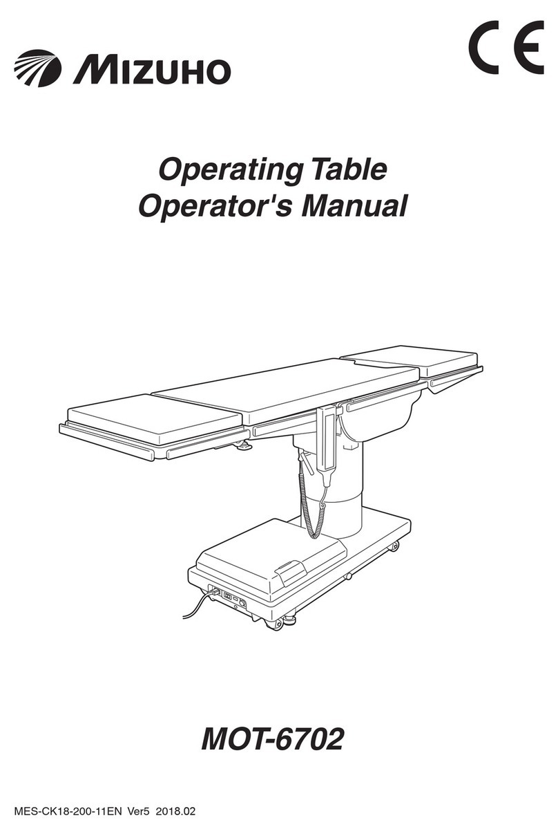
Mizuho MOT-5602BW User manual

Operating Table MOT-5602BW
Operator's Manual
This operating table is designed for medical operations. Using this operating table for any
other purpose other than this intended use may cause serious injury.
The operator and the person in charge of the maintenance of this operating table must read
this operator's manual thoroughly and understand the contents before operating, inspecting,
adjusting and maintaining it.
Keep this manual for reference in a place where is readily accessible.
MES-CK18-450-10EN Ver.6 2023-07-14

Table of contents
1. Introduction ………………………………………………………… 1
1.1 This manual ……………………………………………………………………… 1
1.2 Intended use and this product ………………………………………………… 1
1.3 Accessories ……………………………………………………………………… 2
2. Safety precaution ………………………………………………… 3
2.1 Read thoroughly before using ………………………………………………… 3
2.2 Labeling ………………………………………………………………………… 8
3. Section Introduction ………………………………………………12
3.1 Main unit …………………………………………………………………………12
3.2 Hand controller …………………………………………………………………13
3.3 Foot switch (optional) ……………………………………………………………14
4. Operation ……………………………………………………………15
4.1 Installation and battery charging ………………………………………………15
4.2 Turningon/othepower ………………………………………………………20
4.3 Operating the emergency stop switch…………………………………………23
4.4 Fixingandunxingtheoperatingtable ………………………………………24
4.5 Tilting the tabletop laterally ……………………………………………………25
4.6 Trendelenburg ……………………………………………………………………26
4.7 Back section up/down …………………………………………………………28
4.8 Changing the tabletop height …………………………………………………29
4.9 Sliding the tabletop………………………………………………………………30
4.10 Flexingorreexingthetabletop ………………………………………………31
4.11 Return to level ……………………………………………………………………33
4.12 Adjusting the head section ……………………………………………………34
4.13 Adjusting the leg section ………………………………………………………36
5. Maintenance and inspection ……………………………………40
5.1 Inspection before and after use ………………………………………………40
5.2 Periodic replacement parts ……………………………………………………42
5.3 Version information of the software ……………………………………………42
6. Specication ………………………………………………………43
6.1 Specicationtable ………………………………………………………………43
6.2 External view ……………………………………………………………………45
7. Troubleshooting ……………………………………………………46
7.1 When the hand controller cannot be used ……………………………………46
7.2 When the brake cannot be released …………………………………………47
8. Before contacting for repairs ……………………………………48
App.-1 Electromagnetic Compatibility ………………………………50
App.-2 Glossary……………………………………………………………53

1
1
Introduction
1. Introduction
1.1 This manual
Thismanualcontainsinformationforsafelyandeectivelyusingthisproduct.
Before operating this product, read this manual thoroughly to understand how to operate and inspect the
product.
Failure to follow these instructions could lead to serious injury.
The safety information is categorized as per the following so that the contents of warnings and cautions, and
the details of warnings and cautions which are labeled on the product may be comprehended.
WARNING
If this indication is ignored and the product is incorrectly used, serious injury or
death may result.
CAUTION
If this indication is ignored and the product is incorrectly used, injury and/or damage
to property may result.
NOTE
This notice notes additional information on the product’s functions.
The warning and caution notices on this manual relating to operating and inspecting, apply to the intended
use (surgical operations) of this product.
If the product is used for purposes other than surgery, the user is responsible in regard to safety for
performing operations and inspections which are not contained in this manual.
1.2 Intended use and this product
This product is the operating table on which a patient is placed for surgical operations.
The product is intended to support a patient during surgical operations.
In conforming with the objectives of surgery, the product is equipped with features for adjusting its height,
and for freely changing and setting the patient’s body position.
The product uses both medical grade outlets and batteries as power sources.
This product is to be used by health care professionals, including but not limited to surgeons, nurses and
biomedical technicians.

2
1
Introduction
1.3 Accessories
Standard components and accessories
Hand controller
Operator’s manual
Flame-Retardant and Waterproof Pads (SUSANO Pad)
(for Head Section Type A, Back and Seat Section Type C,
Double Leg Section Type B)
Main unit
Power cord
Optional
Foot switch

3
2
Safety precaution
2. Safety precaution
2.1 Read thoroughly before using
In using this product, carefully read the following warnings and cautions, and make sure to observe them.
Any serious incident that has occurred in relation to the device should be reported to the manufacturer and
the competent authority in which the user and/or patient is established.
(4) (5)
(3)
(2)
(6)
(1)
(1) Head section and leg section
WARNING
Do not step or sit on the head section or the leg
section(s).
The operating table may tip over resulting in injury.
CAUTION
Before lowering the table or placing it in a reverse
Trendelenburg position, check if there are any devices
under the leg section.
If the leg section comes in contact with devices and it is
subjected to excessive force, the operating table may be
damaged.
CAUTION
When transferring a patient from the operating table (Fig. a) or changing a patient’s
body position (Fig. b), do not apply excessive force on the head section or leg section.
The operating table may get deformed or damaged.
Fig. a
Head section Leg section
Fig. b
Head section Leg section

4
2
Safety precaution
(2) Hand controller
WARNING
• Do not forcibly pull the hand controller cord.
• Do not subject the hand controller to strong shocks. The hand controller may get
damaged.
(3) Upper area of the base cover
CAUTION
Do not put any object on the cover.
When the table moves downward, or into the
Trendelenburg or the lateral tilt position, the slide
cylinder may come in contact with the object and get
damaged. Also, because the cover has a magnetic
component inside, any objects such as a magnetic card,
ifputonthecover,maybeaected.
(4) Power cord and power connector
WARNING
• Do not place any heavy objects on the power cord.
• Do not roll over the power cord with a castered device.
• Do not forcibly pull the power cord.
• Do not place any objects in the place where the power
cord is to be unplugged from the medical grade outlet,
which would obstruct it from being unplugged.
• Takewaterproongmeasuressuchascoveringthe
power connector with a plastic sheet, etc. so that
liquidsdonotinltrateinsideofthepowerconnector.
Ifliquidsinltrateinsideofthepowerconnector,it
maycausereordamage.
Power cord
(5) Installation of the operating table
WARNING
• Do not install the operating table
onanunevenoor.
• Do not place a pad under the
base for raising the operating
table. The operating table may
tip over resulting in injury.
Uneven floor Pad
(6) Table pad
WARNING
Make sure to always securely attach the table pads to the operating table so that they
donotcomeo.Thetablepadsmaycomeo,andthepatientmaygetinjured.

5
2
Safety precaution
CAUTION
• Attach the table pads straight along the Velcro fastenings from the edges. Attach
especially long table pads while holding them with your hands so that the surfaces
do not get wrinkled. If the table pads rise up or buckle, they may get deformed or
damaged.
• Do not apply tape, etc. directly on the table pads. Otherwise, they may get damaged.
• Placeandstorethetablepadsinatplaces.Leaningorbendingmaygetdeformed
or damaged.
• Do not store operating table accessories or other medical devices, etc. on the table
pads. Otherwise, they may get deformed or damaged.
• The table pads maintain waterproofness when they are properly attached in their
usage. If the table pads are attached other than the proper placement method in
theirusage,andliquidsinltrateinside,itmaycausedegradation.
• When cleaning the table pads, take care not to get liquids on the fasteners. If liquids
getonthewaterprooffasteners,wipethemoquickly.
If the waterproof fastener gets wet and the liquids
inltrateinside,itmaycausedegradation.
• Do not open the table pads waterproof fastener.
Ifliquidsinltrateinside,itmaycausedegradation.
Patient's position during surgical operation
WARNING
Position the patient's body 10 mm (0.39 in) or more away from the metal side rail. The
side rail may produce high temperatures due to the usage of electric scalpels, etc.,
which may result in a burn injury.
z Positioning the patient
Follow the steps below to position the patient.
1. Attach the accessory table pads onto the tabletop with their Velcro fastenings aligned
with each other.
2. Put the patient on the table pads. (Do not reverse the head side and the leg side and put
the patient on them.)
3. Position the patient according to the purpose of the surgical operation.
CAUTION
Have the person who operates the operating
table to operate it in a position where the
emergency stop switch can be immediately
pressed, and the patient’s condition can
constantly observed.
180°
Back section
Head section
Operator
position
Patient’s
head
Waterproof
fastener

6
2
Safety precaution
Other
WARNING
●Prohibited
• Do not disassemble and/or modify the operating table. Otherwise, malfunction may
occur.
●Patient position
• When using the tabletop or accessories to secure a patient’s body position, always
observe the patient’s condition.
Being in the same position for long periods of time causes neuroparalysis or
bedsores.
●Other medical electrical equipment to be used together with the operating table
•Whenusingahigh-frequencysurgicalequipmentand/oracardiacdebrillator
etc. with the operating table, refer to their operator's manual provided by the
manufacturers and observe the precautions and usage. Improper precautions
and usage may cause the operator or the patient to get burned and/or devices to
malfunction.
• When using medical electrical equipment etc. with the operating table, check
that the operating table does not malfunction before using it. Electromagnetic
interference may result in malfunctioning of the operating table.
●Weight capacity
• Do not apply loads which exceed the weight capacity (total of the patient and
accessories)*. The operating table may not function, which may result in failures.
* Elevation: 250 kg (550 lbs) / Operations other than elevation : 250 kg (550 lbs)
●Preventive maintenance and inspections
• Make sure to inspect and maintain the operating table before and after use. The
operatingtablemayrequirereplacementofthepartsduetosignicantwear,
deterioration, and/or breakage depending on the usage period and frequency of
use.
• For preventive maintenance and inspections, contact your distributor or Mizuho
directly.
●Antistatic measure
•Donotusetheoperatingtableonoorsand/orwithaccessoriesthatdonot
possess static electricity countermeasures. This may impede surgical operations.
CAUTION
●Devices and accessories used together with this product
• Before using other devices or accessories, thoroughly read the instruction manual
ofthedevicesandmakesurethattheoperatingtableisnotaectedadversely.
Beforettingonaccessoriesfromthirdpartycompanies,contactyourdistributoror
Mizuho.Someaccessoriescannotbettedon.
• While operating the operating table, check the position of other devices or the
accessories used with them. They may come in contact with each other during the
operation, the operating table, devices and/or accessories may get damaged.
•For hygiene, be sure to use sterilized drapes on the areas on this product where
the patient comes into contact with it.

7
2
Safety precaution
CAUTION
●Cleaning and disinfection
• After using the operating table, make sure to follow the steps below to clean up
and disinfect the operating table.
1.Turnothepoweranddisconnectthepowercordfromthemedicalgradeoutlet.
2. Detach all the table pads from the operating table.
3.Usealint-freeclothsoakedwithpropervolumeofdisinfectanttowipeothe
upper, side, and back side of the table pads.
4. As with step 3, disinfect the surfaces of the tables and side rails.
5.Wipeotheoperatingtablewithacleandryclothwithin15minutesafter
disinfecting it.
• Make sure to use Mizuho authorized disinfectants. The disinfectants are as shown below.
a) Sodium hypochlorite 0.1% (halogen containing compound)
b) Hypo Alcohol (iodine color removing agent)
c) Chlorhexidine (chlorhexidine gluconate 0.5%)
d)
Benzalkonium chloride (invert soap 10%)
e) Povidone iodine
f) Ethanol 80%
g) Hydrogen peroxide
h) Isopropyl alcohol (IPA)
●Moving and transporting
• Do not move the operating table with a patient on it.
• Follow the procedures below to move the operating table.
* Before moving the operating table, disinfect the entire operating table in order to
prevent infection.
1.Turnothepoweranddisconnectthepowercordfromthemedicalgradeoutlet.
2.Checkifthehandlesandleversareinxedpositions,andeachsectionisxed
rmly.
3. Unlock the brakes, and move the operating table.
*
Do not move the operating table by pulling on the head section or the leg section.
• The operating table should be transported with the following conditions met.
1.Disinfect the entire operating table before transporting it.
2.Take measures to prevent it from tipping over, such as lowering the tabletop to
the bottom position.
3.Actuate the brake.
4.Suitably position cushioning on the product to prevent it from getting damaged
during transport.
5.Store the product in a container so that it does not get exposed to dust, and the
weather.
●Disposal
• In accordance with the European Union Waste Electrical and Electronic Equipment
(WEEE) Directive, all electrical components and batteries must be disposed of in
accordance with local regulations. Please contact your local distributor for proper
disposal.
• Pay special attention to the following disposals:
a) Hydraulic Fluid
b)LeadAcidBatteries

8
2
Safety precaution
2.2
The operating table is labeled at the locations shown as below. Before use, make sure to understand the
contents of the labels.
Warning and Caution labels
(1) C655650 (2) C655608 (3) C653624
(6) C656740 (7) C655803
(9) C653614
(4) C655732 (5) C655649
(8) C657333
(1) (2)
(9)
(8)
(7)
(4)* (3)*
(5)
(6)
*: Applied on both sides.

9
2
Safety precaution
Other labels (1/2)
(10) C600516 (11) C655646 (12) C600020
(13) C655648 (14) C653515
(16) C600559
(15) C653516
(17) C653513 (18) C642002
(19) C655683
(19) (11)*
(10)*
(13)
(14)
(15)
(12)*
(18)
*: Applied on both sides.
(17)
(16)
YYYY-MM-DD

10
2
Safety precaution
Other labels (2/2)
(20) C653620 (22) C655692 (ASIA)
C655690 (EU)
or
C655687 (US)
or
(23) C655691 (ASIA)(21) C646067 (ASIA)
(27) PIN 558K8M3
(26) PIN 558K8M4
(25) PIN 558K6M7
(24) PIN 558K5M1
C655689 (EU)
or
C655686 (US)
or
C646070 (EU)
or
C646073 (US)
or
558K5M1 558K6M7
558K8M4 558K8M3
(20) (20) (20) (20)
(27)
(21)
(24) (25) (26)
(22) (23)
(20)

11
2
Safety precaution
Symbol mark for labeling
Symbol Description Labelno.
Indicates a possibility of injury or even death if operates the
table without following the warning
(1) (2) (3) (4) (5) (6)
(7) (8)
General prohibition sign (6)
General mandatory action sign (6)
Emergency stop (9)
Refer to the operator's manual (6) (9) (13) (18) (19)
Indicates AC power supply (18)
Enclosure Class (Splash-proof) (18)
Serial Number (18)
Catalogue Number (18)
Indicates waste disposal information (18)
European authorized representative (18)
Medical Device (18)
Equalization terminal (17)
Indicatesprotectionagainstelectricshockand
defibrillator(Class B) (20)
Debrillation-proofTypeBappliedpart (24) (25) (26) (27)
Date of manufacture (18)
Manufacturer (18) (24) (25) (26)
(27)
Conforms to BS 7177:2008 for medium hazard (24) (25) (26) (27)

12
3
Section Introduction
3. Section Introduction
3.1 Main unit
Equipotential terminal Foot switch connector (*2)
Power connector Power switch
Battery indicator
Fig. A
Table pads
Leg section (*1)
Hand controller
Seat section
Back section
Emergency stop switch
Head section (*1)
Leg section flexing lever
Leg section fixing handle
Auxiliary switch
Caster
Head section fixing handle
Side rail
Head section
flexing lever
Side frame
Slide cylinder
Column
Base
Hand controller connector
BrakeFig. A
Power cord
Emergency brake release knob
*1: The head section and the leg section can be detached.
*2: The foot switch is optional.

13
3
Section Introduction
3.2 Hand controller
TABLE UP
ENERGIZE ON/OFF
PRESS TO
LOCK BRAKES
LEVEL
BRAKE UNLOCK
REFLEX
FLEX
SLIDE HEAD SLIDE FOOT
TABLE DOWN
BACK UP BACK DOWN
TILT LEFT TILT RIGHT
REV. TREND.
POWER BATT.PILOT
MOT-5602BW
TREND.
Pilot lamp
Lateral tilt: Left down
Back section up
Table up
(Lock operating table)
Slide to head
Flex: Center up
Brake unlock
E switch
Battery lamp
Trendelenburg: Head down
Lateral tilt: Right down
Back section down
Table down
Slide to foot
Reflex: Center down
Return to level
Power lamp
Power ON/OFF switch
Reverse Trendelenburg:
Head up
NOTE
• The switches other than the E switch continue to function while being pressed.
• About 7 minutes of halting will be needed when operating the table continuously for about 3 minutes.
If the motor gets overheated you will not be able to operate the table. When overheat occurs, about 60
minutes of rest will be needed to operate the table as usual.
• If
ENERGIZE
is pressed, the pilot lamp lights up for 3 seconds. While the lamp is lit, pressing any function switch
activates its function.

14
3
Section Introduction
3.3 Foot switch (optional)
Table up Table down Trendelenburg:
Head down
Reverse
Trendelenburg:
Head up
Lateral tilt:
Left down
Lateral tilt:
Right down

15
4
Operation
4. Operation
4.1 Installation and battery charging
CAUTION
• Use the equipotential wire to ground the equipotential
terminal to the medical grounding terminals.
Prepare the equipotential wire yourself.
• When moving this product, carry it out with two or
more persons.
Equipotential wire
Equipotential
terminal
Installing the operating table
1. Movetheoperatingtabletoaatarea.
2. Check the battery lamp.
Ifthebatterylamp(orange)onthehandcontrollerashes,batterychargingisrequired.
TABLE UP
ENERGIZE ON/OFF
PRESS TO
LOCK BRAKES
LEVEL
BRAKE UNLOCK
REFLEX
FLEX
SLIDE HEAD SLIDE FOOT
TABLE DOWN
BACK UP BACK DOWN
TILT LEFT TILT RIGHT
REV. TREND.
POWER BATT.PILOT
MOT-5602BW
TREND.
Battery lamp
(Orange・
flash)
3. If the battery indicator shows empty (red), battery charging is required.
BATTERY INDICATOR
E F
Red・light up

16
4
Operation
Installation space
This product requires the installation space shown as below.
2.5m (98.43in)
or more
2.5m (98.43in)
or more
2.5m (98.43 in)
or more
2.5m (98.43 in)
or more

17
4
Operation
Charging the battery
CAUTION
• Connect the product to the power source provided
with the protective grounding to prevent the risk of
an electrical shock.
• Make sure to use the dedicated power cord with
the "MIZUHO" logo.
• Before inserting the power cord into the power
connector, check that the power connector does
nothaveanyuidinitnorisdusty.
• Whenturningothepowercompletely,disconnect
the power cord from the medical grade outlet.
1. Connect the power connector of the product and the
medical grade outlet with the power cord.
Medical grade outlet
Power cord
Power connector
2. When turning on the power switch, battery charging starts.
While charging, the battery indicator sequentially lights up orange.
3. When the battery indicator sequentially lights up orange
and green, charging is completed.
E FE FE F
BATTERY INDICATOR
Charging in progress Charging completeNeeds charging
Orange Orange Green
Red
(Red light up) (Orange light up in order) (Orange and Green
light up in order)
NOTE
• Make sure to charge the
battery when initially using
the purchased product, or
when it has not been used
for a long time. The battery
naturally discharges itself
when it is not being used
and is being stored.
• If the battery lamp on the
handcontrollerashesor
the battery indicator on the
lower part of the operating
table lights up only red
while using the operating
table with the battery
power, charge the battery
immediately. When the
battery is discharged, only
the AC power is available
and will not be able to use
the battery power.
• The operating table battery
replacement time is about
2 years. Once it reaches its
replacement time, request
your distributor or Mizuho
for a battery replacement.
• The life-span for the battery
varies greatly depending
on operating conditions.
The battery could degrade
quicker if charging and
discharging the battery are
repeated frequently after
using the operating table
for short operations.
• It is recommended that you
charge the battery once a
week on weekends, since
it takes about 24 hours to
fully charge the battery.
• If the battery is discharged
soon even after charging, the
battery may be degraded.
Request repairs from your
distributor or Mizuho.
• While the battery is being
charged, you can operate
the operating table by using
ON/OFF
on the hand controller.

18
4
Operation
Attaching the hand controller
1. Align the connector with the guide and insert it into the
receptacle properly.
Insert
the connector
Detaching the hand controller
1. Turn the connector ring in the direction of the arrow until it
stops.
2. Pull up the connector.
1. Turn the ring
2. Pull up
the connector
Other manuals for MOT-5602BW
2
Table of contents
Other Mizuho Indoor Furnishing manuals
Popular Indoor Furnishing manuals by other brands

BDI
BDI Sequel 6005 Assembly instructions

ROOMS TO GO
ROOMS TO GO SH235FBGE-1 Assembly instruction

Safco
Safco PanelMate 4158 Assembly instructions

VIA Technologies
VIA Technologies Eclipse 646 Adjustment guide

VECELO
VECELO KHD-XF-ST13 Assembly instructions

eliving FURNITURE
eliving FURNITURE Raku Series Assembly instructions

Mocka
Mocka Denham Assembly instructions

realspace
realspace 563-375 Assembly instructions and warranty information

Mocka
Mocka Inca Three Drawer Assembly instructions

Dwell
Dwell Notch 142878 manual

Snow Peak
Snow Peak Single Action Round Table M instruction manual

DURAVIT
DURAVIT Qatego QA 7083 Mounting instructions