Mizuho MOT-6702 User manual

Operating Table
Operator's Manual
MOT-6702
MES-CK18-200-11EN
Ver5
201.

Page 1
TABLE OF CONTENTS
Title Page
WARRANTY··················································································································································3
EQUIPMENT LABELS ··································································································································4
SAFETY & HEALTH SYMBOLS····················································································································5
TABLE SPECIFICATIONS·····························································································································7
SPECIAL USER ATTENTION························································································································9
SECTION I INTRODUCTION ···················································································································16
1-1. General·········································································································································16
1-2. Power Requirements ····················································································································16
1-3. Pendant Control Unit ····················································································································17
1-4. Floor Lock/Brake System··············································································································18
SECTION II OPERATION ·························································································································19
2-1. Electrical Power ····························································································································19
2-2. AC 100 - 240 V Operation·············································································································19
2-3. Battery Operation ·························································································································20
2-4. Automatic Shut-Off························································································································20
2-5. Charging the Battery·····················································································································20
2-6. Positioning Functions····················································································································21
a. Floor Lock/Brake System ···········································································································22
b. Trendelenburg ····························································································································23
c. Lateral Tilt ··································································································································24
d. Back Section ······························································································································24
e. Elevation ····································································································································25
f. Leg Section································································································································25
g. Flex Positioning··························································································································25
h. Kidney Lift ··································································································································26
i. Return To Level ··························································································································26
j. Beach Chair ·······························································································································26
2-7. Emergency Switch························································································································26
2-8. Emergency Back-up Controls ·······································································································27
2-9. Emergency Brake Release ···········································································································27
2-10. Head Section ······························································································································28
2-11. Leg and Back Section Removal ··································································································29
2-12. Table Top Rotation ······················································································································29
2-13. Positioning ··································································································································30
SECTION III MAINTENANCE···················································································································32
3-1. Routine Inspections 㺃Performed Daily by Operator····································································32
3-2. Preventive Maintenance ···············································································································32
3-3. Cleaning Recommendations·········································································································33
3-4. Operator Troubleshooting ·············································································································35
3-5. Maintenance Matrix ······················································································································35
3-6. Service ·········································································································································37
3-7. Disposal Instructions ····················································································································37

Page 2
TABLE OF CONTENTS (continued)
Title Page
SECTION IV ELECTROMAGNETIC EMISSIONS····················································································38
Although current at time of publication, MIZUHO's policy of continuous development makes this manual sub-
ject to change without notice.

Page 3
WARRANTY
MIZUHO Corporation will repair defective parts of this product without charge for one year from the
date of delivery/installment except for cases of damage caused by a third party's repair, act of
nature, improper use or damage on purpose. All other warranty terms and conditions are subject to
regulations of MIZUHO Corporation.

Page 4
EQUIPMENT LABELS

Page 5
SAFETY & HEALTH SYMBOLS
Symbol Description
Used On
Product
Used In
Manual
NOTE Indicates important facts or helpful hints ۑۑ
ISO 7010-W001 General warning sign (WARNING, CAUTION) ۑۑ
IEC 60417-5840
Type B applied part ۑ
IPX4
IEC 60529 Enclosure class (Splash-proof) ۑ
WEEE
Indicates waste disposal information ۑ
ISO 7010-M002
Refer to instruction manual ۑ
IEC 60417-5032 Alternating current ۑ
ISO 15223-1-5.1.1
Manufacturer ۑۑ
ISO 15223-1-5.1.2
AUTHORISED REPRESENTATIVE IN THE
EUROPEAN COMMUNITY ۑۑ
ISO 15223-1-5.1.6 Catalogue number ۑ
ISO 15223-1-5.1.7 Serial number ۑ
IEC 60417-5021
Equipotentiality ۑ
Blue

Page 6
SAFETY & HEALTH SYMBOLS
Symbol Description
Used On
Product
Used In
Manual
ISO 7010-P001
General prohibition sign ۑ
ISO 7010-M001
General mandatory action sign ۑ
IEC 60417-5638
Emergency stop ۑ
IEC 60417-5019
Protective earth (ground) ۑ
IEC 60417-5841
Defibrillation-proof Type B applied part ۑ
IEC 60417-5017
Earth (ground) ۑ
Red
Blue

Page 7
TABLE SPECIFICATIONS
240 mm 464 mm 485 mm 585 mm
TOP VIEW
SIDE VIEWFRONT VIEW
1926 mm
943 mm
150 mm
500 mm
483 mm
MAX
1053 mm
MIN
600 mm
364 mm
90°
60°
75 mm
Electrical Specifications
Power Requirements: 100 - 240 VAC, 50 - 60 Hz, 400 VA
Current Leakage: Less than 500 micro amps
Power Cord : 4.5 m w/hospital grade connector (removable)
Duty Cycle: 3 min on, 7 min off
Battery Power: 24VDC (12Vx2) <model: FML12170-12V17Ah/Furukawa Battery>
Classification
Class I Equipment
Applied Parts: Table Top/Type B Applied Parts Mattress/Defibrillation Proof, Type B Applied Parts
IPX4 Rated
㺃Equipment not suitable for use in the presence of flammable anesthetic mixture with AIR,
OXYGEN or NITROUS OXIDE.
㺃This product does not intend to sterilize.
Environmental Condition
Condition of Use Condition of Transport and Storage
Ambient Temperature 10 - 40°C -10 - 50°C
Relative Humidity 30 - 75% 10 - 85%
(No Condensation)
Atmospheric Pressure 700 - 1060 hPa 700 - 1060 hPa
Operating altitude㸸2000 m max above sea level

Page 8
TABLE SPECIFICATIONS
Mechanical Specifications
Maximum Lifting Capacity: 540 kg
Maximum Articulating Capacity: 450 kg
The height and width to be able to pass by: Height 10 mm/Width 80 mm (0.4m/s±0.1m/s)

Page 9
SPECIAL USER ATTENTION
Prior to use, all personnel that may operate this
table must be instructed in the correct opera-
tional procedures. This table is designed for use
by trained and qualified personnel for human
medical purposes only.
Initial use should not begin until after the users
have been instructed by the manufacturer's
representative.
A routine instructional program must be imple-
mented by the facility for proper usage instruc-
tions for all personnel that may operate this ta-
ble.
The maximum lifting capacity of the 6702 table
is 540 kg and the maximum articulation weight
capacity is 450 kg. When lifting or articulating
large patients, pay close attention to the patient
position as well as the positioning guidelines
and limitations listed in the operation instruc-
tions.
The extreme positioning capabilities of the 6702
Table requires special attention for possible inter-
ference points when using multiple function posi-
tioning. As with the operation of any surgical table, a
certain amount of care should be exercised to posi-
tion the patient safely. Although the thick pads and
sheets substantially protect the patient, pinch points,
located at the joints of the top section should always
be considered. BE SURE THAT THE ARMS,
HANDS AND FINGERS OF THE PATIENT AND
THOSE OF THE OPERATING ROOM
PERSONNEL ARE CLEAR OF ALL MOVING
PARTS BEFORE MOVING THE TABLE. Proper re-
straints should always be used for patient safety.
Certain accessories such as the Uro-Drain Tray,
Armboards and X-Ray top can be damaged when
changing the position of the table top sections. Al-
ways look first to see if a desired movement is going
to interfere with any accessories in use.
The operator has the ultimate responsibility of pre-
venting damage to the table and surrounding
equipment or possible injury to the patient or staff.
The operator must ensure proper positioning is
maintained to prevent compromising respiration,
nerve pathways or circulation.
In general, common sense will dictate when there is
a potential hazard.
The following precautions should be reviewed
by all personnel prior to operating the table.
WARNING
Indicates a possibility of personal injury.
CAUTION
Indicates a possibility of damage to
equipment.
NOTE
Indicates important facts or helpful
hints.
This equipment is intended for use by healthcare
professionals only. This equipment may cause radio
interference or may disrupt the operation of nearby
equipment. It may be necessary to take mitigation
measures, such as re-orienting or relocating the
table or shielding the location.
Do not use worn or damaged accessories, they
represent an injury hazard.
Remove possible obstacles before lowering or tilting
the operating table.
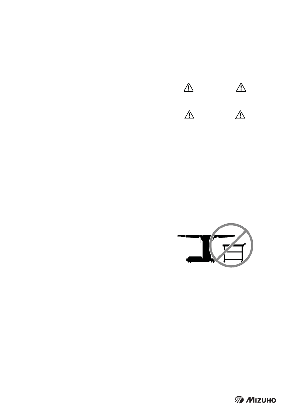
Do not place objects on the base of the table, a
danger of damage exists during positioning.
Use caution when articulating the table top, pinch
hazards exist.

Page 10
SPECIAL USER ATTENTION
WARNING
Always inspect product prior to use to
ensure safe and correct operation. Any
product deemed to be malfunctioning
should be removed from service and
labeled inoperable. Refer all service to
a qualified MIZUHO service repre-
sentative.
NOTE
If any buttons on the control unit are
pressed continuously for longer than 10
minutes, the thermal protector of the
pump motor will actuate and the opera-
tion of the table will be stopped. The
thermal protector will reset in approxi-
mately 30 minutes.
NOTE
The operating table a built-in
self-diagnosis function to check if the
operating table and control unit work
properly.
1. Connect the power cord.
2. Press the BATTERY ON/OFF button
on the pendant control.
3. Press the ENERGIZE button and
then one of the function buttons on
the pendant control. If two green
battery indicators are lit, the pendant
control works properly.
NOTE
Activating any function button will acti-
vate the brake system. Using the
TABLE UP function to set the brakes
provides a visual assurance that the
brakes are locked without altering the
table position, except when emergency
brake is released.
WARNING
Prior to operating the table, observe all
table caution labels and review the
SPECIAL USER ATTENTION section in
the front of this manual.
WARNING
Possible explosion hazard exists if table
is used in the presence of
FLAMMABLE ANESTHETICS.
NOTE
An equalization grounding terminal is
located under the main power panel.
This is provided as an alternate path-
way to reduce the risk of static shock
hazards. Always follow recommended
grounding procedures to ensure patient
and staff safety.
WARNING
To avoid the risk of electric shock, this
equipment must only be connected to a
supply main with Protective earth.
Power Cord has to be used the one
which has a logotype of MIZUHO.
WARNING
Please don't position the surgical table
in such way that the operator has diffi-
culty to disconnect the Equipment by
plug or appliance outlet.
NOTE
The table will operate correctly on bat-
tery power with the power cord con-
nected to a wall outlet or disconnected.
NOTE
Battery Operation must be turned OFF
at the pendant control. It can not be
turned Off using the main power switch.
NOTE
Turning the Main Power Switch ON will
change the table operation to 100 - 240
VAC power.

Page 11
SPECIAL USER ATTENTION
NOTE
When the red light starts to blink (indi-
cating low power in battery) the table
will operate for approximately 5 contin-
uous minutes, typically long enough to
use the table for the rest of the day.
NOTE
The charging system operates ONLY
when the table is in AC 100 - 240 V op-
eration mode. While charging a battery,
the operation of Power on/ off can be
performed with a BATT ON/OFF switch.
NOTE
The table can be operated on 100 - 240
VAC power while the battery is being
recharged.
WARNING
If the table is stored for a period greater
than 6 months, the batteries should be
removed and stored in a dry, clean
condition at a storage temperature of
68°F (20°C). Batteries should be re-
charged every 6 months of product
storage.
WARNING
A operator of operating table has to
perform his/her activity at the position
which is indicated in below drawing
where he/she can push the emergency
stop switch immediately and observe
his/her patients.
WARNING
xPlease confirm that the operating table
is fixed stably after applying the brakes.
xDO NOT unlock brakes when patient is
on the table. An uneven patient weight
load may cause instability.
xIf circumstances demand table brakes
to be unlocked, the patient must be
centered and evenly distributed on the
table top (i.e. supine or prone position)
with the table lowered to its lowest
height position. The maximum patient
weight should not exceed 230 kg. Table
top rotation must be in normal orienta-
tion, that is, the back section over the
long end of the table. Patient's head
must be on the head section. Head
section must be attached in its normal
orientation to the table's back section.
xPrior to unlocking brakes, check for ob-
structions on the floor that might pre-
vent the table from moving smoothly to
new location. Relock the brakes imme-
diately once the final position is
reached and before commencing sur-
gery. Table brakes should remain locked
at all times if patient weight exceeds
230 kg.
xDon't move a table with patient carried.
There is a risk that patient may fall and
injure or staff may injure.
xDon't move a table with heavy object
carried. There is a risk that heavy object
may fall and damage or staff may injure.
NOTE
With an evenly distributed patient
weight load, all table positioning func-
tions will operate smoothly and quietly
with a patient weight of up to 450 kg.

Page 12
SPECIAL USER ATTENTION
NOTE
To prevent table damage, a safety in-
terlock limits Trendelenburg positioning
to 20° if lateral tilt positioning exceeds
20°. An audible alarm will sound.
WARNING
To maximize patient safety, utilize
proper restraint methods during ex-
treme Trendelenburg positioning.
NOTE
To prevent table damage, a safety in-
terlock limits lateral tilt positioning to
20° if Trendelenburg positioning ex-
ceeds 20°. An audible alarm will sound.
WARNING
In order to ensure the maximum safety,
whenever lateral tilt is operated, be sure
to utilize a restraint method. There is a
risk that a patient may fall from operat-
ing table.
NOTE
To prevent damage to the kidney lift, a
safety interlock prevents the back sec-
tion from going above horizontal if the
kidney lift is not all the way down. If the
kidney lift is raised, an audible alarm
will sound when the BACK UP button is
pressed.
NOTE
If back section is below horizontal,
BACK UP function is limited to 800
pound patient weight.
WARNING
The Leg section may hit the table base
or the floor if both the leg and elevation
systems are placed in their full down
position.
NOTE
When REFLEX button is activated, if
Kidney Bridge is up, the back section
will not go above horizontal.
NOTE
To prevent damage to the kidney lift, a
safety interlock prevents the kidney lift
from going up if the back section is
raised above horizontal. An audible
alarm will sound.
NOTE
Elevation and brake system functions
are not affected by the return to level
function.
CAUTION
Please use the emergency switch at the
urgent case only.
CAUTION
The Back Section/Kidney Lift safety in-
terlock is not operational when the
emergency back-up control switches
are used.
CAUTION
The EMERGENCY BRAKE LOCK
switch does not activate the brake sys-
tem timer. The switch must be held until
the brakes are completely locked, ap-
proximately 10 seconds.
NOTE
The emergency back-up control
switches will function when the table is
operating on 100 - 240 VAC power,
battery power, or turned off.

Page 13
SPECIAL USER ATTENTION
NOTE
xThe Emergency Brake Release Valve
must be closed and tightened (coun-
ter-clockwise) before activating any hy-
draulic function.
xIf the Emergency Brake Release Valve
has been operated, the BRAKE
UNLOCK button on the pendant control
will have to be pressed before brakes
will lock again.
NOTE
To make the Back Section easier to
handle, remove the Head Section and
X-ray Top prior to removing the Back
Section.
WARNING
Ensure that the Leg and Back sections
are properly engaged and secured to
pins before use to prevent injury.
NOTE
The Leg and Back sections are labeled
for proper orientation. The Leg section
cannot be installed on the Back section
pins.
NOTE
Normal table top position is with the
head (and back) section over the power
cord end of the base.
WARNING
Always lock the table top in position af-
ter rotation. DO NOT rotate the top with
an unevenly distributed patient weight
load as instability may result.
WARNING
xMake sure the TOP ROTATION LOCK
HANDLE is tightened and the brakes
are set before transferring the patient.
xExercise caution with the table top ro-
tated 90° to the base since an improp-
erly distributed patient load may cause
the table to be tipped over.
WARNING
Consult manufacturer's instructions
when using high frequency surgical
equipment, cardiac defibrillator and
cardiac defibrillator monitors. Improper
operation procedures might cause a
burn on an operators or patient, and
also cause the malfunction of the
product.
WARNING
xWhen a patient is put on a mattress and
his/her position is set up, a patient shall
be set up to more than 1 cm apart from
a side rail so that a patient dose not
touch on side rails (metal).
xThe mattress should be attached in
order not to come off while being in use.
WARNING
When an antistatic pathway is required,
the table has to be used on an antistatic
floor.
WARNING
The antistatic properties of the table are
dependent on the use of the original
pad set which was furnished with the
table or an alternate approved re-
placement.

Page 14
SPECIAL USER ATTENTION
WARNING
Certain accessories may limit weight
capacities. Check with your MIZUHO
representative.
WARNING
MIZUHO Products are guaranteed for
proper performance with the use of
genuine MIZUHO accessories.
Accessories and products not furnished
by MIZUHO have not been tested for
proper performance and safety. Such
applications or use are at the discretion
of the user to ensure patient and staff
safety.
CAUTION
xMIZUHO surgical tables are designed
to be used by trained healthcare pro-
fessionals only.
xPlace a patient on the table after a
70mm minimum thickness mattress is
certainly attached onto the table top for
safeness of a patient.
xAttach a mattress onto the table
properly in order not to slip off or come
off the table during operation.
xInstall a table board in order not to
recognize the fixing screws.
xPut a patient on the table after the mat-
tress is changed to proper position
when the mattress is found to be out of
proper position.
WARNING
Set up a patient's position in order not
to touch the metal parts like table board
or side rail of table top directly. Metal
part might cause a burn.
NOTE
xA mattress is an applied part.
xUsable mattresses are as following.
50005M2
672A6M1
360L8M2
Mattress's shape is suitable for each
table board.
xTag which indicates that a mattress is
an applied part and is made by
MIZUHO is attached on a mattress.
CAUTION
DO NOT use the table if any of the in-
spection points fail.
CAUTION
Caution should be taken when cleaning
the table to prevent excessive fluid en-
try into electrical connectors.
WARNING
Always follow the national blood-borne
pathogens standards for protective
clothing, including gloves, masks and
eye protection when cleaning the sur-
gical table.
CAUTION
Thoroughly read and follow the manu-
facturer's directions for all cleaning flu-
ids. DO NOT use cleaners containing
phenolics.
CAUTION
When using spray cleaners DO NOT
spray fluids directly into electrical re-
ceptacles or micro switches.

Page 15
SPECIAL USER ATTENTION
CAUTION
Before replacing pads on the table,
make sure the pads and all mating
surfaces are completely dry. Moisture
trapped between the pads and mating
surfaces may cause distortion of table
tops.
WARNING
xDO NOT dissemble the table. Unau-
thorized disassembling may cause
electric shock or malfunction.
xPlease contact your local distributor or
manufacturer for maintenance or repair.
The operating table should only be ser-
viced or maintained by a factory trained
personnel.
NOTE
Technical description of this product is
due to the Maintenance Manual.
The contents of Maintenance Manual
are as follows.
SECTION I HYDRAULIC SYSTEM
SECTION II MECHANICAL TABLE
ADJUSTMENTS
SECTION III HYDRAULIC
TROUBLESHOOTING
SECTION IV ELECTRICAL SYSTEM
SECTION V ELECTRICAL
TROUBLESHOOTING
Maintenance Manual can be obtained
only by the person who has had the
service training of MIZUHO.

Page 16
SECTION I INTRODUCTION
SIDE RAIL
HEAD SECTION
LOCKING KNOB
PENDANT CONTROL
STORAGE BRACKET
EMERGENCY
SWITCH
SERVICE
ACCESS COVER
MAIN POWER
SWITCH
EMERGENCY
BRAKE RELEASE
FLOOR/LOCK
BRAKE (4)
LEG SECTION
RELEASE LEVER
(RECESSED)
POWER
CORD
MATTRESS
PENDANT
CONTROL
LEG
SECTION
671DU03
SEAT
SECTION
BACK
SECTION
671DU04
HEAD
SECTION
562GU01
KIDNEY
SECTION
MATTRESS
MATTRESS
PIN 50005M2
Tokyo, Japan
PIN 360L8M2
Tokyo, Japan
PIN 672A6M1
Tokyo, Japan
Figure 1-1. 6702
1-1. General
a. Intend Use. This Product is intended for hold-
ing a patient on the surgical operation.
b. A place to use this product should be an operat-
ing room in the hospital.
c. The user of this product should be doctors or
nurses or medical engineers who have sufficient
knowledge of this product.
The 6702 Surgical Table is an electro-hydraulically
operated, general purpose surgical table. See figure
1-1.
The electro-hydraulic positioning functions operated
by the hand-held, push button, pendant control unit
are: Trendelenburg, lateral tilt, back section, eleva-
tion, leg section, flex/reflex, kidney lift, return to level,
beach chair and the floor lock/brake system.
Manual controls are provided for head section posi-
tioning, table top rotation, emergency brake release,
back section removal and leg section removal.
1-2. Power Requirements
The 6702 Surgical Table requires a 100 - 240 VAC,
50 - 60 Hz electrical power supply. The table is
equipped with a removable 4.5 m long power cord
with a three prong, hospital grade plug. The main
power ON/OFF switch is located on the electrical
panel on the front edge of the table base. See figure
1-2.
The battery charging indicator and foot control
connector are also located on the electrical panel.
POWER CORD
BATTERY INDICATOR
POWER SWITCH
FOOT SWITCH
EF
POWER
CORD
MAIN POWER
SWITCH
BATTERY
INDICATOR
FOOT CONTROL
CONNECTOR
Figure 1-2. Electrical Panel
ۻAccessories
yPOWER CORD
yPENDANT CONTROL
yMATTRESS
ۼDetachable parts
yHEAD SECTION
yBACK SECTION
yLEG SECTION

Page 17
SECTION I INTRODUCTION
1-3. Pendant Control Unit
The hand-held pendant control unit (figure 1-3) has
a non-slip rubber cover which assures a positive
grip during use. A spring clip hanger is located on
the back of the control for storage. When the Pen-
dant Control is not in use, it should be stored on a
convenient side or end rail. A bracket is located un-
der the table top next to the pendant control con-
nector for storage of the Pendant Control when the
table is not in use and during cleaning. See figure
1-4.
POWER
INDICATOR
SIDE RAIL
CLIP
FUNCTION
BUTTONS
Figure 1-3. Pendant Control Unit
PENDANT CONTROL
STORAGE BRACKET
TOP ROTATION
HANDLE
BACK
SECTION
SEAT
SECTION
Figure 1-4. Pendant Control Storage Bracket
The function push buttons are identified with abbre-
viated descriptions for all functions. See figure 1-5.
When illuminated the Trendelenburg and table up
buttons are red, the remaining buttons are all green.
AC100 -240 V POWER
ON INDICATOR LIGHT
(GREEN)
TRENDELENBURG
LATERAL TILT
RIGHT
BACK DOWN
TABLE DOWN
LEG DOWN
REFLEX
KIDNEY LIFT
DOWN
ENERGIZE
BEACH CHAIR
REVERSE
TRENDELENBURG
LATERAL TILT
LEFT
BACK UP
TABLE UP
(BRAKE LOCK)
LEG UP
FLEX
KIDNEY LIFT
UP
BATTERY
RETURN TO
LEVEL
BRAKE UNLOCK
Figure 1-5. Function Buttons
NOTE
If any buttons on the control unit are
pressed continuously for longer than 10
minutes, the thermal protector of the
pump motor will actuate and the opera-
tion of the table will be stopped. The
thermal protector will reset in approxi-
mately 30 minutes.
NOTE
The operating table a built-in
self-diagnosis function to check if the
operating table and control unit work
properly.
1. Connect the power cord.
2. Press the BATTERY ON/OFF button
on the pendant control.
3. Press the ENERGIZE button and
then one of the function buttons on
the pendant control. If two green
battery indicators are lit, the pendant
control works properly.

Page 18
SECTION I INTRODUCTION
1-4. Floor Lock/Brake System
The floor lock/brake system consists of four
self-leveling, hydraulic brake cylinders which raise
and support the table base off from the casters.
Press the TABLE UP button on the pendant control
to set the table’s brakes. An electronic timer will ac-
tivate the brake system until the brakes are com-
pletely set, approximately 8-10 seconds.
NOTE
Activating any function button will acti-
vate the brake system. Using the
TABLE UP function to set the brakes
provides a visual assurance that the
brakes are locked without altering the
table position, except when emergency
brake is released.

Page 19
SECTION II OPERATION
2-1. Electrical Power
The 6702 table will operate on either 100 - 240 VAC
or battery power.
WARNING
Prior to operating the table, observe all
table caution labels and review the
SPECIAL USER ATTENTION section in
the front of this manual.
WARNING
Possible explosion hazard exists if table
is used in the presence of
FLAMMABLE ANESTHETICS.
NOTE
An equalization terminal is located un-
der the main power panel. This is pro-
vided as an alternate pathway to re-
duce the risk of static shock hazards.
Always follow recommended grounding
procedures to ensure patient and staff
safety.
2-2. AC 100 - 240 V Operation
Use the following procedures to operate the table on
100 - 240 VAC power.
a. Make sure the Power cord is securely attached to
the table. To install the power cord, align the cord
connector with the base connector, insert the cord
and twist clockwise to lock the cord into the con-
nector. See figure 2-1. Plug the cord into a properly
grounded, Hospital Grade, 100 - 240 VAC outlet.
Make sure the power cord is routed to the outlet to
prevent it from being in the way of operating per-
sonnel. To remove the power cord, and pull the cord
connector out of the base connector.
WARNING
To avoid the risk of electric shock, this
equipment must only be connected to a
supply main with Protective earth.
Power Cord has to be used the one
which has a logotype of MIZUHO.
b. Activate the POWER SWITCH located on the
electrical panel. The switch will illuminate.
POWER CORD
BATTERY INDICATOR
POWER SWITCH
FOOT SWITCH
EF
MAIN POWER
SWITCH
BATTERY
INDICATOR
EQUALIZATION
GROUNDING TERMINAL
FOOT CONTROL
CONNECTOR
POWER
CORD
Figure 2-1. Electrical Panel
The pendant control buttons and the green AC 100 -
240 V, POWER indicator light located in the upper
right corner of the pendant control will illuminate.
See figure 2-2.
AC100 -240 V POWER
ON INDICATOR LIGHT
(GREEN)
Figure 2-2. Pendant Control
c. The table is now ready for 100 - 240 VAC opera-
tion.
d. When operating table is disconnected from
commercial power supply, a power supply cable has
to be pulled out from AC outlet.
WARNING
Please don't position the surgical table
in such way that the operator has diffi-
culty to disconnect the Equipment by
plug or appliance outlet.
Table of contents
Other Mizuho Indoor Furnishing manuals