MO-EL SW-UNM-8FE1GC-8POE User manual

SW-UNM-8FE1GC-8POE
8-Port 10/100Mbps + 1-Port Gigabit Combo POE
Unmanaged Ethernet Switch
User Manual
Version 1.0 | 5/15/2015

Table of Contents
Chapter 1 Product Introduction ................................................................................................ 1
1.1 Product Overview ............................................................................................................ 1
2.2 Features ............................................................................................................................ 1
3.3 Package Contents ........................................................................................................... 1
Chapter 2 External Component Description ......................................................................... 2
2.1 Front Panel ....................................................................................................................... 2
2.2 Rear Panel ........................................................................................................................ 3
Chapter 3 Installing and Connecting the Switch .................................................................. 4
3.1 Installation ......................................................................................................................... 4
3.1.1 Desktop Installation .............................................................................................. 4
3.1.2 Rack-mountable Installation in 11-inch Cabinet ............................................... 4
3.1.3 Power on the Switch ............................................................................................ 5
3.2 Connect Computer (NIC) to the Switch ........................................................................ 5
3.3 Switch connection to the PD .......................................................................................... 5
Appendix: Technical Specifications ........................................................................................ 6

1
Chapter 1 Product Introduction
Congratulations on your purchasing of the 8-Port 10/100Mbps + 1-Port Gigabit Combo
PoE Ethernet Switch. Before you install and use this product, please read this manual
carefully for full exploiting the functions of this product.
1.1 Product Overview
The Switch provides 8-port 10/100Mbps and 1-port Gigabit Combo, support all port
forwarding line speed. These PoE ports can automatically detect and supply power with
those IEEE 802.3at compliant Powered Devices (PDs). In this situation, the electrical
power is transmitted along with data in one single cable allowing you to expand your
network where there are no power lines or outlets, where you wish to fix devices such as
APs, IP Cameras or IP Phones, etc.
This Switch is easy to install and use. It requires no configuration and installation. With
desktop design, outstanding performance and quality, the 8-port 10/100Mbps Desktop
PoE Switch is a great selection for expanding your home or office network.
2.2 Features
Comply with IEEE 802.3, IEEE 802.3u, IEEE 802.3x, IEEE 802.3ab standards
Support 8 × 10/100Mbps Auto-negotiation Fast Ethernet RJ45 ports with 8 port PoE
function (port1-port8) and 1 Gigabit combo port
Supports PoE power up to 30W for each PoE port
Supports All power up to 140W
Supports PoE IEEE 802.3af and IEEE 802.3at compliant Powered Device (PD)
Supports IEEE 802.3x flow control for Full-duplex Mode and backpressure for
Half-duplex Mode
Support Store-and-Forward switching method
LED indicators for monitoring power, link, activity, PoE status
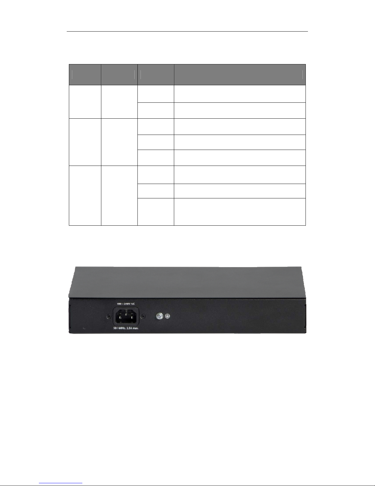
11 inch steel casing design, build-in power supply
3.3 Package Contents
Before installing the Switch, make sure that the following the "packing list" listed OK. If
any part is lost and damaged, please contact your local agent immediately. In addition,
make sure that you have the tools install switches and cables by your hands.
One 8-Port 10/100Mbps + 1-Port Gigabit Combo PoE Ethernet Switch
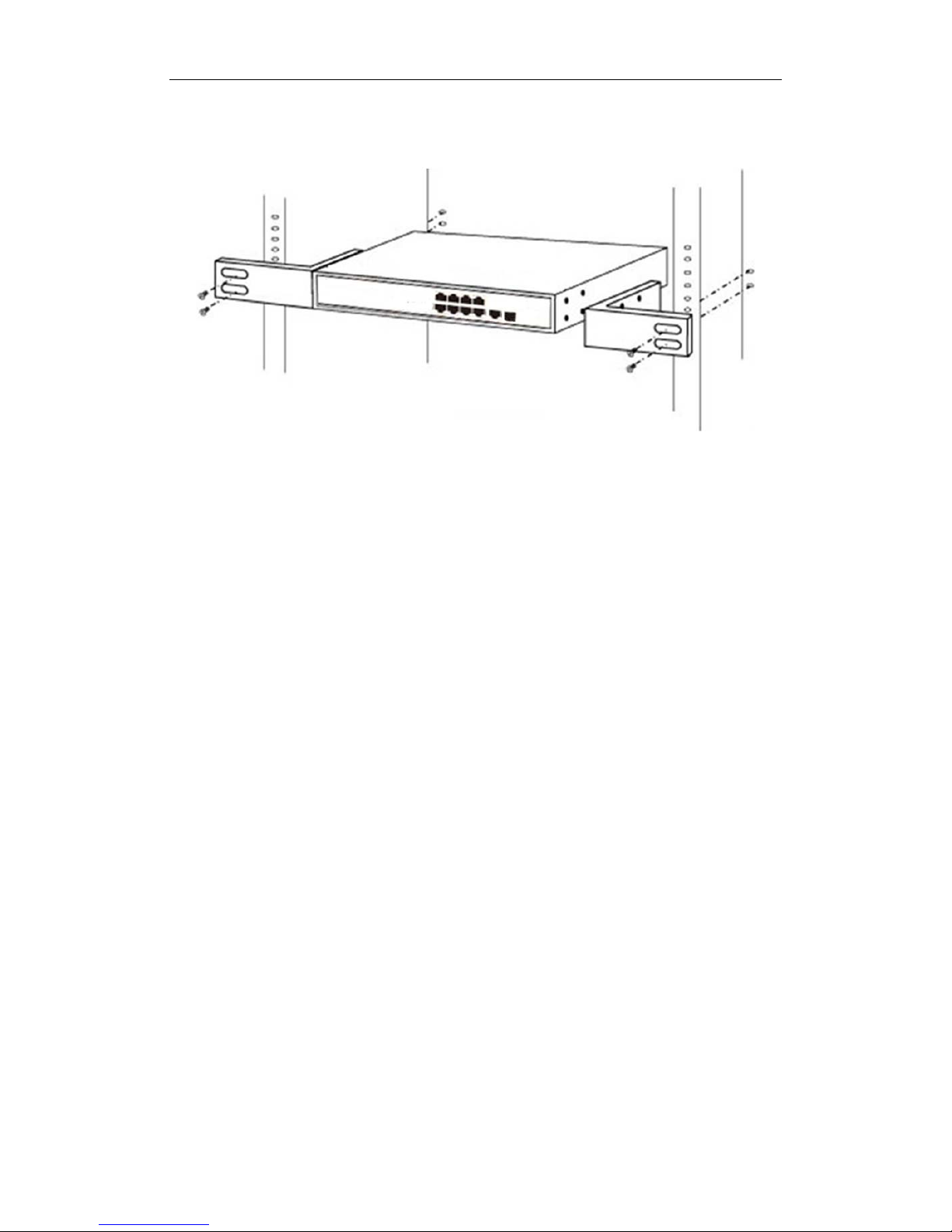
One Set of installation components
One AC power cord
One User Manual

2
Chapter 2 External Component Description
2.1 Front Panel
The front panel of the Switch consists of series of LED indicators, 8 10/100Mbps RJ-45
ports, 1 10/100/1000Mbps RJ45 port and 1 100/1000Mbps SFP port shown as below:
Figure 1 - Front Panel
10/100Mbps RJ-45 ports (1~8):
Designed to connect to the device with a bandwidth of 10Mbps or 100Mbps. Each has a
corresponding Link/Act and PoE Status LED.
10/100/1000Mbps RJ45 port (9T):
Designed to connect to the device with a bandwidth of 10Mbps, 100Mbps or 1000Mbps.
Each has a corresponding Link/Act LED.
100/1000Mbps SFP port (9S):
Designed to install the SFP module. The Switch features one SFP transceiver slots that
are shared with one associated RJ45 ports. A SFP port and an associated RJ45 port are
referred to as “Combo” port, which means they cannot be used simultaneously, and only
SFP port work or only RJ45 port work at the same time.
LED indicators:
The LED Indicators will allow you to monitor, diagnose and troubleshoot any potential
problem with the Switch, connection or attached devices.
Figure 2 - LED Indicators

3
The following chart shows the LED indicators of the Switch along with explanation of each
indicator.
LED COLOR STATUS STATUS DESCRIPTION
Power Green
On Power On
Off Power Off
1~9 Green
On A device is connected to the port
Flashing Sending or receiving data
Off A device is disconnected to the port
PoE Orange
On A Powered Device is connected to the port,
which supply power successfully.
Flashing The PoE power current may be overloaded
Off
No Powered Device connected to the port, or
no power is supplied according to the power
limits of the port.
2.2 Rear Panel
The rear panel of the Switch contains AC power connector shown as below.
Figure 3 - Rear Panel
AC Power Connector:
Power is supplied through an external AC power adapter. It s
upports AC 100-240V,
50/60Hz.
Grounding Terminal:
Located on the right side of the power supply connector, use wire grounded to prevent
electric shock.

4
Chapter 3 Installing and Connecting the Switch
This part describes how to install your Ethernet Switch and make connections to it. Please
read the following topics and perform the procedures in the order being presented.
3.1 Installation
Please follow the following instructions in avoid of incorrect installation causing device
damage and security threat.
Put the Switch on stable place or desktop in case of falling damage.
Make sure the Switch works in the proper AC input range and matches the voltage
labeled on the Switch.
To keep the Switch free from lightning, do not open the Switch’s shell even in power
failure.
Make sure that there is proper heat dissipation from and adequate ventilation around
the Switch.
Make sure the cabinet to enough back up the weight of the Switch and its
accessories.
3.1.1 Desktop Installation
Sometimes users are not equipped with the 11-inch standard cabinet. So when installing
the Switch on a desktop, please attach these cushioning rubber feet provided on the
bottom at each corner of the Switch in case of the external vibration. Allow adequate
space for ventilation between the device and the objects around it.
3.1.2 Rack-mountable Installation in 11-inch Cabinet
The Switch can be mounted in an EIA standard-sized, 11-inch rack, which can be placed
in a wiring closet with other equipment. To install the Switch, please follow these steps:
a. attach the mounting brackets on the Switch’s side panels (one on each side) and
secure them with the screws provided.
Figure 4 - Attaching Brackets

5
b. use the screws provided with the equipment rack to mount the Switch on the rack and
tighten it.
Figure 5 - Mounting Switch
3.1.3 Power on the Switch
The Switch is powered on by the AC 100-240V 50/60Hz internal high-performance power
supply. Please follow the next tips to connect:
AC Electrical Outlet:
It is recommended to use single-phase three-wire receptacle with neutral outlet or
multifunctional computer professional receptacle. Please make sure to connect the metal
ground connector to the grounding source on the outlet.
AC Power Cord Connection:
Connect the AC power connector in the back panel of the Switch to external receptacle
with the included power cord, and check the power indicator is ON or not. When it is ON, it
indicates the power connection is OK.
3.2 Connect Computer (NIC) to the Switch
Please insert the NIC into the computer, after installing network card driver, please
connect one end of the twisted pair to RJ-45 jack of your computer, the other end will be
connected to any RJ-45 port of the Switch, the distance between Switch and computer is
around 100 meters. Once the connection is OK and the devices are power on normally,
the Link/Act status indicator lights corresponding ports of the Switch.
3.3 Switch connection to the PD
1~8 ports of the Switch have PoE power supply function, the maximum output power up to
30W each port, it can make PD devices, such as internet phone, network camera,
wireless access point work. You only need to connect the Switch PoE port directly
connected to the PD port by network cable.

6
Appendix: Technical Specifications
Specifications
Standards IEEE 802.3, IEEE 802.3u, IEEE 802.3ab,
IEEE 802.3x, IEEE 802.3af, IEEE 802.3at
Network Media (Cable)
10BASE-T: UTP category 3,4,5 cable (maximum 100m)
100BASE-TX: UTP category 5,5e cable (maximum 100m)
1000BASE-T: UTP category 5e,6 cable (maximum 100m)
Number of Ports
8 x 10/100Mbps Auto-Negotiation ports
1 x 10/100/1000Mbps Auto-Negotiation port
1 x 100/1000Mbps SFP port
MAC address table 4k
Back plane bandwidth 3.6G
Frame Filtering and
Forward Rate
10Mbps: 14880pps
100Mbps: 148800pps
1000Mbps: 1488000pps
Environment
Operating Temperature: 0~40
Storage Temperature: -10~70
Operating Humidity: 10%~90% non-condensing
Storage Humidity: 5%~90% non-condensing
Power
Supply/Consumption
Input:100V-240V AC 50/60Hz
Output: 56V/2.7A
Power consumption: 150W(Max)
Table of contents
Popular Switch manuals by other brands

Cypress
Cypress CHDD-3C Operation manual

Draytek
Draytek VigorSwitch P2260 user guide

Hewlett Packard Enterprise
Hewlett Packard Enterprise SN2100M Quick reference guide

D-Link
D-Link 3100 24P - DGS Switch - Stackable user manual

Extron electronics
Extron electronics FOX T USW 203 user guide

Smartwares
Smartwares SH4-99565AT quick start guide