Mobatime DTS 2340.irig User manual

© MOBATIME BE-800860.04
MOUNTING AND
INSTRUCTION MANUAL
DTS 2340.irig-distributor
Please study these instructions carefully before the installation.

© MOBATIME 2 / 16 800860.04
Certification of the Producer
STANDARDIZATION
The DTS 2340.irig-distributor was developed and produced in accordance with the EU
Guidelines:
2004 / 108 / EG
96 / 48 / EG
References to the Instruction manual
1. The information in this Instruction manual can be changed at any time without notice.
The current version is available for download at www.mobatime.com.
2. This instruction manual has been composed with the utmost care, in order to explain all
details in respect of the operation of the product. Should you, however, have any questions
or discover any errors in this manual, please contact us.
3. We are not liable for any direct or indirect damages which could occur when using this
manual.
4. Please read the instructions carefully and only use the product, after you have correctly
understood all the information for installation and operation.
5. It is prohibited to reproduce, store in a computer system, or transfer this publication, or any
part of it in any way. The copyright remains with all the rights with BÜRK MOBATIME GmbH,
D-78026 VS-Schwenningen and MOSER-BAER AG – CH 3454 Sumiswald / SWITZER-
LAND.

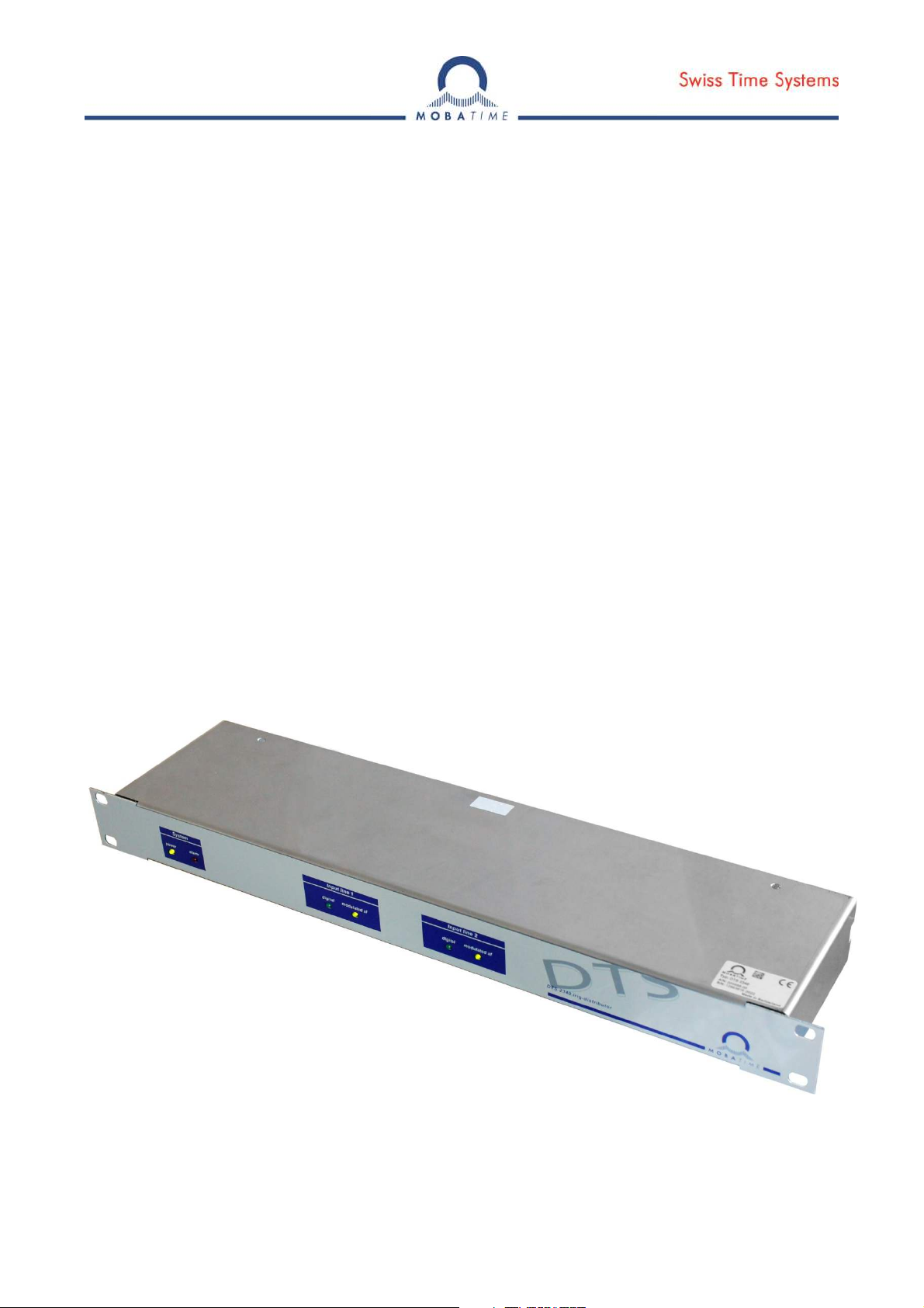
© MOBATIME 3 / 16 800860.04
Table of contents
1 Safety ..................................................................................................................................................... 4
1.1 Safety instructions............................................................................................................................... 4
1.2 Symbols and Signal Words used in this Instruction Manual.................................................................. 4
1.3 Intended Use ...................................................................................................................................... 4
1.4 Observe operating safety! ................................................................................................................... 4
1.5 Consider the installation site!............................................................................................................... 5
1.6 Please observe the electromagnetic compatibility!............................................................................... 5
2 Maintenance ........................................................................................................................................... 6
2.1 Troubleshooting: Repairs .................................................................................................................... 6
2.2 Cleaning ............................................................................................................................................. 6
2.3 Disposal.............................................................................................................................................. 6
3 General Information: Introduction ............................................................................................................ 7
3.1 Scope of Delivery................................................................................................................................ 7
3.2 Device Description in this Manual........................................................................................................ 7
3.3 Abbreviations...................................................................................................................................... 7
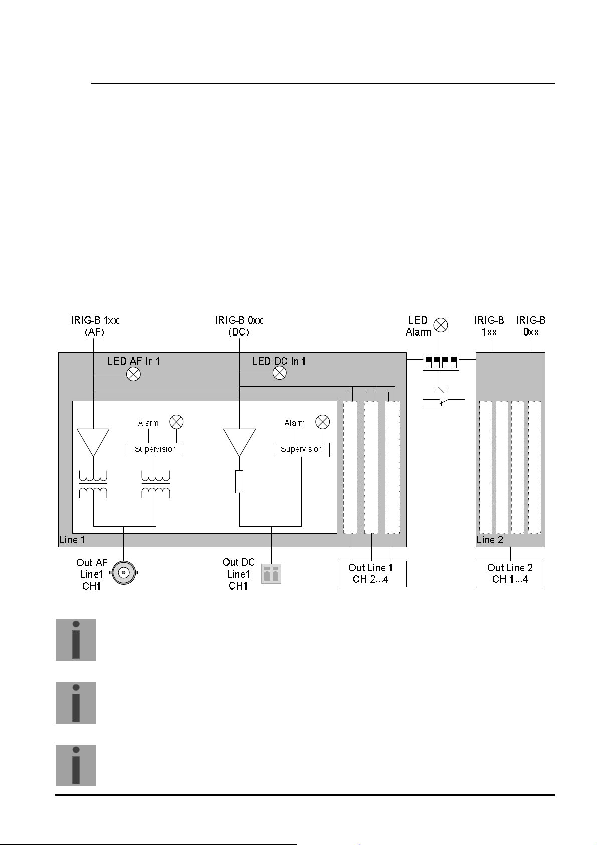
3.4 Description of Operation...................................................................................................................... 8
3.4.1 Monitoring ................................................................................................................................ 9
3.4.2 Alarms...................................................................................................................................... 9
3.4.3 Display ..................................................................................................................................... 9
4 Configuration and Display ..................................................................................................................... 10
4.1 Status Indicators: Front ..................................................................................................................... 10
4.2 Signal LEDs: Back ............................................................................................................................ 10
4.3 Configuration of the IRIG Distributor.................................................................................................. 10
5 Connections.......................................................................................................................................... 11
5.1 Power Supply.................................................................................................................................... 11
5.2 Input ................................................................................................................................................. 11
5.3 Output............................................................................................................................................... 11
5.4 Alarm Relay ...................................................................................................................................... 12
5.5 Connection between DTS 4135/4138 and IRIG Distributor ................................................................ 12
6 Technical Data...................................................................................................................................... 13
7 Dimensions of the IRIG Distributor ........................................................................................................ 14

© MOBATIME 4 / 16 800860.04
1 Safety
1.1 Safety instructions
Read this chapter and the entire instruction manual carefully and follow all instructions
listed. This is your assurance for dependable operations and a long life of the device.
Keep this instruction manual in a safe place to have it handy every time you need it.
1.2 Symbols and Signal Words used in this Instruction Manual
Danger!
Please observe this safety message to avoid electrical shock!
There is danger to life!
Warning!
Please observe this safety message to avoid bodily harm and injuries!
Caution!
Please observe this safety message to avoid damages to property and devices!
Notice!
Additional information for the use of the device.
1.3 Intended Use
The DTS 2340.irig-distributor is a signal distributor for IRIG-B 1xx Audio Frequency
(AF) and IRIG-B 0xx Digital (D) signals. The distributor contains two equal lines which
provide their Audio Frequency and Digital imput signal on four outputs each.
For additional functions, see the device descriptions in Chapter 3.4.
1.4 Observe operating safety!
Never open the housing of the device! This could cause an electric short or even a fire,
which would damage your device. Do not modify your device!
!
Caution!
!
!

© MOBATIME 5 / 16 800860.04
The device is not intended for use by persons (including children) with limited physical,
sensory, or mental capacities or a lack of experience and/or knowledge.
Keep packaging such as plastic films away from children. There is the risk of suffoca-
tion if misused.
1.5 Consider the installation site!
To avoid any operating problems, keep the device away from moisture and avoid dust,
heat, and direct sunlight. Do not use the device outdoors.
The device is designed for 19" racks and should only be operated installed in a 19"
cabinet.
By operating the device, the heat sinks attached to the sides get warm.
Make sure there is enough air circulation for the heat to dissipate.
Danger! Make sure
that you wait before using the device after any transport until the device has
reached the ambient air temperature. Great fluctuations in temperature or humidi-
ty may lead to moisture within the device caused by condensation, which can
cause a short.
1.6 Please observe the electromagnetic compatibility!
This device complies with the requirements of the EMC Directive 2004/108/EG and
96/48/EG
!
Caution!
!
Caution!

© MOBATIME 6 / 16 800860.04
2 Maintenance
2.1 Troubleshooting: Repairs
If you cannot rectify the problems, contact your supplier from whom you have pur-
chased the device.
Any repairs must be carried out at the manufacturer’s plant.
Disconnect the power supply immediately and contact your supplier, if …
liquid has entered your device
the device does not properly work and you cannot rectify this problem yourself.
2.2 Cleaning
Please make sure that the device remains clean especially in the area of the con-
nections, the control elements, and the display elements.
Clean your device with a damp cloth only.
Do not use solvents, caustic, or gaseous cleaning substances.
2.3 Disposal
Device
At the end of its lifecycle, do not dispose of your device in the regular household rub-
bish. Return your device to your supplier who will dispose of it correctly.
Packaging
Your device is packaged to protect it from damages during transport.
Packaging is made of materials that can be disposed of in an environmentally friendly
manner and properly recycled.

© MOBATIME 7 / 16 800860.04
3 General Information: Introduction
3.1 Scope of Delivery
Please check your delivery for completeness and notify your supplier within 14 days
upon receipt of the shipment, if it is incomplete.
The package you received contains:
DTS 2340.irig-distributor
1 pc mounting tool for spring terminals
Optionally available accessories
adapter BNC for screw-type terminal for connecting two-wire lines to the BNC
sockets of the AF outputs.
3.2 Device Description in this Manual
This manual refers to the DTS 2340.irig-distributor. In the following chapters, the
terms IRIG-Distributor or simply distributor will be used in order to increase the
readability.
3.3 Abbreviations
This manual uses the following abbreviations:
AF Audio Frequency amplitude modulated IRIG signal
D Digital IRIG signal without modulation

© MOBATIME 8 / 16 800860.04
3.4 Description of Operation
The DTS 2340.irig-distributor is a signal transmitter for IRIG-B 1xx (AF) and
IRIG-B 0xx (D) signals. The transmitter consists of two identical lines that operate
independently of one another.
Each line has an AF port (BNC connector and spring terminal) and a digital port (spring
terminal).
Each of these input signals is converted to four outlet signals in the IRIG distributor.
The AF signals are transmitted via BNC connectors, and the digital signals are made
available through spring terminals.
Line 1 and Line 2:
Input: IRIG-B 1xx (AF, modulated)
IRIG-B 0xx (digital, unmodulated)
Output: 4 x IRIG-B 1xx (AF, modulated)
4 x IRIG-B 0xx (digital, unmodulated)
50R
Channel 1
Channel 2
Channel 3
Channel 4
Channel 1
Channel 2
Channel 3
Channel 4
Important
:
The analog and the digital signal distribution can be used at the same
time.
Important
:
The digital inputs are only distributed to the digital outputs and the analog
inputs are only distributed to the analog outputs. This means, the digital
and the analog distribution is completely independent.
Important
:
The 2340.irig-distributor can also be used to distribute impulse signals.
For this application the digital in- and outputs are used.

© MOBATIME 9 / 16 800860.04
3.4.1 Monitoring
The IRIG distributor measures and monitors the peak of the signal level at each outlet.
Should one of the signals drop below a specified threshold, an alarm will be activated.
The threshold for a valid digital signal is fixed at 2.6V ± 20%. The threshold for monitoring AF
output signals can be adjusted using two DIP switches (see chapter 4.3).
3.4.2 Alarms
An alarm will be activated for each outlet whose signal level drops below the specified moni-
toring threshold.
At any given time, all activated alarms will be combined into one collective alarm. An alarm
LED on the front of the distributor indicates the status of the collective alarm. In the case of
an error, the alarm relay will be switched.
With the use of four DIP switches (see chapter 4.3), monitoring can be switched off for each
of the four inlets and their corresponding outlets. If an inlet is not in use, the corresponding
monitoring switch must be turned off to avoid a permanent error.
3.4.3 Display
An LED on the front of the distributor indicates the status of all input signals. An LED on the
back of the device shows the status of each outlet.
The brightness of the digital output LEDs hints at the load connected to the output and at the
resulting output voltage. The weaker the glow of the LED, the stronger the load of the output.

© MOBATIME 10 / 16 800860.04
4 Configuration and Display
4.1 Status Indicators: Front
Six LEDs on the front of the device indicate the status of the distributor.
LED
Status
Meaning
power
On
The distributor is receiving power.
Off
The distributor is not receiving power.
alarm
On
There is at least one active error.
Off
There are no active errors.
Input
line 1
digital
On
Signal is d
etected.
Off
No signal is present.
modulated
AF
On
Signal is detected.
Off
No signal is present.
Input
line 2
digital
On
Signal is detected.
Off
No signal is present.
modulated
AF
On
Signal is detected.
Off
No signal is present.
4.2 Signal LEDs: Back
An LED on the rear of the device indicates the status of each output signal.
Status
Meaning
Off
Outlet is inactive or is below the specified threshold.
On
Signal is detected.
4.3 Configuration of the IRIG Distributor
On the rear of the IRIG distributor, there are six DIP switches
for configuring the performance of the device.
The first two switches are for setting the monitoring threshold
for the AF output signals.
Switches 3–6 can be used to disable monitoring of each indi-
vidual input signal and its corresponding output.
Switch
Threshold
2
1
[Vpp]
OFF
OFF
1.
2
V ±
20%
OFF
ON
2
.
0
V ±
20%
ON
OFF
2.
8
V ±
20%
ON
ON
3
.
1
V ±
20%
Switch
Status
Meaning
3
ON/OFF
Switch monitoring on/off for AF signal, line 1
4
ON/OFF
Switch monitoring on
/off for AF signal, line 2
5
ON/OFF
Switch monitoring on/off for D signal, line 1
6
ON/OFF
Switch monitoring on/off for D signal, line 2
ON
1
2
3
4
5
6
Level Alarm Enable

© MOBATIME 11 / 16 800860.04
5 Connections
Line 1 and DC Power Supply:
Line 2 and Alarm Contact, DIP Switches for Configuring Alarms:
5.1 Power Supply
The power plug has the following pin assignment:
Terminal
Description
DC In+
Inlet for external DC power supply, 24
–
65V
DC In
-
Ground connection for external DC power
supply
In order to guarantee a safe operation concerning the EMC, the device can optionally
be connected to earth using the functional earth connector.
5.2 Input
Both inlets for a line are positioned together in an input field
for that line. Each one consists of a BNC connector for the
AF signal and a spring terminal for the AF and the digital
signals.
5.3 Output
Each of the two lines has four output fields. Each output
field carries the corresponding AF and digital signals.
connector functional earth

© MOBATIME 12 / 16 800860.04
5.4 Alarm Relay
The alarm relay contacts are configured as follows:
Terminal
Connection
Description
1
Alarm rela
y opener
Opens during alarm
2
Alarm relay closer
Closes during alarm
3
Alarm relay changer
Combined tapping
Capacities for the relay contacts are as follows:
30W (60 VDC or 1A) or
60VA (30 VAC or 1A)
5.5 Connection between DTS 4135/4138 and IRIG Distributor
Signal
output
Signal
typ
e
Max. cab
l
e
length
Output
connection
DTS 4135/4138
Input connection
DTS 2340
Impulse Digital, TTL 5 m RS422 + Linie 1 Input Digital +
GND Linie 1 Input Digital –
Digital, inverted, TTL 5 m RS422 - Linie 1 Input Digital +
GND Linie 1 Input Digital –
Digital, RS422
(differencial) 1000 m RS422 + Not allowed
RS422 - Not allowed
IRIG Digital, TTL 5 m RS422 + Linie 1 Input Digital +
GND Linie 1 Input Digital –
Digital, inverted, TTL 5 m RS422 - Linie 1 Input Digital +
GND Linie 1 Input Digital –
Digital, RS422
(differencial) 1000 m RS422 + Not allowed
RS422 - Not allowed
Analog, AM 1000 m IRIG 1xx
(BNC Stecker) Linie 1/2 Input IRIG AF
(BNC connector)
Analog, AM 1000 m IRIG 1xx
(BNC Stecker) Linie 1/2 Input AF +
Linie 1/2 Input AF -
DTS 4138.timeserver
DTS 413
5
.timeserver
8 x IRIG- or Impulse outputs 2 x 4 IRIG- or Impulse outputs

© MOBATIME 13 / 16 800860.04
6 Technical Data
Input Signals 2x IRIG-B 1xx (AF): BNC connector and spring terminal
2x IRIG-B 0xx (D): Spring terminal
Output Signals 4 output channels for each input signal
AF: BNC connector
D: Spring terminal
Output Impedance AF: 50Ω @ 1kHz
D: 50Ω
Power Supply 24...65VDC
Power Input < 15W
Operation 4 DIP switches for enabling alarms, one assigned to each of
the 4 inlets and their corresponding outlets. If an inlet is not
in use, the corresponding monitoring switch must be turned
off to avoid a permanent error.
2 DIP switches: Voltage level for the supervision of the AF
output signals
Display Power LED – Front (green)
Alarm LED – Front (red)
4x Signal-In LEDs – Front (green)
16x Signal-Out LEDs – Back (green)
Input gauge The input LEDs glow if at least the following input gauges fit:
AF: min. 0.9Vpp
max. 5Vpp
Digital: min. 2.3V
Input Impedance AF: 600 Ω
Digital: 600 Ω
Output gauge AF: same as input gauge, min. 2.3 Vpp
Digital: 5V (TTL)
Propagation delay AF: typically 1μs @ 1KHz
Digital: typically 100ns
Monitoring The voltage levels for the output signals are monitored with
the following alarm thresholds:
Alarm AF: 1.2Vpp ± 20% (SW2 OFF; SW1 OFF)
2.0Vpp ± 20% (SW2 OFF; SW1 ON)
2.8Vpp ± 20% (SW2 ON; SW1 OFF)
3.1Vpp ± 20% (SW2 ON; SW1 ON)
Alarm D: 1.9V ± 20%
Alarms Alarm relay (opener and closer)
30W (60VDC or 1A)
60VA (30VAC or 1A)
Housing 19” stand / 1 HU
Temperature -5...+50°C

© MOBATIME 14 / 16 800860.04
7 Dimensions of the IRIG Distributor
The IRIG distributor has the following dimensions in millimeters:

© MOBATIME 15 / 16 800860.04

© MOBATIME BE-800860.04
Table of contents
Other Mobatime Power Distribution Unit manuals