Flintec KAEX-4 User manual


Kabelanschlusskasten Typ KAEX Technisches Handbuch, Rev. 1.02 September 2016
Junction Box Type KAEX Technical Manual
Seite / Page 2 / 8
Inhaltsverzeichnis
Produkthaftung...................................................................................................................................................3
Sicherheitshinweise...........................................................................................................................................3
Allgemeines und technische Daten..................................................................................................................3
Mechanische Installation...................................................................................................................................4
Elektrische Anschlüsse .....................................................................................................................................4
Anschluss der Wägezellenkabel.......................................................................................................................4
Anschluss des Ausgangskabels.......................................................................................................................4
Eckenabgleich bei Waagen mit FLINTEC-Wägezellen....................................................................................5
Table of contents
RIGHTS AND LIABILITIES..................................................................................................................................6
Safety Instructions .............................................................................................................................................6
Introduction and technical Data........................................................................................................................6
Mechanical Installation ......................................................................................................................................6
Electrical Connections.......................................................................................................................................7
Load Cell Cable Connection..............................................................................................................................7
Output Cable Connection ..................................................................................................................................7
Corner Correction at Scales with Flintec Load Cells......................................................................................8
Kabelanschlusskasten Typ KAEX Technisches Handbuch, Rev. 1.02 September 2016
Junction Box Type KAEX Technical Manual
Seite / Page 3 / 8
PRODUKTHAFTUNG
Alle Rechte vorbehalten.
Kein Teil dieser Veröffentlichung darf ohne vorherige schriftliche Genehmigung durch die Flintec GmbH kopiert,
gespeichert oder in irgendeiner Form oder mit irgendwelchen Mitteln übertragen oder wieder-verwendet werden –sei es
mechanisch, fotokopiertechnisch oder jegliche andere Form der Vervielfältigung und Archivierung.
Im Hinblick auf den Gebrauch der enthaltenen Information ist sich die Flintec GmbH keinerlei Verstoßes gegen das
Patentrecht bewußt. Trotz größter Sorgfalt bei der Erstellung dieses Handbuchs übernimmt Flintec keinerlei
Verantwortung für Fehler oder Auslassungen in diesem Handbuch. Jegliche Haftungsansprüche für Schäden, die durch
Gebrauch der in diesem Handbuch enthaltenen Information entstehen können, werden ausgeschlossen.
Der Inhalt dieses Handbuchs wird als richtig und zuverlässig betrachtet. Sollten jedoch Fehler jeglicher Art gefunden
werden, dann ist die Flintec GmbH um jeden Hinweis dankbar. Flintec kann allerdings keinerlei Haftung für direkte oder
indirekte Schäden übernehmen, die durch den Gebrauch dieses Handbuchs entstehen können.
Die FLINTEC GmbH bewahrt sich das Recht, dieses Handbuch jederzeit ohne vorherige Ankündigung zu überarbeiten
und den Inhalt zu verändern.
Weder Flintec noch alle angeschlossenen Tochtergesellschaften können von dem Käufer dieses Produktes oder Dritten
haftbar gemacht werden für Schäden, Verluste, Kosten oder sonstige Ausgaben, die in Folge von Unfall, falscher
Anwendung und Missbrauch dieses Produktes oder unbefugter Modifikation, Reparatur oder Veränderung am Produkt
oder durch den Ausfall bei sachgemäßer Verwendung gemäß den Flintec Bedienungs- und Wartungsanleitungen
angefallen sind.
FLINTEC kann nicht haftbar gemacht werden für Schäden oder Probleme, die durch die Anwendung von Zubehör oder
anderen Verbrauchsgütern enstanden sind, die nicht als originale Flintec Produkt ausgewiesen sind.
Wichtig: Änderungen am Inhalt dieses Handbuchs ohne vorherige Ankündigung sind vorbehalten.
Copyright © 2007 der Flintec GmbH, 74909 Meckesheim, Bemannsbruch 9, Germany
SICHERHEITSHINWEISE
VORSICHT LESEN Sie diese Handbuch VOR dem Betrieb oder der Wartung des Gerätes. BEFOLGEN
Sie die Anweisungen sorgfältig. Bewahren Sie dieses Handbuch als Nachschlagewerk sicher auf. ERLAUBEN
SIE KEINER ungeschulten Person die Bedienung, Reinigung, Überprüfung, Reparatur oder Eingriff in dieses
Gerät. TRENNEN Sie das Gerät IMMER vom Spannungsnetz bevor Reinigungs- oder Wartungsmaßnahmen
ausgeführt werden. KONTAKTIEREN Sie FLINTEC für Information, Service und Ersatzteile.
WARNUNG ERLAUBEN SIE NUR BERECHTIGTEN PERSONEN DEN SERVICE AN DIESEM GERÄT.
LASSEN SIE SORGFALT WALTEN BEIM PRÜFEN, TESTEN UND EINSTELLEN, WENN DAS GERÄT
UNTER ELEKTRISCHER SPANNUNG STEHT. EINE MISSACHTUNG KANN ZU KÖRPERSCHÄDEN
FÜHREN.
WARNUNG FÜR DAUERHAFTEN SCHUTZ GEGEN ELEKTRISCHE GEFAHREN DARF DAS GERÄT
NUR AN EINEM SPANNUNGSVERSORGUNGSNETZ MIT FUNKTIONSFÄHIGER VERBINDUNG ZUR
SCHUTZERDE BETRIEBEN WERDEN. ENTFERNEN SIE NIEMALS DIE VERBINDUNG ZUM
SCHUTZKONTAKT/SCHUTZLEITER.
WARNUNG TRENNEN SIE ALLE VERBINDUNGEN ZUR SPANNUNGSVERSORGUNG BEVOR DIE
SICHERUNG GEWECHSELT WIRD ODER SONSTIGE SERVICEARBEITEN AUSGEFÜHRT WERDEN.
WARNUNG VOR DEM ANSCHLIESSEN/TRENNEN VON INTERNEN ELEKTRISCHEN
KOMPONENTEN ODER DEM VERBINDEN MIT ELEKTRISCHEN GERÄTEN TRENNEN SIE IMMER DIE
SPANNUNGSVERSORGUNG UND WARTEN SIE FÜR MINDESTENS 30 (DREISSIG) SEKUNDEN BEVOR
SIE DIESE MASSNAHMEN AUSFÜHREN. EIN NICHTBEACHTEN DIESER WARNUNG KANN ZU EINEM
GERÄTESCHADEN ODER ZUR ZERSTÖRUNG DES GERÄTES ODER ZU KÖRPERSCHÄDEN FÜHREN.
VORSICHT ERGREIFEN SIE ALLE VORSICHTSMASSNAHMEN FÜR DEN UMGANG MIT
ELEKTROSTATISCH EMPFINDLICHEN GERÄTEN.
ALLGEMEINES UND TECHNISCHE DATEN
Der lackierte Aluminium –Anschlusskasten ist für den Parallel-Anschluss von bis zu 4 Wägezellen vorbereitet.
Er ist in 2 Versionen lieferbar:
Typ
Anzahl Wägezellen
Abmessungen
Eingänge
Ausgang
Vers.
Kennzeichnung
KAEX-4
bis 4
80 x 250 x 52 mm
4x M16
1x M20
1
EEx ia IIC T6
2
EEx e IIC T6
Der Anschluss zum Anzeigegerät bzw. zur Auswerteelektronik erfolgt über ein abgeschirmtes 6-adriges
Signalkabel. Eine Eckenkorrektur erfolgt mit Widerständen.
Gehäusematerial:
Aluminium
Gehäuseschutzart:
IP66
Kabel-Anschluss:
Mit Schraubklemmen

Kabelanschlusskasten Typ KAEX Technisches Handbuch, Rev. 1.02 September 2016
Junction Box Type KAEX Technical Manual
Seite / Page 4 / 8
Eckenabgleich:
Mit austauschbaren Festwiderständen
MECHANISCHE INSTALLATION
Als Einbauort sollte ein möglichst trockener und vor Umwelteinflüssen geschützter Ort gewählt werden.
ELEKTRISCHE ANSCHLÜSSE
Abbildung 1: Abmessungen in [mm]
Die Anschlussreihenfolge der Wägezellen sollte mit den Ecken der Waage übereinstimmen, also
Ecke 1 = Wägezelle 1, Ecke 2 = Wägezelle 2, usw.
ANSCHLUSS DER WÄGEZELLENKABEL
Die Kabelverschraubung muß gelockert werden. Danach wird das Wägezellenkabel soweit in die
Verschraubung eingeführt, bis der Schrumpfschlauch vollständig in der Verschraubung verschwindet. Danach
können die Anschlussleitungen wie folgt aufgelegt und festgeklemmt werden:
Leitungsfarbe
Beschreibung
Klemmenbezeichnung
WZ1
WZ2
WZ3
WZ4
gelb
= Kabelschirm
1
2
23
24
rot
= Signal –(Ausgang –)
15
16
17
18
weiss
= Signal + (Ausgang +)
11
12
13
14
schwarz
= Speisung –/ Excitation –(Eingang –)
19
20
21
22
(ggfs. braun)*
= Rückführung –/ Sense –
grün
= Speisung + / Excitation + (Eingang +)
7
8
9
10
(ggfs. blau)*
= Rückführung + / Sense +
* bei Wägezellen mit 6-Leiter Anschluss
Wenn alle Leitungen angeklemmt sind, müssen die Kabelverschraubungen festgezogen werden. Bitte prüfen
Sie anschließend, ob Dichtigkeit und Zugentlastung vorhanden sind.
ANSCHLUSS DES AUSGANGSKABELS
Das Signalkabel (Verbindung zwischen dem Anschlusskasten und der nachgeschalteten Auswerteelektronik)
sollte ein 6 –adriges abgeschirmtes Kabel sein und so kurz wie möglich gehalten werden. Da Signalkabel je
nach Typ und Hersteller verschiedene Leitungsfarben haben, wählen Sie die Farben entsprechend selbst aus.
Leitungsfarbe, Beispiel
Beschreibung
Klemme Nr.
Äußeres Kabelgeflecht
= Kabelschirm
1
rosa
= Signal –(Ausgang –/ Output –)
15
weiß
= Signal + (Ausgang + / Output +)
11
grau
= Rückführung –/ Sense –
20
braun
= Speisung –/ Excitation –(Eingang –/ Input –)
19
gelb
= Rückführung + / Sense +
9
grün
= Speisung + / Excitation + (Eingang + / Input +))
10
Kabelanschlusskasten Typ KAEX Technisches Handbuch, Rev. 1.02 September 2016
Junction Box Type KAEX Technical Manual
Seite / Page 5 / 8
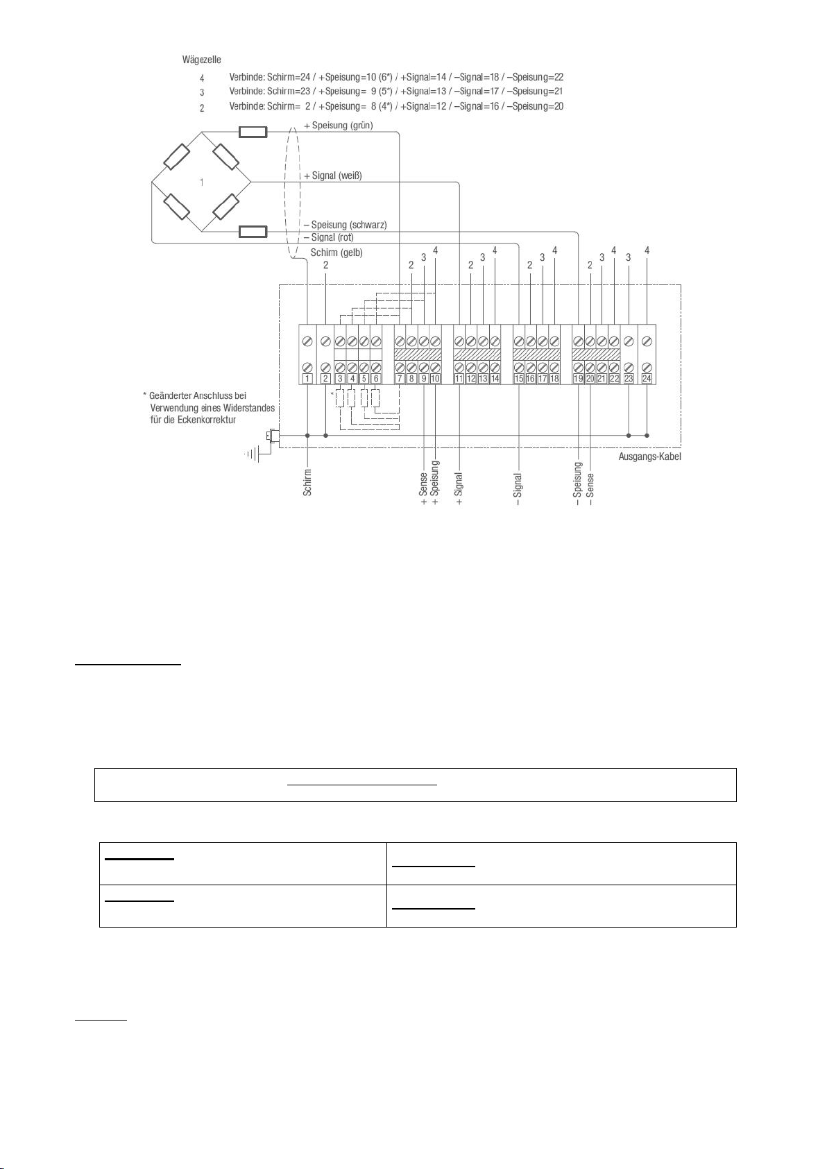
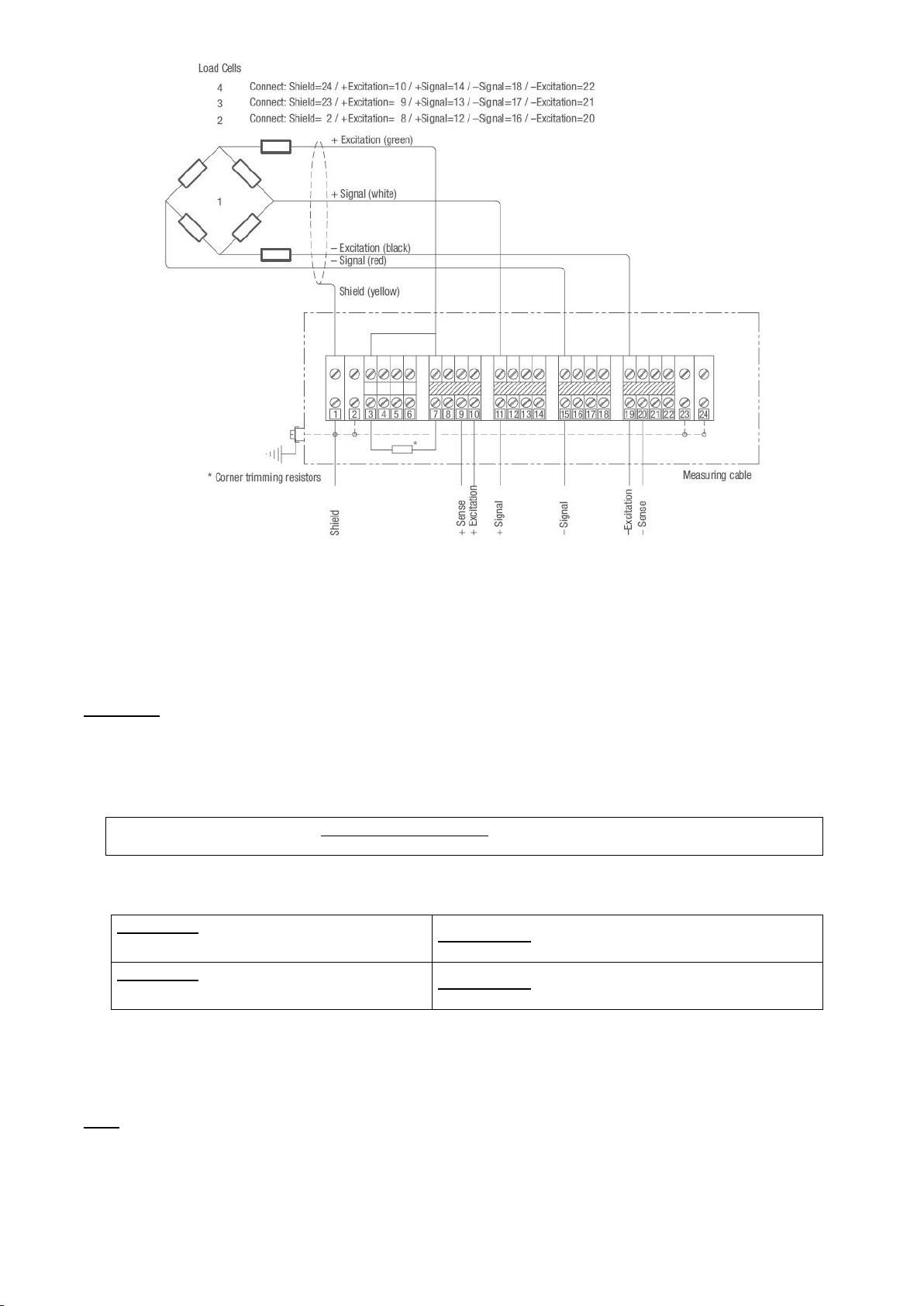
Abbildung 2: Kabelanschluss
ECKENABGLEICH BEI WAAGEN MIT FLINTEC-WÄGEZELLEN
Flintec-Wägezellen werden mit relativ engen Toleranzen gebaut, so daß in den meisten Fällen kein zusätz-
licher Eckenabgleich erforderlich ist. Die besten Voraussetzungen sind gegeben, wenn Wägezellen aus der
gleichen Klasse verwendet werden (Kennzeichnung erfolgt durch die Buchstaben A bis I auf der Verpackung
neben dem Typenschild). Hinweis: Eckenfehler können auch mechanische Ursachen haben, z.B. Neigung der
Wägezellen-Montagefläche.
Vorgehensweise:
1. Ermittlung des Anzeigewertes je Ecke. Möglichst mit erhöhter Auflösung des Anzeigegerätes (z.B. Faktor
10 oder höher) oder, wenn dies nicht möglich ist, durch Ausmessen des digitalen Ziffernsprunges der
Gewichtsanzeige mit entsprechenden Prüfgewichten.
2. Die Ecke mit dem niedrigsten Anzeigewert ist der Ausgangspunkt für die nun anschließende Korrektur.
Dementsprechend wird die Differenz der anderen Ecken in Bezug auf diese " Basisecke" errechnet.
3. Berechnung des Korrekturwiderstandes wie folgt:
Korrekturwiderstand in [] =
Abweichung in [kg]
X Eingangswiderstand der Wägezelle in [] *
Prüflast in [kg]
* Eingangswiderstand 1100 für:
BK2, SB4, SB5, SB6, SB14, SLB, ZLB, UB1, UB5, UB6, PB, RC3
Eingangswiderstand 400 für:
RC1, SB2
Beispiel 1: 1100 -Wägezellen
Eckenfehler 0,1 kg bei Prüflast 500 kg
0,1 kg
x
1100
=
0,22
500 kg
Beispiel 2: 400 -Wägezellen
Eckenfehler 10 kg bei Prüflast 5000 kg
10 kg
x
400
=
0,8
5000 kg
4. Einbau des Korrekturwiderstandes im Kabelkasten in die Speisung der entsprechenden Wägezelle.
z.B. für Wägezelle 1 wird die +Speisung von Klemme 7 nach Klemme 3 geändert und anschließend der
Korrekturwiderstand zwischen Klemme 3 und Klemme 7 eingefügt.
5. Ecken nochmals überprüfen. Gegebenenfalls das beschriebene Vorgehen wiederholen.
Hinweis: 50 ppm Widerstände für den Eckenabgleich sind als Satz mit 14 Werten von 0,22 bis 4,7
(jeweils 10 Stück) unter der Artikel -Nr. 5200-030 lieferbar.
Anschließend die Deckeldichtung auf Schmutz überprüfen und den Deckel mit dem Anschlusskasten gleich-
mäßig fest verschrauben.
Kabelanschlusskasten Typ KAEX Technisches Handbuch, Rev. 1.02 September 2016
Junction Box Type KAEX Technical Manual
Seite / Page 6 / 8
RIGHTS AND LIABILITIES
All rights reserved.
No part of this publication may be reproduced, stored in a retrieval system, or transmitted in any form or by any means,
mechanical, photocopying, recording, or otherwise, without the prior written permission of Flintec GmbH
No patent liability is assumed with respect to the use of the information contained herein. While every precaution has been
taken in the preparation of this book, FLINTEC assumes no responsibility for errors or omissions. Neither is any liability
assumed for damages resulting from the use of the information contained herein.
The information herein is believed to be both accurate and reliable. FLINTEC, however, would be obliged to be informed if
any errors occur. FLINTEC cannot accept any liability for direct or indirect damages resulting from the use of this manual.
FLINTEC reserves the right to revise this manual and alter its content without notification at any time.
Neither FLINTEC nor its affiliates shall be liable to the purchaser of this product or third parties for damages, losses, costs,
or expenses incurred by purchaser or third parties as a result of: accident, misuse, or abuse of this product or
unauthorized modifications, repairs, or alterations to this product, or failure to strictly comply with FLINTEC operating and
maintenance instructions.
FLINTEC shall not be liable against any damages or problems arising from the use of any options or any consumable
products other than those designated as Original FLINTEC Products.
NOTICE: The contents of this manual are subject to change without notice.
Copyright © 2007 by Flintec GmbH, 74909 Meckesheim, Bemannsbruch 9, Germany
SAFETY INSTRUCTIONS
CAUTION READ this manual BEFORE operating or servicing this equipment. FOLLOW these
instructions carefully. SAVE this manual for future reference. DO NOT allow untrained personnel to
operate, clean, inspect, maintain, service, or tamper with this equipment. ALWAYS DISCONNECT this
equipment from the power source before cleaning or performing maintenance. CALL FLINTEC
ENGINEERING for parts, information, and service.
WARNING ONLY PERMIT QUALIFIED PERSONNEL TO SERVICE THIS EQUIPMENT.
EXERCISE CARE WHEN MAKING CHECKS, TESTS AND ADJUSTMENTS THAT MUST BE MADE
WITH POWER ON. FAILING TO OBSERVE THESE PRECAUTIONS CAN RESULT IN BODILY HARM.
WARNING FOR CONTINUED PROTECTION AGAINST SHOCK HAZARD CONNECT TO
PROPERLY GROUNDED OUTLET ONLY. DO NOT REMOVE THE GROUND PRONG.
WARNING DISCONNECT ALL POWER TO THIS UNIT BEFORE REMOVING THE FUSE OR
SERVICING.
WARNING BEFORE CONNECTING/DISCONNECTING ANY INTERNAL ELECTRONIC
COMPONENTS OR INTERCONNECTING WIRING BETWEEN ELECTRONIC EQUIPMENT ALWAYS
REMOVE POWER AND WAIT AT LEAST THIRTY (30) SECONDS BEFORE ANY CONNECTIONS OR
DISCONNECTIONS ARE MADE. FAILURE TO OBSERVE THESE PRECAUTIONS COULD RESULT
IN DAMAGE TO OR DESTRUCTION OF THE EQUIPMENT OR BODILY HARM.
CAUTION OBSERVE PRECAUTIONS FOR HANDLING ELECTROSTATIC SENSITIVE
DEVICES.
INTRODUCTION AND TECHNICAL DATA
The painted Aluminium junction box is designed for the parallel connection of 4 load cells. 2 versions are
available.
Type
No. of load cells
Housing size
Inputs
Output
Version
Designation
KAEX-4
up to 4
80 x 250 x 52 mm
4x M16
1x M20
1
EEx ia IIC T6
2
EEx e IIC T6
The junction box type KAEX can be connected to the instrumentation with a shielded 6-wire signal cable.
The corner correction is done with resistors.
Housing material:
Aluminium
Protection class:
IP66
Cable connection:
With screw terminals
Corner correction:
By exchangeable resistors
MECHANICAL INSTALLATION
Look for a mounting location which is more or less dry and protected from environmental stress.
Kabelanschlusskasten Typ KAEX Technisches Handbuch, Rev. 1.02 September 2016
Junction Box Type KAEX Technical Manual
Seite / Page 7 / 8
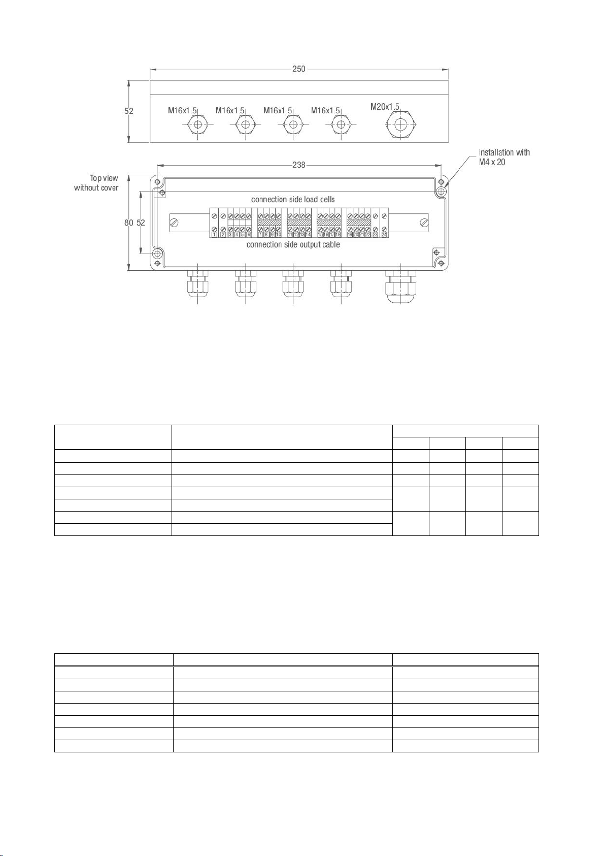
ELECTRICAL CONNECTIONS
Figure 1: Dimensions in [mm]
The connection sequence of the load cells should correspond to the corners of the scale, i.e
Corner 1 = Load cell 1, Corner 2 = Load cell 2, etc.
LOAD CELL CABLE CONNECTION
First the cable gland must be loosened. Then you have to feed the load cell cable through the cable gland
unless the shrink tube is fully disappeared in the box. Afterwards you can connect the cables to the screw
terminals as indicated below:
Cable coulour
Description
Terminal no.
LC1
LC2
LC3
LC4
yellow
= Cable shield
1
2
23
24
red
= Signal –(Output –)
15
16
17
18
white
= Signal + (Output +)
11
12
13
14
black
= Excitation –(Input –)
19
20
21
22
(if applicable, brown)*
= Sense –
green
= Excitation + (Input +)
7
8
9
10
(if applicable, blue)*
= Sense +
* if load cell is equiped with 6-wire conductor cable
After all conductors have been screwd to the terminals, the cable glands must be tightened. Please verify that
all cable glands are tight and the cable is fully stress relieved.
OUTPUT CABLE CONNECTION
The signal cable (connection between junction box and the following electronics) should be a 6 –wire
shielded cable and has to be kept as short as possible. Depending on type and manufacturer signal cables
may have different colours. Therefore make your own choice.
Cable colour, example
Description
Terminal no.
outer cable screen
= Shield
1
pink
= Signal –(Output –)
15
white
= Signal + (Output +)
11
grey
= Sense –
20
brown
= Excitation –(Input –)
19
yellow
= Sense +
9
green
= Excitation + (Input +)
10
Kabelanschlusskasten Typ KAEX Technisches Handbuch, Rev. 1.02 September 2016
Junction Box Type KAEX Technical Manual
Seite / Page 8 / 8
Figure 2: Wiring
CORNER CORRECTION AT SCALES WITH FLINTEC LOAD CELLS
Flintec load cells are manufactured with rather tight tolerances, so in most cases an additional corner
correction is not required. The best conditions are achieved if you use load cells of the same class
(Designation is done with capital letters A to I on the load cell package besides the type label).
Hint: Corner errors can have a mechanical background, e.g. sloped mounting surface of the load cell.
Procedure:
6. Get the display value for each corner. Use the highest possible display resolution (e.g. factor 10 or higher)
or, if this is not possible, measure the the digital weight increment using corresponding weights.
7. The corner with the lowest display value is the starting point for the corner correction. The differences of
the other corners are calculated with reference to this “basic corner”.
8. Calculate the correction resistance as follows:
Correction resistance [] =
Deviation in [kg]
X Input resistance of the load cell [] *
Test load in [kg]
* 1100 input resistance for:
BK2, SB4, SB5, SB6, SB14, SLB, ZLB, UB1, UB5, UB6, PB, RC3
400 input resistance for:
RC1, SB2
Example 1: 1100 load cell
0.1 kg corner error with 500 kg test load
0.1 kg
x
1100
=
0.22
500 kg
Example 2: 400 load cell
10 kg corner error with 5000 kg test load
10 kg
x
400
=
0.8
5000 kg
9. Install the correction resistor into the junction box for the corresponding load cell excitation, e.g. for load
cell no. 1 the +excitation wire has to be changed from terminal no. 7 to terminal no. 3 and afterwards the
correction resistor has to be inserted between terminal no. 3 and terminal no. 7.
10. Check the corners again. If required repeat the procedure.
Hint: 50 ppm resistors for corner correction are available as a set of 14 values from 0.22 to 4.7 (10 pcs.
for each value; article no. 5200-030).
Check the cover sealing and install the cover of the box.
Table of contents
Languages:
Other Flintec Power Distribution Unit manuals


