Mobile Mark TMA-24A-302CT User manual

1
Mission
CriticalWi-Fi
HIGH
PERFORMANCE
TACTICALMESHANTENNA(HP-TMA)
QUICK INSTALL GUIDE
Shown
with
optional NATO mount
adapter
Congratulations on your
purchase
of
the MMIHigh
P
er
f
ormanc
e
Tactical
M
e
s
h
An
t
e
nna
!
You are
j
u
s
t
minutes away
from
enjoying the benefits
of a farther r
eaching
,
clearer wireless signal
.
Pr
oduct
s
covered
by
this
Guide
TMA-24A-302CT
-
2
.
4GHz
HP-TMA
(33dBm), RHCP
Omnidirectional
TMA-5XA-302CT
-
5GHz HP-TMA
(33dBm), VP
Omnidirectional
TMA-5XA-304VT
-
5GHz HP-TMA
(35dBm), VP
Omnidirectional
TMA-5XSA-307VT
-
5GHz HP-TMA
(37dBm), VP 180 Degree
Sec
t
or
TMA-44A-305VT
-
5GHz HP-TMA
(35dBm), VP
Omnidirectional

2
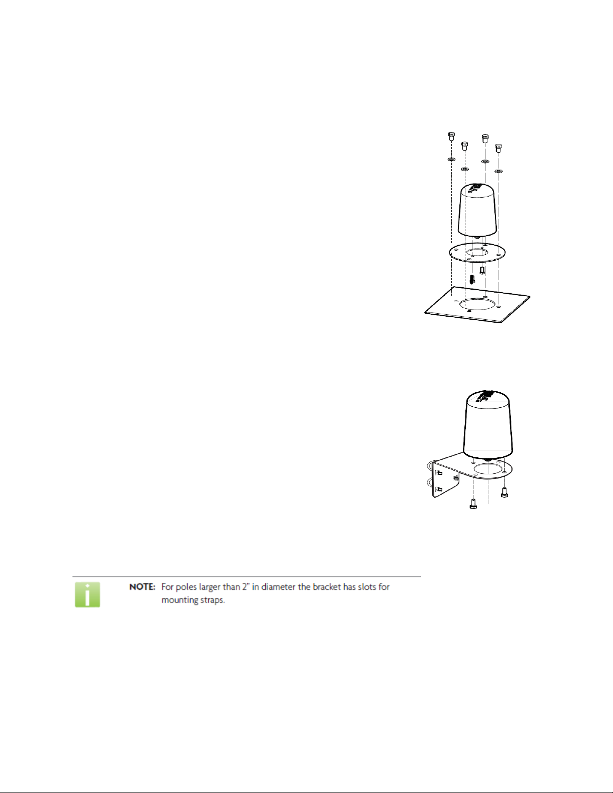
High Performance Tactical Mesh Antenna (HP-TMA)
WARRANTY
Mobile Mark, Inc. (Seller) warrants to Buyer that the products for a period of two years from the date of shipment will be free from defects
of material and workmanship, and will be in accordance with specifications referred to herein. Seller’s sole obligation under these
warranties will be limited to either, at Seller’s option and expense, repairing, or furnishing a replacement F.O.B. First point of shipment for
the products or parts thereof which Seller reasonably determines do not conform with these warranties, and Buyer’s exclusive remedy for
breach of any of such warranties will be enforcement of such obligations of Seller. THE FOREGOING WARRANTIES ARE EXCLUSIVE AND IN
LIEU OF ALL OTHER WARRANTIES OF MERCHANTABILITY, FITNESS FOR PURPOSE AND OF ANY OTHER TYPE, WHETHER EXPRESS OF IMPLIED.
IN NO EVENT SHALL SELLER BE LIABLE FO R CONSEQUENTIAL DAMAGES, nor shall Seller’s liability on any claims for damages arising out of or
connected with the sales contract for the manufacture, sale, delivery or use of the products exceed the purchase price of the products. Any
action for breach of warranty must be commenced within one year after the cause of action accrues.
1140 W. Thorndale Ave. ˑItasca, IL 60143, USA ˑwww.mobilemark.com
Toll free: 1-800-648-2800 (US & Canada) ˑPhone 1-847-671-6690 ˑFax 1-847-250-5120
Moving Wireless Forward™
This product may be covered by one or more U.S. and foreign patents.
Patents: 7,783,270, 7,379,717, 6,606,075, 6,373,448, other patents pending
Document Conventions
The following graphical alerts are used in this document to indicate notable situations:

3
QUICK INSTALL GUIDE
Product ships with:
• HP-TMA
• Quick Install Guide
• Smart Power Over Coax (SPOC) Injector
• Power cable for SPOC
Additional Items required:
• 802.11 a or b/g radio
• N-Male to Radio Antenna Port, Coax cable (See your radio manufacturer’s set-up guide
for more information on the required connector for your Radio) to connect your radio
to the SPOC
• N-Male to N-Male, Coax cable to connect the SPOC to the HP-TMA
Required Tools:
• See the section, Mounting the HP-TMA, for necessary tools
Mounting the HP-TMA
The HP-TMA does not require a ground plane and can be mounted on any surface. We
suggest the following guidelines be followed for installation for maximum performance.
1. The HP-TMA must be mounted vertically with the logo facing upward. It should not be
mounted inverted or on an angle, (Figure 1).
2. There should be no obstructions on the same horizontal plane as the HP-TMA within a 12” (30.48cm) radius.
3. The HP-TMA should be mounted on a horizontal plane above any large metal objects that could act as obstructions, such as a
turret, passenger compartment or door.

4
Antenna Deployment
The type of radiation pattern produced by the HP-TMA varies for the different models.
Figure 2 shows where the HP-TMA should be mounted in the desired coverage area.
OMNI
SECT
OR
Mounting Direction for the HP-TMA Sector Antenna
The HP-TMA Sector, TMA-5XSA-308T, is a directional antenna. You will need to be aware
of the direction it is pointing when deployed. The antenna signal radiates from the front
of the antenna. The back of the HP-TMA sector indicated by the word “BACK” near the
bottom edge of the antenna, Figure 3

5
QUICK INSTALL GUIDE
Mounting the HP-TMA
(Optional) NATO Mount (HDW-TMA-45NATO) Figure 4
The Tactical Mesh Antenna (HP-TMA) can be mounted directly
to a vehicle using a standard 4.5” NATO mount hole pattern.
1. Use the two 1/4-20 by 1/2” screws to connect the NATO
mounting plate to the HP-TMA
2. Use the four 3/8-16 by 1” bolts to connect the NATO
mounting plate to the HP-TMA’s intended mounting
location or other hardware as required.
Required Tools
• 1/4” Wench for bolts to connect mount to the HP-TMA
• 1/4” Wench for bolts to connect mount to the vehicle
Figure 4
(Optional) Universal Mounting Bracket (HDW-TMA-UMB) Figure 5
The Tactical Mesh Antenna (HP-TMA) can be mounted to a
pole using the Universal mounting bracket.
1. Use the two 1/4-20 by 1/2” screws to connect the Universal
Mounting Bracket to the HP-TMA.
2. Use the two 2” U-Bolts to attach the mounting bracket to
pole with a diameter of 1” to 2”.
Figure 5
Note: See page 13 for Mounting Template
Required Tools
• 1/4” Wench for bolts to connect mount to the HP-TMA
• 1/4” Wench for bolts to connect mount to the vehicle

6
Coax CABLE Information
Cable Requirements
The HP-TMA and SPOC injector requires a Coax cable with an Impedance
of 50 Ohm and N-Male Connectors. Check with your radio manufacturer’s documentation
for the coax cable and connector requirements for your radio.
Connecting Coax CABLE
1. Connect the coax from the appropriate antenna port of your radio to the side of the
SPOC labeled INPUT, Figure 7, 1. (Radios with multiple antennas often have a primary
antenna port. The HP-TMA should be connected to this primary port. See your radio
manufacturer’s set-up guide for more information) The SPOC has an N-Male connector,
(See your radio’s manufacturer set-up guide for more information on the required
connector for your Radio).
2. Connect an N-Male to N-male coax cable between the side of the SPOC labeled
OUTPUT,2and the HP-TMA, 3.
3. If desired you may add an optional Lightning Arrestor (ACC-TW-LP-005N) or Gas Tube Surge Arrestor (ACC-GT-NFF-AL)
between the SPOC and your Radio.

7
QUICK INSTALL GUIDE
SMART POC
The SMART (Serially Manageable And Reporting TMA) SPOC Injector is intended to
work with the various HP-TMA variations to allow for ease of installation and a simple
method of determining if the system is operational.
Powering the SMART POC
1. Connect the direct DC (M12 connector) cable to the PWR port of the SPOC injector,
Figure 7 1(next page).
2. Connect the power cable pigtail, to your power source as specified:
–– Blue: +VDC, Figure 8 2
–– Black: Ground, Figure 8 3
–– Brown: Disconnected, Figure 8 4

8
Once the SPOC injector has been connected to the power source and all other cables are
connected, power can now be applied.
Other Power Connection Options
• PWR-120V - 120V Power Supply for SPOC Injector
• PWR-POE - 2’ cable with M12 to RJ45 coupler for connecting SPOC injector to POE
source (Additional RJ45 cable and non-802.3af POE injector required)

9
QUICK INSTALL GUIDE
SMART SPOC LED Indicator
The SMART SPOC injector has a single multi color LED indicator, Figure 9, for determining operational status of the HP-TMA.
Power Up LED Functionality
• Red/Amber, flashing: During initial power up you will see Red/Amber flashing as the system confirms the presence of the HP-
TMA.
• Blue or Purple, solid: After discovering the HP-TMA, you will see one of the following
colors for 10 seconds, indicating the HP-TMA’s frequency.
–– Blue 2.4GHz
–– Purple 5.8GHz
Normal Operation LED Functionality
• Green, solid: The SPOC is properly communicating with the HP-TMA.
• Green, flashing: Indicates that TX traffic is being detected by the HP-TMA

10
Error Code LED Functionality
• Red/Amber, flashing constantly: SPOC is powered but has no HP-TMA attached or is not communicating with the HP-TMA.
–– Probable Cause:
−−HP-TMA has been removed or damaged.
−−Disconnected or bad coax.
–– Corrective Action:
−−Check for damage to the HP-TMA.
−−Check coax for damage or loose connection.
• Red/Blue flashing: Low input power
–– Probable Cause:
−− Low radio TX output power or too much signal loss between radio port and HP-TMA.
–– Corrective Action:
−−Check coax for damage or loose connection.
−− Adjust radio TX output power to suggested radio settings
−− Reduce the coax length between the HP-TMA and the radio
−− Replace with a lower loss coax between the HP-TMA and the radio
–– Red flashing: Low HP-TMA TX output power
–– Possible Cause:
−−HP-TMA failure
–– Corrective Action:
−−Contact Technical Support
Check troubleshooting section, at the end of this document, for additional corrective action suggestions.

11
QUICK INSTALL GUIDE
Optimizing your Radio
The HP-TMA operates best when the input power to the HP-TMA, from the radio, is
between +10dBm to +20dBm. Radio power may need to be adjusted for optimal performance.
Be sure to factor the dB loss for the SPOC and coax. The SPOC has approximately
1dB of loss.
Specifications for Cables Available from MMI
Cable
Frequency
ATTENUATION
dB/100FT
ATTENUATION
Db/100m
POWER
HANDLING (Kw)
LL-195
2500
17
N/A
0.09
5800
28.3
93.10
.06
LMR®-400
2500
6.80
22.31
0.33
5800
10.80
35.50
0.21
LMR® is a registered trademark of Times Microwave Systems.

12
TROUBLESHOOTING
If you make any changes to the system or notice any abnormal behavior we
suggest you power cycle the radio and equipment.
• Make sure the cables are properly connected and that there is power to
the TMA and your radio.
• Sometimes, radios with multiple antennas have primary and secondary
antenna ports. Be sure to connect the signal booster to the primary
antenna port of the radio as many secondary ports are receive only, or
do not transmit at the same power level as the primary antenna port. If
your radio has more than one antenna port, try connecting to a different
port and/or, if available, change the administration settings disable the
secondary antenna port. (See your radio’s documentation).
• Dual band radios have separate antennas for each band. Be sure you are
connecting the TMA’s coax cable to the appropriate antenna port.
• Ensure the TMA is properly positioned. Omni antennas should be centered
in the desired coverage area. Sector Antennas should be positioned with
the “BACK” indicator away from the desired coverage
area. For optimal performance antennas should have 2 feet (.6 meters)
of clearance with no obstructions.
•Circular Polarized signal is superior for penetrating
wood, concrete, and stucco, but all wireless signals can be disrupted by
certain obstructions, including large metal objects, or strong magnetic
fields. Try orienting the antenna where line-of-sight access to the desired
coverage area is available.
After checking the above items, if your MMI product still does
not seem to be functioning properly, please contact Technical Support at:
NOTE: The HP-TMA is not FCC Certified and is available for use by The United States
Military or for export only
Results may vary depending on building layout, type of construction and other environmental
factors including Wi-Fi traffic, Microwave Ovens, Cordless Phones, etc.
1140 W. Thorndale Ave. ˑItasca, IL 60143, USA ˑwww.mobilemark.com
Toll free: 1-800-648-2800 (US & Canada) ˑPhone 1-847-671-6690 ˑ
Fax 1-847-250-5120
Moving Wireless Forward™

2.75
(69.9mm)
1
4
" THRU
(6.4mm)
2.25
(57.2mm)
Standard Mount
4.50 B.C.
(114.3mm)
1
2
" THRU
(12.7mm)
NATO Mount
TMA Mounting Template
Make sure this area is
clear for vent holes
13
This manual suits for next models
4
Table of contents
Popular Antenna manuals by other brands

Sirio Antenne
Sirio Antenne Starduster M-400 quick start guide

Somogyi Elektronic
Somogyi Elektronic home FZ47 instruction manual

DIGITIZE
DIGITIZE Dipole-Lo manual

Siemens
Siemens SIMATIC NET ANT896-4MA operating instructions

Radio Shack
Radio Shack 15-1838 owner's manual

Chameleon Antenna
Chameleon Antenna CHA MPAS 2.0 Operator's manual