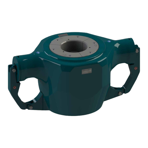
Mobility 2BB-EVO FP Series User manual

Sollevatori per disabile
Istruzioni originali
Wheelchair lift
Original instruction translation
M
MA
AN
NU
UA
AL
LE
E
D
DI
I
I
IN
NS
ST
TA
AL
LL
LA
AZ
ZI
IO
ON
NE
E
E
E
S
SE
ER
RV
VI
IC
CE
E
F
FI
IT
TT
TI
IN
NG
G
A
AN
ND
D
S
SE
ER
RV
VI
IC
CE
E
H
HA
AN
ND
DB
BO
OO
OK
K
i
i-
-C
Cl
la
as
ss
s
M
Mo
od
de
el
ll
li
i
M
Mo
od
de
el
ls
s
2
2B
BB
B
E
EV
VO
O
F
FP
P
2
2B
BB
B
E
EV
VO
O
P
P
2
2B
BB
B
E
EV
VO
O
S
SP
P

Pag. 2/ 64
i-class
Manuale di Installazione e Service
REV
01
27/02/2018
Fitting and Service Handbook
Mobility Networks
12 Estuary View Business Park, Whitstable, Kent, CT5 3SE, UK
Tel: +44 (0)1227 505022 Fax: +44 (0)1227 505023 www.mobilitynetworksgroup.com
Mobility Networks is a trading name of Mobility Networks (Holdings) Ltd. Registered in England & Wales number 08295602
i
i-
-C
Cl
la
as
ss
s
SOLLEVATORE DI SEDIE A ROTELLE
M
MA
AN
NU
UA
AL
LE
E
D
DI
I
I
IN
NS
ST
TA
AL
LL
LA
AZ
ZI
IO
ON
NE
E
E
E
S
SE
ER
RV
VI
IC
CE
E
Edizione 01
Nessuna parte di questo manuale può essere
riprodotta, memorizzata in un sistema di
archiviazione o trasmessa a terzi in qualsiasi
forma o con qualsiasi mezzo, senza che
Mobility Networks Holdings Ltd. abbia
rilasciato preventiva autorizzazione scritta.
Mobility Networks Holdings Ltd.si riserva il
diritto di apportare, in qualsiasi momento e
senza preavviso, modifiche e miglioramenti ai
prodotti per incrementarne la qualità, senza
che tali modifiche siano riportate nella
presente pubblicazione.
BREVETTO ITALIANO E INTERNA_
ZIONALE IN CORSO DI REGISTRAZIONE
This document is a translation of the
manufacturer’s original Italian instructions. If
further assistance is required, please refer to
the original document or forward a request to
Mobility Networks Holdings Ltd. This
handbook cannot be reproduce, stored by a
filing system or transmitted to third parties, in
whole or in part, in whatsoever form or
medium, whitout Mobility Networks
Holdings Ltd. prior written permission.
Mobility Networks Holdings Ltd. reserve
the right to carry out products changes and
improvements in order to enhance their
quality, at any time and without notice, even il
such modifications will not he reparted in this
pubblication.
ITALIAN AND FOREIGN PATENT
PENDING
EDIZIONE
DATA
MODIFICA
01
27/02/2018
UP GRADE WIRING ELECTRICAL AND HYDRAULIC

Manuale di Installazione e Service
i-class
Pag. 3 / 64
Fitting and Service Handbook
27/02/2018
REV
01
Mobility Networks
12 Estuary View Business Park, Whitstable, Kent, CT5 3SE, UK
Tel: +44 (0)1227 505022 Fax: +44 (0)1227 505023 www.mobilitynetworksgroup.com
Mobility Networks is a trading name of Mobility Networks (Holdings) Ltd. Registered in England & Wales number 08295602
Sommario
1. PREMESSA ................................................................... 6
1.1. Classificazione e considerazioni generali ................ 6
1.2. Compiti dell’allestitore / service ............................. 6
1.3. Documentazione a corredo..................................... 6
1.4. Garanzia .................................................................. 7
2. INDICAZIONI GENERALI................................................ 8
2.1. Descrizione tecnica ................................................. 8
2.2. Versioni e allestimenti............................................. 9
2.3. Specifiche tecniche.................................................. 9
2.4. Ingombri................................................................ 10
2.5. Dispositivi di Sicurezza .......................................... 12
2.6. Adesivi / Stickers ................................................... 13
3. OPERAZIONI PRELIMINARI......................................... 15
3.1. Trasporti e movimentazione ................................. 15
3.2. Specifiche dell’imballo .......................................... 15
4. VERIFICA DI STABILITÀ ............................................... 16
5. POSIZIONAMENTO E FISSAGGIO DEL SOLLEVATORE. 18
6. COLLEGAMENTI ELETTRICI......................................... 21
6.1. Alimentazione ....................................................... 21
7. IMPIANTO IDRAULICO ............................................... 23
7.1. Centralina elettroidraulica .................................... 23
7.2. Presa di pressione ................................................. 24
8. VERIFICA DELLA PRIMA MESSA IN SERVIZIO ............. 25
8.1. Targhette e stampa di identificazione /
Identification tag ................................................................ 26
8.2. Documentazione a corredo / Equipment
documentation................................................................... 27
8.3. Adesivi e avvisi di sicurezza / Safety stickers......... 28
8.4. Comandi / Controls ............................................... 29
8.5. Struttura e montaggio / Structure and assembly.. 30
8.6. Impianto idraulico / Hydraulic system .................. 31
8.7. Funzionalità del sollevatore / Lift function ........... 32
8.8. Impianto elettrico / Electrical wiring..................... 33
8.9. Dispositivi di sicurezza / Safety devices ................ 34
8.10. Prove di carico / Loading test ........................... 35
9. ISPEZIONI ORDINARIE ................................................ 36
9.1. Verifica della funzionalità del sollevatore / Lift
function check .................................................................... 37
9.2. Verifica del serraggio delle viti di fissaggio /
Tightening of fixing screws check....................................... 38
9.3. Verifica dei perni e delle boccole / Pins and
bushings ............................................................................. 39
9.4. Verifica delle connessioni elettriche / Electrical
connections check .............................................................. 40
9.5. Verifica delle connessioni idrauliche / Hydraulic
connections check .............................................................. 41
9.6. Verifica del livello dell’olio nel serbatoio / Tank oil
level check.......................................................................... 42
9.7. Verifica strutturale / Structural check................... 43
9.8. Verifica delle regolazioni / Regulation check ........ 44
9.9. Verifica targhette e adesivi / Plate and stickers
check 45
9.10. Verifica lubrificazione pedana ……………………45
10. ISPEZIONI STRAORDINARIE ................................... 47
11. OPTIONAL.............................................................. 48
11.1. KIT LUCI............................................................. 48
11.2. KIT COMANDO JOYSTICK .................................. 49
12. ALLEGATI ............................................................... 50
12.1. VERIFICA LONGITUDINALE................................ 51
12.2. REGOLAZIONE PRESSOSTATO ........................... 52
13. TABELLA GUASTI E RIMEDI.................................... 54
14. SCHEMI.................................................................. 58

Pag. 4/ 64
i-class
Manuale di Installazione e Service
REV
01
27/02/2018
Fitting and Service Handbook
Mobility Networks
12 Estuary View Business Park, Whitstable, Kent, CT5 3SE, UK
Tel: +44 (0)1227 505022 Fax: +44 (0)1227 505023 www.mobilitynetworksgroup.com
Mobility Networks is a trading name of Mobility Networks (Holdings) Ltd. Registered in England & Wales number 08295602
Sommario
1. PREFACE....................................................................... 6
1.1. Classification and general considerations ............... 6
1.2. Fitter duties / service .............................................. 6
1.3. Documentation ....................................................... 6
1.4. Warranty ................................................................. 7
2. GENERAL INDICATIONS ........................................... 8
2.1. Technical description .............................................. 8
2.2. Models and installation........................................... 9
2.3. Technical specifications........................................... 9
2.4. Overall dimensions................................................ 10
2.5. Safety devices........................................................ 12
2.6. Adesivi / Stickers ................................................... 13
3. PRELIMINARY OPERATIONS .................................. 15
3.1. Transport and movement ..................................... 15
3.2. Package contents .................................................. 15
4. STABILITY VERIFICATION ....................................... 16
5. LIFT POSITIONING AND FIXING ............................. 18
6. ELECTRICAL CONNECTIONS ................................... 21
6.1. Power supply......................................................... 21
7. HYDRAULIC SYSTEM .............................................. 23
7.1. Hydraulic unit........................................................ 23
7.2. Pressure socket ..................................................... 24
8. VERIFICATION FOR FIRST COMMISSIONING ......... 25
8.1. Targhette e stampa di identificazione /
Identification tag ................................................................ 26
8.2. Documentazione a corredo / Equipment
documentation................................................................... 27
8.3. Adesivi e avvisi di sicurezza / Safety stickers......... 28
8.4. Comandi / Controls ............................................... 29
8.5. Struttura e montaggio / Structure and assembly.. 30
8.6. Impianto idraulico / Hydraulic system .................. 31
8.7. Funzionalità del sollevatore / Lift function ........... 32
8.8. Impianto elettrico / Electrical wiring..................... 33
8.9. Dispositivi di sicurezza / Safety devices ................ 34
8.10. Prove di carico / Loading test ........................... 35
9. STANDARD INSPECTIONS ...................................... 36
9.1. Verifica della funzionalità del sollevatore / Lift
function check .................................................................... 37
9.2. Verifica del serraggio delle viti di fissaggio /
Tightening of fixing screws check....................................... 38
9.3. Verifica dei perni e delle boccole / Pins and
bushings ............................................................................. 39
9.4. Verifica delle connessioni elettriche / Electrical
connections check .............................................................. 40
9.5. Verifica delle connessioni idrauliche / Hydraulic
connections check .............................................................. 41
9.6. Verifica del livello dell’olio nel serbatoio / Tank oil
level check.......................................................................... 42
9.7. Verifica strutturale / Structural check................... 43
9.8. Verifica delle regolazioni / Regulation check ........ 44
9.9. Verifica targhette e adesivi / Plate and stickers
check 45
9.10. Platform hinge lubrification …………………45
10. ADDITIONAL INSPECTIONS.................................... 47
11. OPTIONAL.............................................................. 48
11.1. KIT LIGHTS ............................................................. 48
11.2. KOYSTICK CONTROL KIT ........................................ 49
12. ATTACHED ............................................................. 50
12.1. LONGITUDINAL CHECK .......................................... 51
12.2. SAFETY PRESSURE SWITCH ADJUSTMENT............. 52
13. TROUBLESHOOTING .............................................. 56
14. WIRING.................................................................. 58

Manuale di Installazione e Service
i-class
Pag. 5 / 64
Fitting and Service Handbook
27/02/2018
REV
01
Mobility Networks
12 Estuary View Business Park, Whitstable, Kent, CT5 3SE, UK
Tel: +44 (0)1227 505022 Fax: +44 (0)1227 505023 www.mobilitynetworksgroup.com
Mobility Networks is a trading name of Mobility Networks (Holdings) Ltd. Registered in England & Wales number 08295602
NORME E SIMBOLOGIA DI SICUREZZA
Nel manuale vengono elencate una serie di
precauzioni per identificare in anticipo situazioni
potenzialmente pericolose e le relative istruzioni per
evitarle, identificate dalla seguente simbologia:
ATTENZIONE
Questo simbolo indica la
presenza di istruzioni importanti
da leggere e seguire con la
massima attenzione per evitarle
situazioni potenzialmente
pericolose.
PERICOLO
Questo simbolo indica la presenza
di informazioni fondamentali per
evitarle situazioni potenzialmente
pericolose che potrebbero causare
danni a persone e attrezzature.
A garanzia di un funzionamento sicuro e senza
problemi è necessario conoscere le esatte procedure
per l'installazione e il service del sollevatore di sedie a
rotelle.
ATTENZIONE
Eseguire l’installazione e il service del sollevatore
di sedie a rotelle seguendo fedelmente le istruzioni
riportate nel presente manuale; se le istruzioni del
presente manuale non fossero state pienamente
comprese o siano necessarie ulteriori
informazioni, si prega di contattare
immediatamente Mobility Networks Holdings Ltd. ;
la mancata osservanza di queste istruzioni può
causare seri danni all'attrezzatura, al veicolo e
gravi infortuni alle persone.
ATTENZIONE
Se si rendesse necessario sollevare il veicolo su
cui si sta intervenendo, controllate che le
caratteristiche del ponte mobile siano compatibili
con gli ingombri ed il peso del veicolo stesso, se
così non fosse si rischiano seri danni
all'attrezzatura, al veicolo e gravi infortuni alle
persone.
SAFETY RULES AND SYMBOLS
Some precaution are listed in this manual in order to
identify potentially dangerous situation in advance and
the relevant instructions to avoid them, identified by the
following symbols:
WARNING
This symbol identifies the presence of
instructions which need to be read and
followed carefurly in order to avoid
potentiallydangeroussituations.
DANGER
This symbol identifies the presence of
essential information needed to avoid
potentiallydangerous situations that could
causephysicalinjuriesand/ordamagesto
theequipment.
To ensure smooth and safe operation, it is necessary
to know the exact procedure for the installation and
service of the wheelchair lift.
WARNING
Carefully follow the instructions for the installation
and service of the wheelchair lift within this
manual. If the instructions within this manual have
not been fully understood or further information is
required, please contact Mobility Networks
Holdings Ltd. immediately. These indications non-
fulfilment can cause serious damages, to the
equipment and to the vehicles as well as serious
injuries to people.
DANGER
Should it be necessary to raise the vehicle being
equipped, please check that the characteristics of
the lifting device or of the mobile bridge are
compatible with the volume and weight of the
actual vehicle otherwise there is a risk of serious
damage to equipment and vehicles as well as
serious injuries to people.

Pag. 6/ 64
i-class
Manuale di Installazione e Service
REV
01
27/02/2018
Fitting and Service Handbook
Mobility Networks
12 Estuary View Business Park, Whitstable, Kent, CT5 3SE, UK
Tel: +44 (0)1227 505022 Fax: +44 (0)1227 505023 www.mobilitynetworksgroup.com
Mobility Networks is a trading name of Mobility Networks (Holdings) Ltd. Registered in England & Wales number 08295602
1. PREMESSA
1.1. Classificazione e considerazioni generali
Il sollevatore di sedie a rotelle “i-Class”, costruito da
Mobility Networks Holdings Ltd. , oggetto di questo
manuale, soddisfa i requisiti essenziali di sicurezza
prescritti dalla direttiva 2006/42/CE.
Esso è da considerarsi, ai sensi della suddetta
direttiva, come “macchina” e pertanto viene emessa
una dichiarazione di conformità secondo l’allegato II
della direttiva 2006/42/CE.
Di seguito, si riportano tutte le istruzioni necessarie per
una corretta installazione del sollevatore di sedie a
rotelle da parte dell’allestitore e l’elenco delle ispezioni
da rispettare per il service.
ATTENZIONE Tutte le operazioni di
installazione e manutenzione devono essere
effettuate nel rispetto delle norme
antinfortunistiche vigenti.
1.2. Compiti dell’allestitore / service
L’allestitore / service deve:
effettuare l’installazione seguendo le indicazioni
riportate nel presente manuale;
effettuare l’installazione seguendo le prescrizioni
della casa costruttrice del veicolo;
compilare e firmare la dichiarazione di
conformità dell’installazione;
eseguire la verifica della prima messa in servizio
come riportato nel presente manuale;
registrare la verifica della prima messa in
servizio sul manuale di uso e manutenzione;
consegnare all’utente tutta la documentazione
prescritta dalle norme e direttive vigenti;
eseguire le ispezioni seguendo le indicazioni
riportate nel presente manuale;
registrare le ispezioni sul manuale di uso e
manutenzione.
1.3. Documentazione a corredo
L’utente deve ricevere a corredo del sollevatore di
sedie a rotelle “i-Class”:
copia originale della dichiarazione di conformità
del costruttore;
dichiarazione di conformità dell’installazione
compilata e firmata dall’installatore;
manuale di uso e manutenzione
opportunamente compilato dall’installatore.
Mobility Networks Holdings Ltd. è a completa
disposizione per qualsiasi chiarimento e istruzione
necessaria.
1. PREFACE
1.1. Classification and general
considerations
The wheelchair lift “i-Class”, manufactured by
Mobility Networks Holdings Ltd. , which is the object
of this instruction manual, is in compliance with the
safety requirements of 2006/42/CE directive. The “i-
Class”wheelchair lift in keeping with the
aforementioned directive, is to be considered as a
‘machine’ and therefore a declaration of conformity has
been released, according to annex II of the
2006/42/CE directive.
All the necessary instructions for the correct installation
of the wheelchair lift are detailed for the installer
together with a list of maintenance instructions for
servicing procedures.
WARNING All installation and service
procedures should be carried out in accordance
with current health and safety laws.
1.2. Fitter duties / service
Fitter / servicer must:
carry out the installation in accordance to the
indications detailed within this manual;
carry out the installation by following the indications
of the vehicle manufacturer;
fill and sign the installation conformity declaration;
carry out the verification check procedure for the first
commisioning by following the instructions detailed in
this manual;
register the verification check procedure for the first
commisioning in the “use and maintenance” manual;
give to the final customer all the required
documentation by the rules and regulations in force;
carry out the inspections in compliance with the
instructions detailed in this manual;
register the inspections in the “use and maintenance”
manual.
1.3. Documentation
The user should receive with the “i-Class”wheelchair
lift:
the original copy of the manufacturer’s declaration
of conformity;
the installation conformity declaration both filled
and signed by the installer;
use and maintenance manual filled by the
installer.
Mobility Networks Holdings Ltd. is at your complete
disposal for further clarification and instructions.

Manuale di Installazione e Service
i-class
Pag. 7 / 64
Fitting and Service Handbook
27/02/2018
REV
01
Mobility Networks
12 Estuary View Business Park, Whitstable, Kent, CT5 3SE, UK
Tel: +44 (0)1227 505022 Fax: +44 (0)1227 505023 www.mobilitynetworksgroup.com
Mobility Networks is a trading name of Mobility Networks (Holdings) Ltd. Registered in England & Wales number 08295602
1.4. Garanzia
Mobility Networks Holdings Ltd.garantisce il
sollevatore idraulico per 24 mesi dalla data di
consegna: la garanzia copre i difetti di qualità del
materiale e di fabbricazione del prodotto.
Non sono coperti da garanzia i materiali di consumo
e i difetti o i malfunzionamenti derivanti da
installazione non eseguita a regola d’arte e/o
comunque non conforme alle prescrizioni del
costruttore.
La garanzia decade nel caso in cui il sollevatore
subisca urti in seguito ad incidenti e/o venga
manomesso da personale non autorizzato da
Mobility Networks Holdings Ltd. .
Mobility Networks Holdings Ltd. declina ogni
responsabilità per danni causati da:
uso improprio del sollevatore idraulico;
mancato rispetto del carico massimo gravante
sulla pedana (425Kg);
mancato rispetto delle istruzioni riportate nel
manuale di uso e manutenzione;
mancata manutenzione del sollevatore come
prescritto dal manuale di uso e manutenzione;
interventi o modifiche effettuate sul sollevatore
senza l'autorizzazione di Mobility Networks
Holdings Ltd. ;
mancata esclusione del circuito elettrico,
tramite l’interruttore di abilitazione sistema sul
veicolo;
rimozioni o manomissioni dei sistemi di
sicurezza presenti sul sollevatore;
manovre errate nella movimentazione del
sollevatore;
presenza impropria di oggetti o persone nel
raggio d'azione del sollevatore.
ATTENZIONE
Il mancato rispetto delle scadenze per le ispezioni
regolari dettate dal costruttore farà
automaticamente decadere la garanzia.
1.4. Warranty
Mobility Networks Holdings Ltd.assures the
hydraulic lift for 24 months from the date of delivery.
The warranty covers for defects concerning material
quality and product manufacturing.
The warranty does not cover consumables and
defects or failures as a result of installation procedure
incorrectly carried out or not in compliance with the
manufacturer’s instructions.
The warranty becomes void in case of impacts
caused by accidents and/or tampering carried out by
personnel not authorized by Mobility Networks
Holdings Ltd. .
Mobility Networks Holdings Ltd. refuses all
responsibility for damages caused by:
improper use of the hydraulic lift;
platform overloading (425Kg);
a failure in carrying out “use and maintenance”
manual instructions;
a failure in carrying out maintenance operation as
detailed in the “use and maintenance” manual;
interventions or modifications to the lift whitout
Mobility Networks Holdings Ltd.authorization;
failure in cutting out the electrical circuit, by means of
a vehicle battery isolator system;
lift safety devices removed or tampering;
wrong monouvres when moving the hydraulic lift;
presence of objects or people in lift working area.
WARNING
Manufacture’s regular inspections dates non-
fulfilment will automatically make void the
warranty.

Pag. 8/ 64
i-class
Manuale di Installazione e Service
REV
01
27/02/2018
Fitting and Service Handbook
Mobility Networks
12 Estuary View Business Park, Whitstable, Kent, CT5 3SE, UK
Tel: +44 (0)1227 505022 Fax: +44 (0)1227 505023 www.mobilitynetworksgroup.com
Mobility Networks is a trading name of Mobility Networks (Holdings) Ltd. Registered in England & Wales number 08295602
2. INDICAZIONI GENERALI
2.1. Descrizione tecnica
Il sollevatore di sedie a rotelle “i-Class”(Fig.1) è
installato sul piano di carico di veicoli adibiti al
trasporto di persone diversamente abili su sedia a
rotelle, consentendo loro la salita/discesa sul/dal
veicolo. Il sollevatore è costituito da una base fissata
al piano di carico del veicolo, da una coppia di
articolazioni di sollevamento, ciascuna delle quali è
installata ai lati della base, e da una pedana di carico,
incernierata tra le due articolazioni.
I movimenti di apertura/chiusura e salita/discesa della
pedana di carico sono realizzati mediante un
cinematismo a parallelogramma articolato mosso da
una coppia di cilindri idraulici (uno per ciascuna
articolazione). La macchina è completata da una
centralina idraulica e da una unità di gestione e
controllo elettronica che, tramite una pulsantiera di
comando, governa i diversi movimenti funzionali;
l'intero sistema è alimentato elettricamente dalle
batterie del veicolo sul quale è installato.
2. GENERAL INDICATIONS
2.1. Technical description
The wheelchair lift "i-Class" (Fig.1) is installed on
the deck of vehicles used for transporting disabled
persons in wheelchairs, allowing them to get in/off the
vehicle.
Lift consists of a base fixed to vehicle loading deck a
pair of lifting articulation, installed on the sides of the
base, and a loading platform, hinged between the
articulations.
Deploying/stowing and lifting/lowering movements of
the lift are made by means of a parallelogram
leverage mechanism driven by a pair of hydraulic
cylinders (one for each articulation). The machine is
equipped with a hydraulic control unit and an
electronic control box which, by means of a remote
control, plays the various functional movements; the
entire system is electrically powered by the batteries
of the vehicle on which it is installed.
Fig. 1
Corrimano
Handrail
Articolazione di sollevamento
Lifting articulation
Cilindro Idraulico
Hydraulic cylinder
Pedana di carico
Lowering platform
Ribaltina esterna
External flap
Base
Ribaltina interna
Internal flap
Centralina Idraulica
Hydraulic control
unit
Leve di movimento
Reduction Lever

Manuale di Installazione e Service
i-class
Pag. 9 / 64
Fitting and Service Handbook
27/02/2018
REV
01
Mobility Networks
12 Estuary View Business Park, Whitstable, Kent, CT5 3SE, UK
Tel: +44 (0)1227 505022 Fax: +44 (0)1227 505023 www.mobilitynetworksgroup.com
Mobility Networks is a trading name of Mobility Networks (Holdings) Ltd. Registered in England & Wales number 08295602
2.2. Versioni e allestimenti
Il sollevatore di sedie a rotelle “i-Class”è
disponibile in tre versioni, differenti tra loro per la
tipologia di pedana di carico in dotazione:
2BB EVO FP, con pedana di carico
sdoppiata trasversalmente: la pedana si
dispiega automaticamente durante la fase
di apertura e si ripiega automaticamente
durante la fase di chiusura, per diminuire
l’ingombro in altezza del sollevatore a
riposo, migliorando quindi la visibilità del
conducente del veicolo.
2BB EVO P, con pedana di carico intera:
la pedana ruota semplicemente dalla
posizione di carico a quella verticale
durante la fase di chiusura e viceversa
durante la fase di apertura.
2BB EVO SP, con pedana di carico
sdoppiata longitudinalmente: le due
semipedane ruotano fino a formare un
piano di carico unico durante la fase di
apertura e si separano automaticamente
durante la fase di chiusura, creando uno
spazio utilizzabile come uscita di
emergenza dal veicolo.
E’ possibile allestire il sollevatore scegliendo le
seguenti opzioni:
maniglioni standard o UK,
potenza 12V o 24V,
centralina elettroidraulica destra o sinistra.
2.2. Models and installation
The wheelchair lift "i-Class" is available in three
models, which differ from one another in type of
loading platform:
2BB EVO FP, whit a horizontally folded
one platform is deployed automatically
during the opening phase and folds
automatically during the stowing one, in
order to reduce the overall height of the lift
at rest, thereby improving the visibility of
the driver of the vehicle.
2BB EVO P, with a whole loading
platform: during stowing phase platform
simply rotates from loading position to
vertical one and backwards during
deploying phase.
2BB EVO SP, with a loading platform split
longitudinally: the two parts of the
platforms rotate to form a single loading
platform during the deplowing phase and
they are separated automatically during
the stowing one, creating a space that can
be used as an emergency exit from the
vehicle.
It is possible to prepare the weelchair lift with
following options:
handrails standar or UK,
power supply voltage 12V or 24V,
electro hydraulic power unit right or left.
2.3. Specifiche tecniche
2.3. Technical specifications
tensione elettrica di alimentazione:
power supply voltage
12 V - 24 V
potenza del motore elettrico:
electric motor power
0,5 kW;
pressione massima dell’impianto idraulico:
maximum pressure of the hydraulic system
130 bar
capacità del serbatoio dell’olio:
oil tank capacity
1,3 l
massima capacità di carico:
maximum load capacity
425 kg;
massima altezza elevabile:
maximum height reached
0,8 ÷ 1 m
massa totale del sollevatore:
total mass of the lift
125 ÷ 160 kg
pompa ausiliaria manuale:
manual auxiliary pump
presente
olio idraulico:
hydraulic oil
TEXACO
RANDO HDZ
15
pressione acustica continua equivalente (A):
equivalent continuous acoustic pressure (A)
<70 dB (A).

Pag. 10 / 64
i-class
Manuale di Installazione e Service
REV
01
27/02/2018
Fitting and Service Handbook
Mobility Networks
12 Estuary View Business Park, Whitstable, Kent, CT5 3SE, UK
Tel: +44 (0)1227 505022 Fax: +44 (0)1227 505023 www.mobilitynetworksgroup.com
Mobility Networks is a trading name of Mobility Networks (Holdings) Ltd. Registered in England & Wales number 08295602
2.4. Ingombri
Di seguito si riportano le dimensioni di ingombro
principali per le versioni e allestimenti disponibili
del sollevatore di sedie a rotelle “i-Class”:
2.4. Overall dimensions
Find following main dimensions of the versions
and set-ups available of the wheelchair lift "i-
Class":
2BB EVO FP 2BB EVO P
2BB EVO SP

Manuale di Installazione e Service
i-class
Pag. 11 / 64
Fitting and Service Handbook
27/02/2018
REV
01
Mobility Networks
12 Estuary View Business Park, Whitstable, Kent, CT5 3SE, UK
Tel: +44 (0)1227 505022 Fax: +44 (0)1227 505023 www.mobilitynetworksgroup.com
Mobility Networks is a trading name of Mobility Networks (Holdings) Ltd. Registered in England & Wales number 08295602
Product number
A
A1(**)
B
C
D
D1(***)
E
F
2BB - EVO FP84138
1106
1196
385
1275
1181
1230
840
1380
2BB - EVO FP80150
1058
1148
385
1195
1191
1240
800
1500
2BB-EVO FP74138 (*)
1006
1096
385
1175
1181
1230
740
1380
2BB-EVO FP70115 (*)
966
____
355
1115
1074
____
700
1150
2BB - EVO P90138
1106
1196
325
1285
1486
_____
900
1380
2BB-EVO P80130 (*)
1006
1096
325
1185
1406
_____
800
1300
2BB - EVO SP90138
1106
1196
585
1285
1488
_____
900
1380
2BB - EVO SP80130 (*)
1006
1096
585
1185
1408
____
800
1300
2BB - EVO SP76100 (*)
966
____
430
1115
1120
____
760
1000
(*) = Projects to do
(**) = Width with handrails UK
(***) = Height with handrails UK
In questa tabella sono riportati i modelli ad oggi realizzati, a Mobility Networks sono riservati i diritti di
aggiornarnamento dei modelli.
In this Table have the realized models, Mobiliti Networks reserves the right to update the models.

Pag. 12 / 64
i-class
Manuale di Installazione e Service
REV
01
27/02/2018
Fitting and Service Handbook
Mobility Networks
12 Estuary View Business Park, Whitstable, Kent, CT5 3SE, UK
Tel: +44 (0)1227 505022 Fax: +44 (0)1227 505023 www.mobilitynetworksgroup.com
Mobility Networks is a trading name of Mobility Networks (Holdings) Ltd. Registered in England & Wales number 08295602
2.5. Dispositivi di Sicurezza
I sollevatori “i-Class”sono equipaggiati con
dispositivi di protezione e sicurezza:
Maniglioni di sicurezza:
assicurano la funzione di “appiglio saldo”
durante la fase di salita/discesa.
Ribaltina interna:
agevola la salita/discesa sulla/dalla pedana; è
montata in modo da mantenersi verticale
quando la pedana non è a livello del piano di
carico del veicolo per evitare il rischio di
schiacciamento e di cesoiamento.
Ribaltina esterna:
agevola la salita/discesa sulla/dalla pedana; è
montata in modo da mantenersi verticale
quando la pedana non è a livello del suolo
per evitare il rischio di caduta dalla pedana
della sedia a rotelle.
Dispositivi di protezione solidali agli
organi di movimento:
sono carter con la funzione di protezione
dagli organi in movimento.
Sicurezza antiribaltamento:
interrompe la discesa della pedana di
carico nel caso di un ostacolo che la
induca al ribaltamento.
Pressostato di sicurezza:
interrompe la chiusura nel caso in cui la
pedana sia ancora caricata.
Sicurezza sovraccarico:
blocca la salita del sollevatore nel caso in cui
sulla pedana sia presente un carico superiore
al 125% del peso ammesso (425kg).
Sicurezza per perdite del sistema
idraulico:
impedisce alla pedana di carico di superare la
velocità di esercizio in discesa di oltre il 50%
in caso di perdite idrauliche.
Gancio di sicurezza:
evita l’apertura involontaria della pedana nel
caso di calo di pressione nell’impianto
idraulico a sollevatore chiuso.
Segnalazione ingombri:
luci a led (opzionali) intermittenti sono
avvitate alla parte superiore frontale di
entrambe le articolazioni di sollevamento.
2.5. Safety devices
The rules described above already provide a
good level of safety, capable of avoiding danger
if followed properly.
The “i-Class” lifts are also equipped with
additional safety and security devices:
Safety handrails:
ensure the function of "firm hold" during
the lifting / lowering phase.
Internal flap:
to let wheelchair get in / off the platform; it
is mounted in order to stay vertical when
the platform is not at vehicle deck level in
order to avoid crushing and shearing risk.
External flap:
to let wheelchair get in / off the platform; it
is mounted in order to stay vertical when
the platform is not at ground level in order
to avoid the risk of wheelchair falling from
the platform of the wheelchair.
Protection devices (fitted on moving
parts):
they are carter with the function of
protection from the moving parts.
Protection against overturning:
stops platform lowering in case of an
obstacle which induces overturning.
Safety pressure switch:
stops stowing when platform is still loaded.
Protection against overloading:
blocks lifting in case there is a load greater
than 125% of the nominal loading
capability of the lift (425Kg).
Protection against hydraulic system
leakage:
avoid platform descent speed from
exceeding operating one by 50%.
Safety hook:
avoid the unintentional opening of the
platform in case of low pressure in the
hydraulic system when the lift is closed.
Overall dimensions signalling:
besides intermittent led lights (optional)
are provided, screwed to the top front
portion of both the lifting articulation.

Manuale di Installazione e Service
i-class
Pag. 13 / 64
Fitting and Service Handbook
27/02/2018
REV
01
Mobility Networks
12 Estuary View Business Park, Whitstable, Kent, CT5 3SE, UK
Tel: +44 (0)1227 505022 Fax: +44 (0)1227 505023 www.mobilitynetworksgroup.com
Mobility Networks is a trading name of Mobility Networks (Holdings) Ltd. Registered in England & Wales number 08295602
2.6. Adesivi / Stickers
1
Adesivo di manovra di
emergenza, posto
frontalmente
sull’articolazione di
sollevamento lato centra_
lina idraulica
Emergency maneuvers
safety sticker positioned
on the front of the lifting
articulation on the side
of the hydraulic control
unit.
2
Adesivo di uso del
sollevatore, posto frontal_
mente sull’articolazione di
sollevamento lato opposto
alla centralina idraulica.
Lift safety use sticker,
positioned on the front
of the lifting articulation
on the opposite side of
the hydraulic control
unit.
MANUAL OPERATION
OPENING / LOWERING
LIFTING / CLOSING
WARNINGS
1) LIFT IMPROPER USE CAN RESULT IN PERSONAL
INJURY
2) USER MUST READ AND FOLLOW USE AND
MAINTENANCE HANDBOOK OPERATING
INSTRUCTIONS
3) CHECK THE LIFT EFFICIENCY AND MAINTENANCE
4) MAKE SURE THE VEHICLE IS FIRMLY BRAKED
5) DO NOT EXCEED MAXIMUM LOAD ALLOWED (360 Kg)
6) MAKE SURE LIFT RANGE OF ACTION IS FREE FROM
ANY OBSTACLE AND PERSONS
7) DURING LIFT OPERATION STAY AT SAFETY
DISTANCE FROM MOVING PARTS
USING INSTRUCTIONS
OPENING / LOWERING
1) FULLY OPEN DOORS
2) TURN ON LIFT ENABLING SWITCH
3) PUSH AND KEEP PUSHING "DEPLOY" BUTTON (A) ON
THE PUSH BUTTON PANEL UNTIL LIFT IS COMPLETELY
OPEN
4) PUSH AND KEEP PUSHING "DOWN" BUTTON (B)
UNTILPLATFORM JOINS THE GROUND
LIFTING / CLOSING
1) PUSH AND KEEP PUSHING "UP" (C) ON THE PUSH
BUTTON PANEL UNTIL PLATFORM JOINS VEHICLE
DECK
2) PRIOR TO CLOSE LIFT CHEK PLATFORM TO BE EMPTY
3) PUSH AND KEEP PUSHING "STOW" (D) UNTIL LIFT
COMPLETELY CLOSED
4) TURN OFF LIFT ENABLING SWITCH
5) CLOSE VEHICLE DOORS
3
4
5
Targhetta identificativa rivettata sul lato
interno del basamento del sollevatore.
Adesivo di sosta vietata in presenza di
sollevatore in manovra, posto frontal_
mente su entrambe le articolazioni di
sollevamento.
Adesivo di divieto di stazionamento,
posto sulla ribaltina interna.
Identification plate riveted on internal
side of lift base.
Do not stop lift in motion, safety sticker
on the front side of lifting arms.
Safety sticker on the internal flap.
6
7
1
3
2
1
2
3
A
B
D
C

Pag. 14 / 64
i-class
Manuale di Installazione e Service
REV
01
27/02/2018
Fitting and Service Handbook
Mobility Networks
12 Estuary View Business Park, Whitstable, Kent, CT5 3SE, UK
Tel: +44 (0)1227 505022 Fax: +44 (0)1227 505023 www.mobilitynetworksgroup.com
Mobility Networks is a trading name of Mobility Networks (Holdings) Ltd. Registered in England & Wales number 08295602
Adesivo identificativo del connettore della pulsantiera filo
comando, posto frontalmente sul box centralina.
Adesivo identificativo della pompa manuale, posto sul
box centralina in corrispondenza dell'asola per la leva
pompa a mano.
Identification sticker of the connector of the wired remote
control panel placed on the front of the control unit box.
Identification sticker of the manual pump placed on the
control unit box corresponding with the slot for the
hand pump lever.
8
9
Adesivo identificativo del comando joystick (se presente) per la
manovra di discesa/salita, posto in corrispon-denza del relativo
comando.
Adesivo identificativo della valvola manuale, posto sul
box centralina in corrispondenza del rinvio della
valvola manuale di discesa.
Identification sticker of the joystick command (if present) for the
down/up maneuvers placed in correspondence to the related
command.
Identification sticker of the manual valve placed on the
control unit corresponding to the return manual valve for
descent.
(OPTIONAL)
10
11
Adesivo posto sul basamento del sollevatore.
Adesivo posto sui bracci del sollevatore.
Sticker on the lift base.
Sticker on lift arms.
ATTENZIONE In caso di perdita o deterioramento, provvedere tempestivamente al ripristino della
targhetta identificativa e degli adesivi di sicurezza, facendone richiesta ad un centro autorizzato Mobility
Networks Holdings Ltd.
WARNING In the case of loss or excessive wear, identification tags and safety stickers should be
rapidly replaced. Please contact an authorized Mobility Networks Holdings Ltd.centre for details.

Manuale di Installazione e Service
i-class
Pag. 15 / 64
Fitting and Service Handbook
27/02/2018
REV
01
Mobility Networks
12 Estuary View Business Park, Whitstable, Kent, CT5 3SE, UK
Tel: +44 (0)1227 505022 Fax: +44 (0)1227 505023 www.mobilitynetworksgroup.com
Mobility Networks is a trading name of Mobility Networks (Holdings) Ltd. Registered in England & Wales number 08295602
3. OPERAZIONI PRELIMINARI
3.1. Trasporti e movimentazione
Per effettuare il trasporto, il sollevatore viene fissato
su un pallet e imballato con fogli pellicola estensibile
e cartone.
Per effettuare la movimentazione, è consigliato l’uso
di un carrello elevatore o un trans pallet.
Tutti i materiali di imballaggio sono ecologici e
riciclabili. L'imballaggio va smaltito nel rispetto
dell'ambiente. L'amministrazione comunale o gli enti
preposti, potranno fornire tutte le informazioni sulle
attuali possibilità di smaltimento.
PERICOLO Cartone e pellicola estensibile
utilizzati per l’imballaggio possono causare
soffocamento.
3.2. Specifiche dell’imballo
L’ingombro di base dell’imballaggio del sollevatore di
sedia a rotelle “i-Class”è 135x42 cm.
L’ingombro in altezza dell’imballaggio è diverso a
seconda del modello di sollevatore:
140 cm per la versione 2BB EVO FP;
170 cm per le versioni 2BB EVO P e 2BB EVO SP.
Il peso dell’imballaggio è di 13 kg.
ATTENZIONE Durante le operazioni di
rimozione dell’imballaggio, prestare particolare
attenzione a non danneggiarne il contenuto.
ATTENZIONE Prima di iniziare qualsiasi
operazione di installazione del sollevatore di
sedie a rotelle occorre:
verificare se esistono disposizioni
particolari da parte della casa costruttrice
del veicolo;
rimuovere dal veicolo tutto ciò che può
essere di impedimento al montaggio del
sollevatore (ruota di scorta, cassette, ecc.);
staccare i collegamenti elettrici delle
batterie;
scollegare eventuali centraline elettroniche
del veicolo come prescritto della casa
costruttrice.
3. PRELIMINARY OPERATIONS
3.1. Transport and movement
For transportation, the lift must be secured to a pallet
and packed with sheets of protective plastic and
cardboard. For transportation purposes, a fork lift
truck or a hoist is advised.
All packing materials are ecological and recyclable.
The packing materials should be disposed off
correctly. The local council or refuse department will
be able to offer advice regarding disposal
requirements.
DANGER Cardboard and protective plastic
sheets used for packing purposes can cause
suffocation.
3.2. Package contents
The size of the wheelchair lift package “i-Class”is
135x42 cm.
The height of the wheelchair lift package varies
according to the model type.
140 cm for the 2BB EVO FP model;
170 cm for the 2BB EVO P and 2BB EVO SP
models.
The package weight is 13 kg.
WARNING During the unpacking process
be very careful to not damage the contents.
WARNING Before beginning any
installation procedure of the wheelchair lift, you
should:
verify if there are any specifications from
the vehicle manufacturers to respect;
remove from the vehicle any unnecessary
object that could impede the installation
procedure of the lift (spare wheel,
accessories etc);
disconnect the electrical supply from the
battery;
disconnect any electronic control units
from the vehicle as specified by the
manufacturer.

Pag. 16 / 64
i-class
Manuale di Installazione e Service
REV
01
27/02/2018
Fitting and Service Handbook
Mobility Networks
12 Estuary View Business Park, Whitstable, Kent, CT5 3SE, UK
Tel: +44 (0)1227 505022 Fax: +44 (0)1227 505023 www.mobilitynetworksgroup.com
Mobility Networks is a trading name of Mobility Networks (Holdings) Ltd. Registered in England & Wales number 08295602
4. VERIFICA DI STABILITÀ
Prima di iniziare le operazioni di posizionamento e
fissaggio del sollevatore descritte al Cap.5, è
necessario verificare la stabilità del veicolo con il
sollevatore installato e aperto al massimo sbalzo.
Di seguito vengono riportate le istruzioni per eseguire
tale verifica:
Ricavare dalla carta di circolazione del veicolo i dati
relativi al passo (P) ed allo sbalzo posteriore (S) e
trascriverli nella Sezione A del registro verifica della
prima messa in servizio nel manuale di uso e
manutenzione.
Sul veicolo rilevare la misura (A) dal piano di carico
all’altezza del paraurti (Fig.2) e, confrontandola coi
valori riportati nella tabella sottostante, ricavare la
misura (B) della distanza del filo esterno della base
del sollevatore dal filo esterno del paraurti; i valori di
Briportati in tabella sono validi per tutte le versioni
del sollevatore tranne che per le dimensioni 76120
e 70115 per cui sono invece validi i valori di B*
riportati in tabella; trascrivere i valori ottenuti di A,
B, B* nella Sezione A del registro verifica della
prima messa in servizio nel manuale di uso e
manutenzione.
In base alla versione del sollevatore “i-Class”da
installare, ricavare i relativi valori d1, G1, d2, G2 e
del peso (M) del sollevatore, dalla tabella seguente
e trascriverli nella Sezione A del registro verifica
della prima messa in servizio nel manuale di uso e
manutenzione.
4. STABILITY VERIFICATION
Before starting to position and fix the lift, as described
in Chapter 5, it is necessary to verify the stability of
the vehicle with the lift installed open and maximun
overhang.
Here are the instructions for this verification
procedure:
Obtain from the vehicle registration documents,
the information required for stage (P) and the rear
overhang limits (S) and write them in Section A of
Chapter 1 of “use and maintenance” manual (“Log
verification for the first commissioning”);
From the vehicle obtain measurement (A) from
the loading base to the height of the bumpers
(Fig.2) and compare it to the values as detailed in
the table below, obtain measurement (B) from the
distance of the external edge of the lift base to the
external edge of the bumpers; the values of Bas
detailed in the table are valid for all models of lift
apart from 76120 and 70115 dimensions.
The values for these 2 models are detailed as B*
in the table; transcribe the values obtained of A,
B, B* in Section A of Chapter 1 of “use and
maintenance” manual (“Log verification for the first
commissioning”);
Fig. 2
Fig. 3
A
(mm)
0
20
40
60
80
100
120
140
160
B
(mm)
210
230
245
265
280
295
305
320
330
B*
(mm)
230
250
270
290
300
315
315
315
315

Manuale di Installazione e Service
i-class
Pag. 17 / 64
Fitting and Service Handbook
27/02/2018
REV
01
Mobility Networks
12 Estuary View Business Park, Whitstable, Kent, CT5 3SE, UK
Tel: +44 (0)1227 505022 Fax: +44 (0)1227 505023 www.mobilitynetworksgroup.com
Mobility Networks is a trading name of Mobility Networks (Holdings) Ltd. Registered in England & Wales number 08295602
Platform dimensions [cm]
d1(m)
G1 (daN)
d2(m)
G2 (daN)
M(daN)
Width
X
Length
FP
84
X
138
0,10
90
1,12
70
160
80
X
150
0,10
90
1,12
74
160
74
X
138
0,11
88
1,12
62
150
70
X
115
0,95
80
1,00
52
132
P
90
X
138
0,10
90
1,12
57
147
80
X
130
0,11
88
1,12
49
137
SP
90
X
138
0,10
90
1,12
70
160
80
X
130
0,11
88
1,12
62
150
76
X
100
0,95
80
1,00
52
132
Immettendo nella formula sopra riportata i valori
precedentemente ottenuti, ricavare la reazione
minima (R min) sull’asse anteriore del veicolo e
trascriverla nella Sezione A del registro verifica della
prima messa in servizio nel manuale di uso e
manutenzione.
Ricavare dalla carta di circolazione del veicolo il
valore del carico gravante sull’asse anteriore (R) e
trascriverlo nella Sezione A del registro verifica della
prima messa in servizio nel manuale di uso e
manutenzione.
Se il valore di Rrisulta superiore al valore di R min è
verificata la stabilità del veicolo; completare quindi la
compilazione della Sezione A del registro verifica
della prima messa in servizio nel manuale di uso e
manutenzione, apponendo firma e timbro e
procedere all’installazione del sollevatore come
descritto nel capitolo seguente.
Stabilità verificata quando: R > R min
ATTENZIONE Per la verifica di stabilità
relativa al sollevatore di sedie a rotelle “i-Class”
seguire fedelmente le istruzioni riportate nel
presente manuale; se le istruzioni del presente
manuale non fossero state pienamente comprese
o siano necessarie ulteriori informazioni, si prega
di contattare immediatamente Mobility Networks
Holdings Ltd. ; la mancata osservanza di queste
istruzioni può causare seri danni all'attrezzatura,
al veicolo e gravi infortuni alle persone.
By entering the values previously obtained into the
following formula you will be able to obtain the
minimal reaction (R min) for the anterior axle of the
vehicle and transcribe it in Section A of Chapter 1 of
“use and maintenance” manual (“Log verification for
the first commissioning”);
Obtain from the vehicle registration documents, the
value of the ultimate load capacity for the anterior
axle (R) and transcribe it in Section A of Chapter 1
of “use and maintenance” manual (“Log verification
for the first commissioning”);
If the value of Ris higher than the value of R min,
the stability of the vehicle is verified; complete
Section A of Chapter 1 of “use and maintenance”
manual (“Log verification for the first
commissioning”), with signature and stamp and
proceed with the lift installation procedure as
described in the following chapter.
Stability check is positive when: R > R min
WARNING Please follow the instructions in
this manual carefully when carrying out the
stability verification of the “i-Class” wheel chair
lift. If the instructions in this manual have not
been properly understood or if further
information is required, please contact Mobility
Networks Holdings Ltd.immediately. Serious
damage to vehicles and human injury could be
caused if these instructions are not carefully
fulfilled.

Pag. 18 / 64
i-class
Manuale di Installazione e Service
REV
01
27/02/2018
Fitting and Service Handbook
Mobility Networks
12 Estuary View Business Park, Whitstable, Kent, CT5 3SE, UK
Tel: +44 (0)1227 505022 Fax: +44 (0)1227 505023 www.mobilitynetworksgroup.com
Mobility Networks is a trading name of Mobility Networks (Holdings) Ltd. Registered in England & Wales number 08295602
5. POSIZIONAMENTO E FISSAGGIO DEL
SOLLEVATORE
Di seguito vengono riportate le indicazioni necessarie
per l’installazione del sollevatore di sedie a rotelle “i-
Class”su una larga maggioranza di veicolo in
commercio.
Non riuscendo comunque a coprire tutte le casistiche
di installazione possibili, si consiglia di contattare
sempre Mobility Networks Holdings Ltd. .
Pressurizzare l’impianto idraulico del sollevatore
tramite la pompa a mano, come descritto di
seguito: avvitare la leva fornita a corredo
nell’apposita sede sul box centralina idraulica
(Fig.4) e azionare la pompa manuale con
movimento alternato verticale (Fig.4b) fino a
quando la pompa offre una resistenza tale da
bloccare il sollevatore in posizione di chiusura.
Aprire la/le porta/e del veicolo in cui il sollevatore
verrà posizionato e bloccarla/e in posizione
aperta. Misurare l’altezza e la larghezza del vano
e verificare che siano maggiori degli ingombri del
sollevatore (Fig.5).
Utilizzando un carrello a forca o un mezzo
equivalente, avente una portata maggiore del
peso totale del sollevatore (vedere specifiche
tecniche), posizionare quest’ultimo all’altezza del
piano del veicolo (sede di alloggio). Spingere il
sollevatore all’interno del veicolo mantenendolo
centrato rispetto alla larghezza del vano. Allineare
il filo esterno della base del sollevatore
parallelamente al bordo di chiusura della/e
porta/e.
Posizionare il sollevatore in modo che il filo
esterno della sua base si trovi alla distanza “B”
(ricavata al Cap.4) dal bordo posteriore del
paraurti.
Verificare sia dall’esterno che dall’interno del
veicolo che la/e porta/e dello stesso si chiudano
correttamente senza interferire con il sollevatore.
Misurare la distanza minima tra il sollevatore e le
porte; se tale misura risulta superiore a 40 mm
(distanza minima) (Fig.6) è possibile avvicinare il
sollevatore alle porte fino al raggiungimento della
distanza minima, facendo sempre attenzione a
garantire il parallelismo tra il filo esterno della
base del sollevatore e il bordo di chiusura della/e
porta/e, la centratura del sollevatore all’interno
della larghezza del vano e soprattutto che sia
verificata la stabilità del veicolo.
5. LIFT POSITIONING AND FIXING
Here are all the necessary instructions for the
installation of the “i-Class”wheelchair lift for the vast
majority of vehicles on sale. Not being able to cover
all possible cases, we advise you to contact Mobility
Networks Holdings Ltd.for any further information.
Pressurize the hydraulic system of the lift by using
its hand pump as follow: screw the provided lever
in its proper place in the hydraulic control unit
(Fig.4b) and put the hand pump into action with
an alternate vertical movement until the pump’s
resistance blocks the lift in the “closed” position.
Open the door(s) of the vehicle, where the lift will
be placed, and block them on the “open” position”.
Measure the height and the width of the
compartment and verify that they are bigger than
the overall dimensions of the lift (Fig.5).
Using a forklift or an equivalent means with a
bigger capacity than the total weight of the lift (see
technical specifications), place it at the same
height as the surface of the vehicle (placing
compartment). Push the lift inside the vehicle in a
central position in respect to the volume of the
compartment. Align the external edge at the base
of the lift parallel to the closing edge of the
door(s).
Position the lift in order to its base external edge
is at distance “B” (calculated in Chapter 4) from
vehicle bumper external edge.
Verify, both on the inside and the outside of the
vehicle, that the doors of the vehicle close
correctly, with no interference from the lift.
Measure the minimum distance between the
doors and the lift; if it is more than 40 mm
(minimum distance) (Fig.6) it is possible to draw
up the lift to the doors until it reaches the
minimum distance. Pay attention to keep the
external edge at the base of the lift and the
closing edge in a parallel position. Also pay
attention to the centering of the lift inside the width
of the compartment.
Fig. 4
a
b

Manuale di Installazione e Service
i-class
Pag. 19 / 64
Fitting and Service Handbook
27/02/2018
REV
01
Mobility Networks
12 Estuary View Business Park, Whitstable, Kent, CT5 3SE, UK
Tel: +44 (0)1227 505022 Fax: +44 (0)1227 505023 www.mobilitynetworksgroup.com
Mobility Networks is a trading name of Mobility Networks (Holdings) Ltd. Registered in England & Wales number 08295602
Fig. 5
ATTENZIONE Nel caso si utilizzi una quota
B inferiore a quella calcolata al Cap.4, rieseguire
la verifica al ribaltamento e aggiornare la Sezione
Adel Cap.1 del manuale di uso e manutenzione.
Prima di procedere col fissaggio del sollevatore,
verificare che non ci siano interferenze in
corrispondenza delle viti per il fissaggio con parti
sotto al telaio quali canalizzazioni idrauliche,
cablaggi elettrici, cavi, ecc.. Eventualmente
spostare lateralmente il sollevatore fino a evitare tali
interferenze.
Dopo aver individuato la posizione esatta del
sollevatore sul piano del veicolo, utilizzare gli otto
fori sul basamento del sollevatore come maschera
per la foratura del pianale del veicolo.
E’ importante assicurarsi che il piano di appoggio
sia stabile e che i fori eseguiti non influiscano sulla
stabilità del sollevatore. A corredo del sollevatore
vengono forniti i relativi piatti per il fissaggio; questi
devono essere posizionati, in corrispondenza dei
fori, sotto al telaio (Fig.7); il tutto viene serrato a
pacco mediante le n°8 viti M10 con relativi dadi e
rondelle in dotazione (Fig.8), utilizzando una coppia
di serraggio pari a 50 Nm.
ATTENZIONE Se indispensabile utilizzare
viti di lunghezza superiore a quelle in dotazione,
accertarsi che siano comunque viti M10 di classe
8.8.
ATTENZIONE La maggior parte dei veicoli
presenti in commercio hanno il telaio costituito
da una struttura ondulata (Fig.9); in tal caso
occorre sopperire agli spazi vuoti con dei piatti
aventi funzione di distanziale nelle zone di
fissaggio dei bulloni.
Fig. 6
WARNING If lift is placed at a distance lower
then “B” quote (calculated in Chapter 4) stability
verification must be made again and “use and
maintenance” manual Chapter 1, section A must be
updated (“Log verification for the first
commissioning”).
Before fixing the lift, check that there are no
interferences (in correspondence to the tightening
screws) with the parts under the frame, such as
hydraulic conduits or wireways, electrical wiring,
cables etc. Move the lift sideways to avoid
interference.
After having identified the exact position of the lift on
the fitting surface area of the vehicle, use the eight
holes at the base of the lift as a guide for the drilll
holes to be made on the surface of the vehicle.
It is important to ensure that the supporting surface
to which the lift will be fastened, is stable and that
the holes do not affect the stability of the lift. The lift
is provided with fastening plates and these have to
be positioned, in correspondence to the holes, under
the frame (Fig.7). They need to be tightened using
n°8 M10 screws with their screw nuts and washers
(Fig.8) using a torque equal to 50 Nm.
WARNING If it is essential to use screws with
a length greater than those of the screws provided,
make sure that they are M10 class 8.8 screws.
WARNING Most vehicles on sale have a
corrugated structure (Fig.9) and in these cases
the empty spaces need to be filled with plates
which act as spacers in the bolt fixing area.
40

Pag. 20 / 64
i-class
Manuale di Installazione e Service
REV
01
27/02/2018
Fitting and Service Handbook
Mobility Networks
12 Estuary View Business Park, Whitstable, Kent, CT5 3SE, UK
Tel: +44 (0)1227 505022 Fax: +44 (0)1227 505023 www.mobilitynetworksgroup.com
Mobility Networks is a trading name of Mobility Networks (Holdings) Ltd. Registered in England & Wales number 08295602
Fig. 7
ATTENZIONE Nel caso in cui, per rinforzare
il piano di appoggio del sollevatore, si dovesse
ricorrere a saldatura, è necessario scollegare
tutte le centraline elettroniche esistenti sul
veicolo, seguendo scrupolosamente quanto
prescritto dalle case costruttrici.
ATTENZIONE E’ responsabilità
dell’installatore verificare la sufficiente resistenza
e indeformabilità del pianale del veicolo al quale il
sollevatore andrà fissato.
Mobility Networks Holdings Ltd. declina ogni
responsabilità per danni causati dall’insolvenza di tali
prescrizioni e verifiche e considera automaticamente
decaduta la garanzia del sollevatore.
Fig. 8
WARNING If, in order to stiffen the area that
will support the lift, welding is needed, first
unplug all the existing electrical connections on
the vehicle and follow the manufacturer’s
instructions with care.
WARNING It is the responsibility of the
installer to verify the adequate resistance and
crush proof characteristics of the surface of the
vehicle to which the lift will be attached.
Mobility Networks Holdings Ltd. declines all
responsibility for any damage caused by such
instructions and verifications non-stilfilment and it will
automatically consider void the warranty of the lift.
Fig. 9
This manual suits for next models
11
Table of contents