Antti-Teollisuus Oy 9 408012 06-2018
Cutting and attachment of shutter plate rods
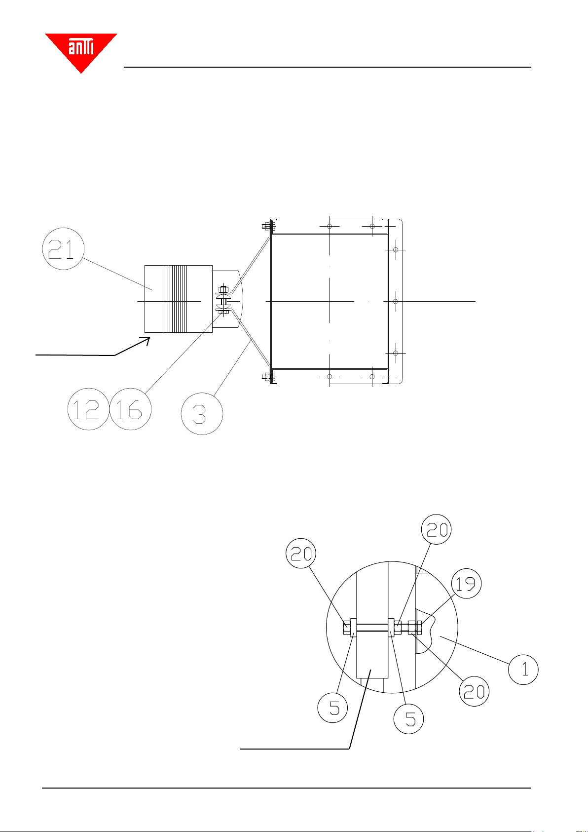
COMPRESS TO 35 mm
Fig. 6. Attachment to the actuator.
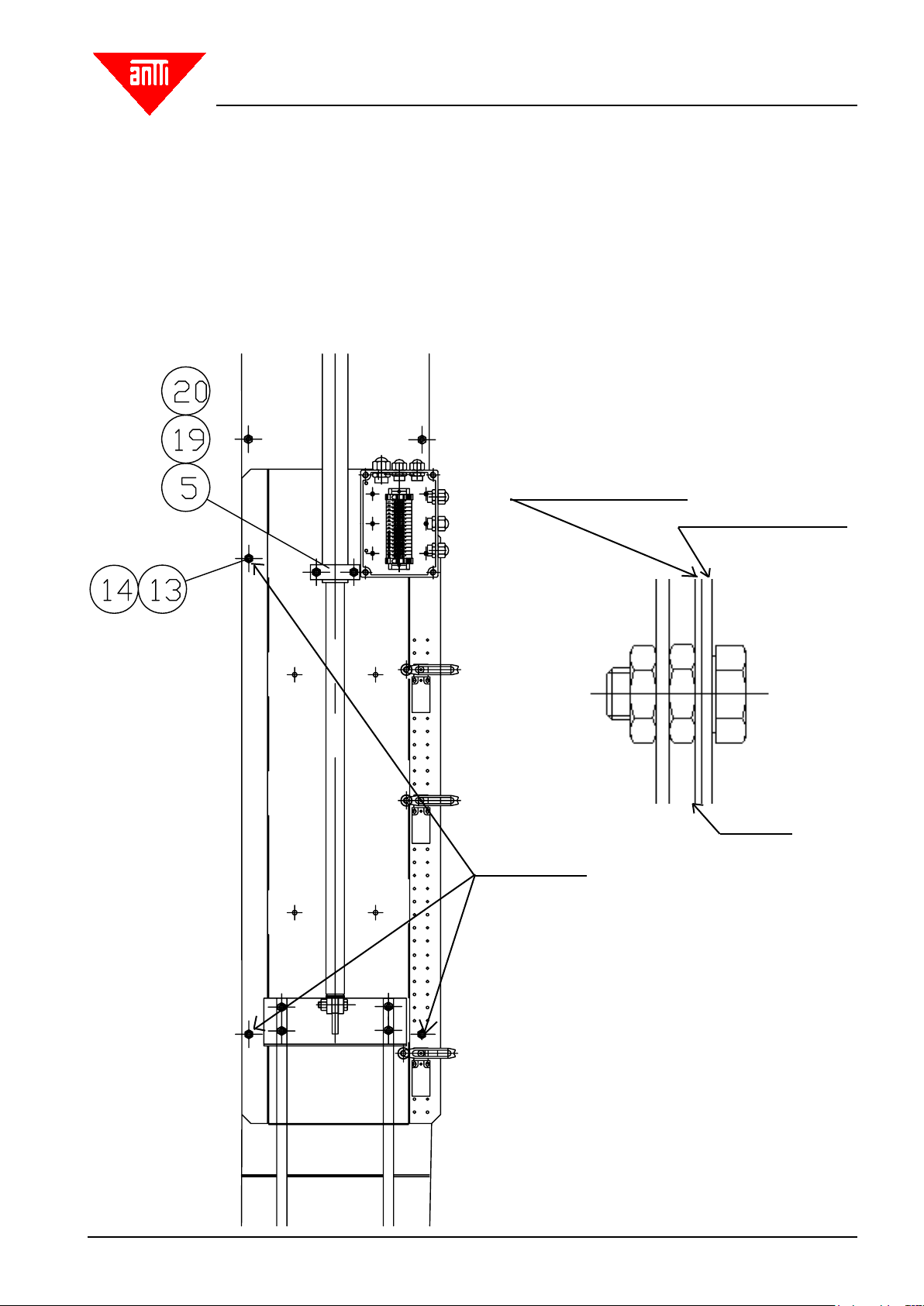
Fig 7. Guides
7. Guide
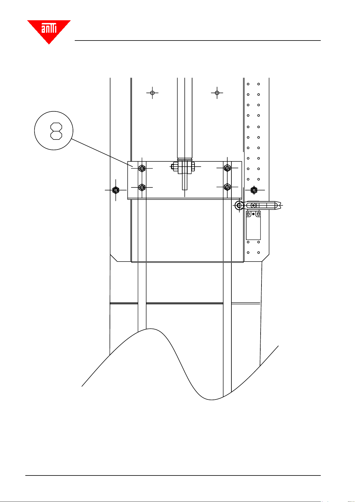
8. Intermediate rod bracket
9. Shutter plate rod
16. Hexagon screw M12x50
17. Nut M12
Attach the lower ends of the shutter plate
rodsas shown in Fig. 5. Compress the spring to 35mm
by tightening the nut.
Install the rod guides (Fig. 7, part 7) at regulardistances.
Cut the shutter plate rod to such a length that the inter-
mediate rod bracket (Fig. 8, part 8) falls on the lower
limit switch as the shutterplate is closed. Drill 8 mm holes
in the rods for attachment. If necessary, place washers
underthe screws so as to prevent the screw capsfrom
touching the frame plate.
Install the uppermost limit switch in the uppermost
attachment holes.
Finally, lift the intermediate rod bracket to a level where
it can be xed to the linear actuator (Fig. 6).
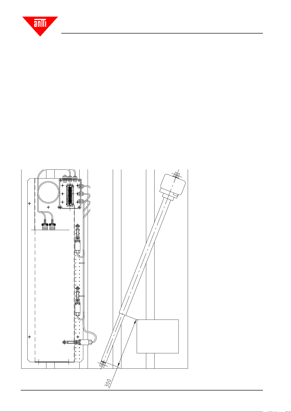
Fig 5. Fixing the lower end of the shutter plate rod (Fig.
1, detail DET 2) Note that the shutter plate edge must
point away from the elevator pipes.