Precautions
Read these instructions before installation. Configuration may
be easier before installation.
Install or remove thermometer using a wrench on the hex fitting
only. Do not attempt to turn by forcing the housing.
Use a thermowell appropriate for the process.
Do not exceed maximum allowable housing temperature.
Due to the hardness of 316 stainless steel, it is recommended
that a thread sealant be used to ensure leak-free operation.
Normal Operation
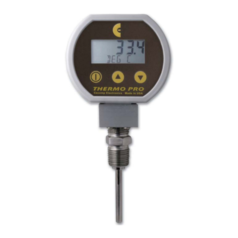
To turn the unit on, press the left front power button.
The display segments are tested.
The actual temperature and units are displayed and updated
approximately 4 times per second.
The factory default configuration is °F, 5 minute auto shutoff
and MAX/MIN disabled.
The auto shutoff timer is reset whenever any button is pressed.
To shut off the unit manually at any time, press and hold the
power button until OFF is displayed (up to about 5 seconds
total if MAX/MIN is enabled) and then release the button.
If the unit is configured with an auto shutoff time, a five second
warning period is provided prior to auto shutoff, during which
the display indicates OFF. Press any button to reset timer.
If so equipped, the optional display backlighting can be turned
on by momentarily pressing a button whenever the thermom-
eter is on. The backlighting will turn on for one minute and then
automatically shut off. This also restarts the auto shutoff timer.
The display backlighting will not be apparent under bright
lighting conditions.
Temperature Unit Selection
To change temperature units, press and hold the (up) button
until the temperature indication is blank and only the tempera-
ture units are displayed.
Then use the or buttons to select the desired temperature
units. Standard units are Fahrenheit, Celsius, and Kelvin.
When the desired units are displayed, press and release the
power button to save the selection and exit the change mode.
If no buttons are pressed for 15 seconds, the unit will automati-
cally save the selection and exit the change mode.
Auto Shutoff Time Selection
To change the auto shutoff time, press and hold the (down)
button until the auto shutoff time is displayed.
The lower display will indicate AST M if the auto shutoff time
displayed on the upper segments is in minutes, and AST H
if it in hours.
Use the or buttons to select 0, 1, 2, 5, 10, 15, 20, or 30
minutes, or 1, 2, 4, or 8 hours.
Setting the time to zero to disables the auto shutoff timer and
the thermometer will stay on until manually shut off or until
the batteries are depleted. Use the power button to turn the
thermometer off when not in use to conserve battery life.
When the desired auto shutoff time is displayed, press and
release the power button to save the selection and exit the
change mode.
If no buttons are pressed for 15 seconds, the unit will automati-
cally save the selection and exit the change mode.
User Configuration Mode
With the unit off, press and hold the button. Then press
the power button. Release buttons when the display indicates
CFG.
Before the unit enters the Configuration Mode, the display
initially indicates _ _ _ _ with the first underscore blinking,
and with CFGPC on the character display.
Note: The unit will automatically revert to normal operation if no
buttons are operated for approximately 15 seconds. To cancel
and return to normal operation, press and release the power
button without entering any pass code numbers.
Enter the user configuration pass code (3510 factory default):
Use the or buttons to set the left-most digit to 3.
Press and release the power button to index to the next posi-
tion. The 3 will remain, and the next position will be blinking.
Use the or buttons to select 5.
Press and release the power button to index to the next posi-
tion. 3 5 will remain, and the third position will be blinking.
Use the or buttons to select 1.
Press and release the power button to index to the next posi-
tion. 3 5 1 will remain, and the fourth position will be blinking.
Use the or buttons to select 0.
Press and release the power button to proceed with configura-
tion procedures. Note: If an incorrect pass code is entered, the
unit will return to the start of the pass code entry sequence.
MAX/MIN configuration
The upper display will be blank.
Use the or buttons to select from the following:
MX/MN Both highest and lowest values will be captured
MX/-- Only highest value measured will be captured
--/MN Only lowest value measured will be captured
--/-- Capture feature is disabled
Press and release the power button to move on to the next
parameter.
MAX/MIN memory
The upper display will indicate clr.
Use the or buttons to select from the following:
AUTO Maximum and Minimum values will automatically
be cleared whenever the unit shuts off.
MAN Maximum and Minimum values will be retained
and must be cleared manually as desired.
Press and release the power button to save the user configura-
tion and restart the unit.
Maximum and Minimum Readings
Thermometers are normally configured with maximum and
minimum capture functions disabled. One or both can be
enabled in the User Configuration mode.
If enabled, step the unit through the display modes by pressing
the power button for about 1 second until the display indicates
either MAX or MIN or degree units. The display mode cycles
through the following steps:
MAX mode: The maximum temperature is shown with the
lower display alternating between MAX and the degree units.
The thermometer may be left in this mode if a display of the
maximum reading is desired.
MIN mode: The minimum temperature is shown with the lower
display alternating between MIN and the degree units. The
thermometer may be left in this mode if a display of the mini-
mum reading is desired.
Normal mode: The current temperature and the degree units
are displayed.
To manually reset the memory, press and continue to hold the
power button until the display indicates clr (about 3 seconds
total) and then release the button. The stored maximum and
minimum values are cleared. The unit returns to normal opera-
tion with the display indicating the current temperature.
The memory may be configured to be automatically cleared
when the unit shuts down, or may be configured to retain the
maximum and minimum values at shutoff.
Calibration Mode
Select the temperature units for calibration prior to entering the
calibration mode. The use of Fahrenheit or Celsius is assumed
in this procedure.
To enter the calibration mode, begin with the unit powered off,
and press and hold the button. Then press the power button.
Release all buttons when the display indicates CAL.
Before the unit enters the Calibration Mode, the display initially
indicates _ _ _ _ with the first underscore blinking, and with
CALPC on the character display.
Enter the user-modifiable pass code (3510 factory default) as
described in the previous section:
The unit enters and remains in the Calibration Mode until
restarted manually or power is removed. While in the
Calibration Mode, the auto shutoff timer is disabled, the dis-
play backlight (if so equipped) is disabled, and the Max/Min
feature is disabled.
The unit is calibrated at ice point and at a temperature above
ice point. For general service, the full scale temperature is
normally used for the second point. However, if a particular
temperature is of critical interest it may be used instead for
greatest accuracy at that point.
When the applied temperature is below approximately 12°C (or
54°F), the unit will automatically select the ice-point calibra-
tion mode.
Calibration Procedure
Upon successful pass code entry, the upper segments of the
display will indicate the RTD probe temperature. The lower
segments of the display will alternate as indicated below.
Note: To store the calibration parameters and exit calibration
mode at any time, press and hold the power button until the
display indicates - - - - .
Ice-point calibration
Apply 0.0°C or 32.0°F to the RTD.
The lower display will alternate between ICE and DEG C or
DEG F.
Use the and buttons to adjust the display to indicate
0.0°C or 32.0°F.
Span calibration
Apply full-scale temperature to the RTD. The lower display will
alternate between CAL and DEG C or DEG F.
Use the and buttons to adjust the upper display to indi-
cate the desired temperature value.
To store the calibration parameters and exit calibration mode,
press and hold the power button until the display indicates
- - - - .
Changing the User-Defined Pass Codes
Configuration pass code: With the unit off, press and
hold the button to view and/or change the user configuration
pass code. Then press the power button. Release all buttons
when the display indicates CFG.
Calibration pass code: With the unit off, press and hold
the button to view and/or change the user calibration pass
code. Then press the power button. Release all buttons when
the display indicates CAL.
Before the unit enters the view or change pass code mode,
the display initially indicates _ _ _ _ with the first underscore
blinking, and CFGPC or CALPC on the character display.
Note: The unit will automatically revert to normal operation if no
buttons are operated for approximately 15 seconds. To cancel
and return to normal operation, press and release the power
button without entering any pass code characters.
Enter access code 1220
Use the and buttons to set the left-most digit to 1.
Press and release the power button to index to the next posi-
tion. The 1 will remain, and the next position will be blinking.
Use the and buttons to select 2.
Press and release the power button to index to the next posi-
tion. 1 2 will remain, and the third position will be blinking.
Use the and buttons to select 2.
Press and release the power button to index to the next posi-
tion. 1 2 2 will remain, and the fourth position will be blinking.
Use the and buttons to select 0.
Press and release the power button to proceed. Note: If an
incorrect access code was entered, the unit will return to the
start of the access code entry sequence.
Once the correct access code has been entered, the display
will indicate the existing user-defined pass code with CFGPC
or CALPC on the character display.
Operate the or button to select the first character of the
new pass code.
When the correct first character is being displayed, press and
release the power button to proceed to the next pass code
character.
Repeat above until the entire pass code is complete.
To exit the view or change pass code mode, press and hold the
power button. Release the button when the display indicates
– – – – to restart the unit.
cecomp.com
1220 American Way Libertyville, IL 60048
Phone: 800-942-0315 Fax: 800-949-7502
© 08-09
Cecomp ThermoPro®Battery Powered Temperature Indicator Instructions T16B, T16BBL
BSOLUTE ROCESS NSTRUMENTS, Inc.
Division of
MOD-TRONIC Instruments ·Brampton, ON · 905-457-6322 or 1-800-794-5883 ·sales@mod-tronic.com · www.mod-tronic.com


