manuals.online logo
Brands
  1. Home
  2. •
  3. Brands
  4. •
  5. Mod-tronic
  6. •
  7. Measuring Instrument
  8. •
  9. Mod-tronic Love Controls UPT 1000 Installation and operating instructions

Mod-tronic Love Controls UPT 1000 Installation and operating instructions

Model UPT 1000 – Universal Process-Temperature Indicator
Specifications - Installation and Operating Instructions
949-0542
PHYSICAL DATA
Selectable Inputs: Thermocouple, RTD, DC Voltage, or DC cur-
rent.
Input Impedance: Thermocouple = 3 megohms, Current = 10
ohms, Voltage = 5000 ohms.
RTD Excitation Current: 200µA.
Display: Two 4-1/2 digit LCD.
Accuracy: ±0.25% of span; ±1 least significant digit.
Maximum Overload: Current = 110mA, Voltage = 25Vdc.
Resolution: 1 count, 1 degree or 0.1 degree selectable.
Drift Over Temperature: ±0.02% (200 ppm) per ºC typical,
±0.05% (500 ppm) maximum.
Memory Backup: Non-Volatile EEprom.
Response Time: 2 readings per second.
Operating Temperature: 32 to 104ºF (0 to 40ºC).
Humidity Conditions: 0 to 40% Non-Condensing.
Power: 9V battery.
Battery Life: 200 hours typical.
Case Material: Anodized Aluminum with Plastic end caps.
Dimensions: 6.8”L x 2.8”W x 0.9”D (172.7 x 71 x 22.9 mm).
LOVE CONTROLS Division
Phone: 800/828-4588 or 219/879-8000
DWYER INSTRUMENTS, INC. • P.O. BOX 338 websites: www.love-controls.com or www.dwyer-inst.com
MICHIGAN CITY, INDIANA 46361-0338, U.S.A. Fax: 219/872-9057 e-mail: info@dwyer-inst.com
Lit-By Fax: 888/891-4963
Introduction
The Love Controls UPT 1000 Digital Hand-Held
Universal Process/Temperature Indicator is a
microprocessor based precision general-purpose
thermometer and process indicator designed for use
with a multitude of standard inputs. These inputs
include Type J, K, T, E, R, S, B, and N Thermocouples
as well as 100Ω2/3-wire Platinum, 120ΩNickel, and
1000ΩPlatinum RTDs.
In addition to these temperature inputs the UPT 1000
is capable of measuring current inputs (4-20 mAdc)
and voltage inputs (0 – 10 Vdc) making it an ideal
instrument for calibrating and validating a variety of
process instruments.
Standard features include: Standard ANSI mini-jack
connector or removable screw terminal type plug,
peak/valley indication, full degree or tenth of a degree
resolution in both Fahrenheit or Celsius as well as an
impressive set of fully scalable user selectable engi-
neering units, 20 minute auto power-off to conserve
battery life (can be disabled), and backlight.
The Love Controls UPT 1000 is a class leading hand-
held indicator offering 0.25% full-scale accuracy over
thirteen common input ranges. The unit is packaged in
a sturdy extruded aluminum case that will help to
ensure years of service and dependability. The UPT
1000 is designed and manufactured in the USA and
carries a 1-year limited warranty.
Also available are a soft carrying case (L402-A), extra
screw type connectors (part No. 481-0199) and a
variety of ANSI connectors and handheld temperature
probes, offered in both kits or individually.
NOTE:
This instrument is shipped with a new 9V battery.
However, there is a protective plastic cap installed on
the battery terminals. This cap must be removed and
the battery connected to the battery terminal before
the instrument will function.Use only 9 Volt alkaline
type batteries such as Duracell®MN1604, or
Eveready®522, or equivalent. Zinc-carbon types,
often labeled Heavy-Duty are not recommended
because of their shorter life and increased potential
for leakage. Alkaline batteries are a better value
because they typically last up to three times longer in
this device. For battery installation see page 4.
Low Battery Indication
When the 9V battery is reaching the end of it’s life, the
“LOW BAT” indicator on the display will turn on.
Duracell®is a registered trademark of Duracell USA, a division of Duracell Inc.
Eveready® is a registered trademark of Eveready Battery Company Inc.
UPT1000 IOM 6/6/02 11:22 AM Page 1
1 Delta Park Blvd, #12 Brampton, ON L6T 5G1
Tel 905-457-6322 or 1-800-794-5883
Fax 905-457-4716 or 1-800-830-7122
sales@mod-tronic.com www.mod-tronic.com
Input Wiring
Thermocouples and RTD’s with mini plugs can plug
directly into the mini jack on the top of the instrument.
Thermocouples and RTD’s with stripped wire ends,
and current or voltage inputs can wire into the remov-
able plug.
•3wire RTD’s with mini plugs – Plugs into three ter-
minal mini jack.
• 2 wire RTD’s with mini plugs – Plug into two of the
three terminals of the three terminal mini jack. Align
the large terminal of the plug with the large terminal of
the jack. Place a jumper wire between terminals
2 and 3 of the removable plug.
Thermocouples with mini plugs – Plug into two of the
three terminals of the three terminal mini jack. Align
the large terminal of the plug with the large terminal of
the jack.
Input Ranges (Field Selectable)
Thermocouple Types
* These Input Types can be set for 0.1º display. If tem-
perature goes above 1999.9º the display will return to
whole degree resolution. The display will revert to 0.1º
when the temperature falls back below 2000º.
T/C
VOLTAGE
1 2 3 4
RTD
CURRENT
++
–
Wiring for
Removable Plug
Note: For 2 wire RTD, place a
jumper wire between terminals
2 and 3
Input
Type
Type J or
L* Iron
Constantan
Type K*
Chromel-
Alumel
Type T*
Copper-
Constantan
Type E*
Chromel-
Constantan
Range
1ºF
1ºC
-100 to +1607
-73 to +875
-200 to +2500
-129 to +1371
-350 to +750
-212 to +398
-100 to +1800
-73 to +982
Input
Type
Type R
PT 13%-
PT
Type S
PT 10%-
PT
Type B
PT 6% RE-
PT 30% RE
Type N* Ni
Chr Si-Ni Si
Range
1ºF
1ºC
0 to +3200
-17 to +1760
0 to +3200
-17 to +1760
+75 to +3276
+24 to +1802
-100 to +2372
-73 to +1300
RTD Types
Process Input Types
The 0-20 mAdc and 0-10 Vdc inputs are fully scalable
with a maximum of 32000 counts span placed any-
where within the range of -19999 to +19999. Decimal
point position is adjustable from zero place (19999),
tenths (1999.9), hundredths (199.99), thousandths
(19.999) or ten thousandths (1.9999).
Items that can be Accessed Directly from
Keypad
On Off Operation:
Pressing turns power on, pressing again turns
power off. The unit will automatically shut off if
there is no activity for 20 minutes. To defeat the
automatic shut off, when turning the unit on press
and hold the down and then press . When
the unit is turned on, the entire display will be on
momentarily, then the display will sequence to the
home position, with the input type being displayed in
the lower left display for a few seconds.
To display the input type at any time, refer to “Items
that can be accessed through the menu”.
Display Backlight:
Press to turn the backlight on, again to turn the
backlight off. The Backlight will automatically turn off
after 2 minutes to conserve battery power.
Display Hold:
Pressing then releasing will freeze the display
and turn on the “HOLD” annunciator.
Input Type:
Press the key to display the input type. The lower
left display will show the input type for a few seconds.
Input
Type
100 Ohm
Platinum
0.00385 DIN
Curve*
120 Ohm
Nickel
0.00628 US
Ind. Curve*
100 Ohm
Platinum
0.00385 DIN
Curve*
Range
1ºF
1ºC
-328 to +1607
-200 to +875
-112 to +608
-80 to +320
-328 to +1607
-200 to +875
ON
OFF
BACKLIGHT
LOW BAT
HOLD %RH MPS
PPM
mBAR
CO
2
°C°F°F°F
FPM
PSI kPa
H O HG
2
mm in
Entire display on Home position
with input type
displayed
Home position
Display sequence at power up.
HOLD
▲
HOLD
°F
INPUT
▲
ON
OFF
BACKLIGHT
LOW BAT
HOLD %RH MPS
PPM
mBAR
CO
2
°C°F°F°F
FPM
PSI kPa
H O HG
2
mm in
Entire display on Home position
with input type
displayed
Home position
Display sequence at power up.
HOLD
▲
HOLD
°F
INPUT
▲
ON
OFF
BACKLIGHT
LOW BAT
HOLD %RH MPS
PPM
mBAR
CO
2
°C°F°F°F
FPM
PSI kPa
H O HG
2
mm in
Entire display on Home position
with input type
displayed
Home position
Display sequence at power up.
HOLD
▲
HOLD
°F
INPUT
▲
ON
OFF
BACKLIGHT
LOW BAT
LOW BAT
HOLD %RH MPS
MPS
PPM
PPM
mBAR
CO
2
°C°F°F°F
FPM
PSI kPa
H O HG
2
mm in
mm in
Entire display on Home position
with input type
displayed
Home position
with input type
displayed
Home position
Display sequence at power up.
HOLD
▲
HOLD
°F
INPUT
▲
ON
OFF
BACKLIGHT
LOW BAT
HOLD %RH MPS
PPM
mBAR
CO
2
°C°F°F°F
FPM
PSI kPa
H O HG
2
mm in
Entire display on Home position
with input type
displayed
Home position
Display sequence at power up.
HOLD
▲
HOLD
°F
INPUT
▲
°F
°F
HOLD
▲
STORE
▲
ENTER
INDEX
ON
OFF
BACKLIGHT
LOW BAT
HOLD %RH MPS
PPM
mBAR
CO
2
°C°F°F°F
FPM
PSI kPa
H O HG
2
mm in
Entire display on Home position
with input type
displayed
Home position
Display sequence at power up.
HOLD
▲
HOLD
°F
INPUT
▲
ON
OFF
BACKLIGHT
LOW BAT
HOLD %RH MPS
PPM
mBAR
CO
2
°C°F°F°F
FPM
PSI kPa
H O HG
2
mm in
Entire display on Home position
with input type
displayed
Home position
Display sequence at power up.
HOLD
▲
HOLD
HOLD
°F
INPUT
▲
UPT1000 IOM 6/6/02 11:22 AM Page 2
Items that can be Accessed through the
Menu
How To Use The Menu
To access the menu, press to enter the menu
mode. Continue pressing until the desired
menu item is displayed. When the instrument is in
the menu mode, the key will function as the
“INCREMENT” key, and the key will function as
the “DECREMENT” key.
When the desired menu item is displayed, use the
and keys to modify the menu item to the
desired value, then press to store the value in
memory. If the enter key in not pressed, the original
value will be retained in memory and not changed.
To exit the menu mode, scroll to the home position.
The instrument will automatically exit the menu mode
if no key is pressed for one minute.
Reading the Peak and Valley Values
The Peak ( ) feature stores the highest reading
the monitor has measured since the last reset or
Power on. The Valley ( ) features stores the low-
est reading. At Power On, and are reset to
the present reading.
To view the Peak or Valley values, press until the
lower left display reads or . When or
is displayed, pressing will reset the value to the
present value.
Display Reading Peak Value
Display Reading Valley Value
Setting the Input Type
Press until the lower left display reads . The
present input type will be displayed in the upper dis-
play. To change the input type, scroll through the
selections using the and keys. When the
desired input type is displayed, press key to
store.
Input Types:
Type “J” Thermocouple, Iron/Constantan (NIST)
Type “K” Thermocouple, Chromel/Alumel
Type “E” Thermocouple, Chromel/Constantan
Type “T” Thermocouple, Copper/Constantan
Type “N” Thermocouple, Nicrsil/Sisil
Type “R” Thermocouple, PT 13% RH/Pt
Type “S” Thermocouple, PT 10% RH/Pt
Type “b” Thermocouple, PT 6%/Rh/Pt 30%Rh
120 ohm Nickel RTD
100 ohm Platinum (DIN 0.00385 Ω/Ω/ºC)
1000 ohm Platinum (DIN 0.00385 Ω/Ω/ºC)
DC Current Input 0 to 20 mA
DC Voltage Input 0.0 to 10.0 volts
Setting the Units
If the input type is set for a thermocouple or RTD, the
units may be set to ˚F or ˚C. If the input type is set for
current or voltage, the units may be set for any of the
following:
, kPa, Pa, PSI, in Hg, mm Hg, in H2O, mm H2O,
mBAR, BAR, PPM CO2, PPM CO, PPM, FPM,
MPS,%RH,˚C, and ˚F
To change the input units, press until the lower
display reads .
Scroll through the selections using the and
keys. When the desired selection is displayed,
press to store.
Setting the Decimal Point
For Thermocouple and RTD inputs, the instrument
may be set to no decimal point (0) or one decimal
point (0.0). For current or voltage inputs, the decimal
point may be set to:
0
0.0
0.00
0.000 Display in the Decimal Point mode.
.0000
To change the decimal point, press until the
lower left display reads
Scroll through the selections using the and
keys. When the desired selection is displayed, press
to store.
Setting or Viewing Scale Low and Scale High
For Thermocouple and RTD inputs, the Scale Low
( ) and Scale High ( ) values are viewable
only, and represent the low end and high end of the
range.
For Current and Voltage inputs the display may be
°F
°F
HOLD
▲
STORE
▲
ENTER
INDEX
°F
°F
HOLD
▲
STORE
▲
ENTER
INDEX
ON
OFF
BACKLIGHT
LOW BAT
HOLD %RH MPS
PPM
mBAR
CO
2
°C°F°F°F
FPM
PSI kPa
H O HG
2
mm in
Entire display on Home position
with input type
displayed
Home position
Display sequence at power up.
HOLD
▲
HOLD
°F
INPUT
▲
°F
°F
HOLD
▲
STORE
▲
ENTER
INDEX
.
..
.
.
ON
OFF
BACKLIGHT
LOW BAT
HOLD %RH MPS
PPM
mBAR
CO
2
°C°F°F°F
FPM
PSI kPa
H O HG
2
mm in
Entire display on Home position
with input type
displayed
Home position
Display sequence at power up.
HOLD
▲
HOLD
°F
INPUT
▲
°F
°F
HOLD
▲
STORE
▲
ENTER
INDEX
°F
°F
HOLD
▲
STORE
▲
ENTER
INDEX
°F
°F
HOLD
▲
STORE
▲
ENTER
INDEX
°F
°F
HOLD
▲
STORE
▲
ENTER
INDEX
°F
°F
HOLD
▲
STORESTORE
▲
ENTER
INDEX
°F
°F
HOLD
▲
STORE
▲
ENTER
INDEX
°F
°F
HOLD
▲
STORESTORE
▲
ENTER
INDEX
°F
°F
HOLD
▲
STORE
▲
ENTER
INDEX
°F
°F
HOLD
▲
STORE
▲
ENTER
INDEX
°F
°F
HOLD
▲
STORE
▲
ENTER
INDEX
°F
°F
HOLD
▲
STORE
▲
ENTER
INDEX
°F
°F
HOLD
▲
STORE
▲
ENTER
INDEX
°F
°F
HOLD
▲
STORE
▲
ENTER
INDEX
°F
°F
HOLD
▲
STORE
▲
ENTER
INDEX
°F
°F
HOLD
▲
STORE
▲
ENTER
INDEX
°F
°F
HOLD
▲
STORE
▲
ENTER
INDEX
°F
°F
HOLD
▲
STORE
▲
ENTER
INDEX
°F
°F
HOLD
▲
STORE
▲
ENTER
INDEX
°F
°F
HOLD
▲
STORE
▲
ENTER
INDEX
°F
°F
HOLD
▲
STORE
▲
ENTER
INDEX
°F
°F
HOLD
▲
STORE
▲
ENTER
INDEX
°F
°F
HOLD
▲
STORE
▲
ENTER
INDEX
ON
OFF
BACKLIGHT
LOW BAT
HOLD %RH MPS
PPM
mBAR
CO
2
°C°F°F°F
FPM
PSI kPa
H O HG
2
mm in
Entire display on Home position
with input type
displayed
Home position
Display sequence at power up.
HOLD
▲
HOLD
°F
INPUT
▲
°F
°F
HOLD
▲
STORE
▲
ENTER
INDEX
°F
°F
HOLD
▲
STORE
▲
ENTER
INDEX
INPUT
▲
INPUT
▲
INPUT
▲
Display the Input
Type Mode
INPUT
▲
°F
°F
HOLD
▲
STORE
▲
ENTER
INDEX
INPUT
▲
UPT1000 IOM 6/6/02 11:22 AM Page 3
Display Meaning Action Required
Underflow or Overflow:
Process value has
exceeded input range
ends.
None, input signals
may go beyond input
range ends.
A/D converter failure. Factory service
required.
Non-volatile memory
failure.
Factory service
required.
Open RTD third wire.
Correct or replace sen-
sor. To reset use the
and keys.
Ambient range of the
instrument exceeded
or RJC sensor broken.
Correct ambient tem-
perature conditions. If
error is still present,
factory service is
required.
The input has exceed-
ed the range of the
A/D converter.
Check input polarity,
input signal value, and
correct.
scaled to almost any desired value. For a current
input, Scale Low would be the displayed value with an
input of 0mA, and Scale High would be the displayed
value with an input of 20mA. For a voltage input,
Scale Low would be the displayed value with an input
of 0V, and Scale High would be the displayed value
with an input of 10V. Scale Low and Scale High may
be set to any value from -19999 to +19999 as long as
the following conditions are met:
1. Scale High must be higher then Scale Low.
2. Scale High must not be more than 32000 counts
above Scale Low.
To adjust Scale High or Scale Low, press until
the lower left display reads or , then use
the and keys to set the desired value.
Press to store the value.
Display Reading Scale Low
For a current input, the actual input range is 0-20mA.
For an input range of 4-20mA, the actual Scale Low
setting must be offset by 20% to allow for the differ-
ence between 0MA (the actual low end of the analog
scale) and 4mA (the desired low end of the analog
scale).
Use the following formula to calculate the Scale Low
setting:
= Desired scale low end- ((Desired -
Desired scale low end) ÷4))
Example 1: The unit is wired to a differential pressure
transmitter with a range of -0.25 to +0.25 inches of
water column and an output of 4-20mA.
= -0.250 - ((+0.250 - -0.250) ÷4) = -0.250 -
(0.500÷4) = -0.250 - 0.125 = -0.375
Example 2: The unit is wired to a Carbon Monoxide
transmitter with a range of 0-1000 PPM and an output
of 4-20mA.
= 0 - ((1000 - 0) ÷ 4) = 0 - (1000 ÷ 4) = 0 - 250
= -250
°F
°F
HOLD
▲
STORE
▲
ENTER
INDEX
ON
OFF
BACKLIGHT
LOW BAT
HOLD %RH MPS
PPM
mBAR
CO
2
°C°F°F°F
FPM
PSI kPa
H O HG
2
mm in
Entire display on Home position
with input type
displayed
Home position
Display sequence at power up.
HOLD
▲
HOLD
°F
INPUT
▲
°F
°F
HOLD
▲
STORE
▲
ENTER
INDEX
°F
°F
HOLD
▲
STORE
▲
ENTER
INDEX
.
.
.
.
.
.
.
°F
°F
HOLD
▲
STORE
▲
ENTER
INDEX
©Copyright 2002 Dwyer Instruments, Inc. Printed in U.S.A. 6/02 FR# 949-0542
LOVE CONTROLS Division
Phone: 800/828-4588 or 219/879-8000
DWYER INSTRUMENTS, INC. • P.O. BOX 338 websites: www.love-controls.com or www.dwyer-inst.com
MICHIGAN CITY, INDIANA 46361-0338, U.S.A. Fax: 219/872-9057 e-mail: info@dwyer-inst.com
Lit-By Fax: 888/891-4963
or
or
or
or
or
or
ON
OFF
BACKLIGHT
LOW BAT
HOLD %RH MPS
PPM
mBAR
CO
2
°C°F°F°F
FPM
PSI kPa
H O HG
2
mm in
Entire display on Home position
with input type
displayed
Home position
Display sequence at power up.
HOLD
▲
HOLD
°F
INPUT
▲
Diagnostic Error Messages
Battery Installation
Remove two screws holding the bottom endcap
labeled BATTERY in place and remove it. Connect the
battery to the enclosed battery clip observing correct
polarity. Insert the battery in the case. Be careful not to
trap the wires between the case or foam pad, which
retains the battery. This could make it difficult to install
the battery or remove it later for replacement. Be sure
the rubber gasket is properly seated in the gasket
channel and replace the endcap. Note that the end-
cap will only fit one way because the holes are slightly
off-center. Place the “Z” shaped wrist strap clip in one
of the screw recesses and replace the screw. Do not
overtighten. Attach the wrist strap to the clip.
UPT1000 IOM 6/6/02 11:22 AM Page 4
1 Delta Park Blvd, #12 Brampton, ON L6T 5G1
Tel 905-457-6322 or 1-800-794-5883
Fax 905-457-4716 or 1-800-830-7122
sales@mod-tronic.com www.mod-tronic.com

Other Mod-tronic Measuring Instrument manuals

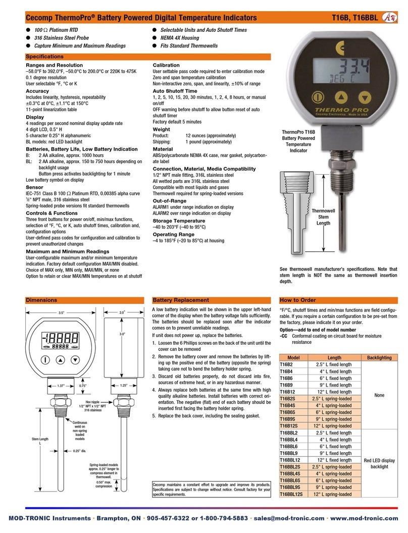
Mod-tronic Cecomp ThermoPro T16B Series User manual

Mod-tronic

Mod-tronic Cecomp ThermoPro T16B Series User manual

Mod-tronic Cecomp ThermoPro T16B Series User manual

Mod-tronic

Mod-tronic Cecomp ThermoPro T16B Series User manual

Popular Measuring Instrument manuals by other brands

THORLABS PAX1000 quick reference

THORLABS

THORLABS PAX1000 quick reference

UNAOHM AP 401 Full HD user manual

UNAOHM

UNAOHM AP 401 Full HD user manual

HM Digital FLM-3 user guide

HM Digital

HM Digital FLM-3 user guide

WIKA CPH6400 operating instructions

WIKA

WIKA CPH6400 operating instructions

Extech Instruments HD700 user guide

Extech Instruments

Extech Instruments HD700 user guide

Micromeritics AquaPrep 055 Operator's manual

Micromeritics

Micromeritics AquaPrep 055 Operator's manual

Sanwa PC710 instruction manual

Sanwa

Sanwa PC710 instruction manual

Eaton K1650 instruction manual

Eaton

Eaton K1650 instruction manual

Fluke 434-II Manual supplement

Fluke

Fluke 434-II Manual supplement

Aiwa CSD-A310 HA Service manual

Aiwa

Aiwa CSD-A310 HA Service manual

Lutron Electronics CM-9930R Operation manual

Lutron Electronics

Lutron Electronics CM-9930R Operation manual

Deviser S7200 user guide

Deviser

Deviser S7200 user guide

montwill M1 user manual

montwill

montwill M1 user manual

Geevon W208703 user manual

Geevon

Geevon W208703 user manual

Kaman ThreadChecker user manual

Kaman

Kaman ThreadChecker user manual

OVMS OVMS user guide

OVMS

OVMS OVMS user guide

YOKOGAWA 751552 user manual

YOKOGAWA

YOKOGAWA 751552 user manual

Reed Instruments R2310 instruction manual

Reed Instruments

Reed Instruments R2310 instruction manual

manuals.online logo
manuals.online logoBrands
  • About & Mission
  • Contact us
  • Privacy Policy
  • Terms and Conditions

Copyright 2025 Manuals.Online. All Rights Reserved.