modbar STEAM Series User manual

manual
modbar - steam system
Modbar Steam is a stand-alone steaming system for retail environments
requiring powerful steam capacity in a modern, minimal aesthetics.
Ideal for cafes looking to complete their Modbar system; add steam
capacity to an existing bar; or build an independent beverage-heating
workstation.

modbar - steam system
Operating Manual V1.2 - 09/2020
MAN.23.01
EN
certications available:
Printed on recycled paper.
La Marzocco S.r.l.
Via La Torre 14/H
Località La Torre
50038 Scarperia e San Piero
(Firenze) - ITALIA
www.modbar.com | @modbar
T: +39 055 849 191
F: +39 055 849 1990
Original instructions veried by the
manufacturer.
Scan QR Code to view the complete
Software Programming Guide available on
the modbar website International or US &
Canada.
Chapters
1. General Warnings and Safety Specications
2. Denition of Available Models
3. Installation
4. Machine Operation and Dispensing Operation
5. Maintenance and Periodic Cleaning Operations
6. De-commissioning and Demolition
7. Mandatory Maintenance and Check-up Operations
page 3
page 8
page 10
page 16
page 18
page 20
page 21

EN
3
1) Important safeguards
• The weighted sound pressure
level of the machine is lower
than 70dBA.
• Use, cleaning and
maintenance of this
Modbar Steam machine
are realized by people
(including children more
than 8 years of age) with
reduced physical, sensory
or mental capabilities, or
lack of experience and
knowledge, as long as they
have been given supervision
or instructions concerning
the use of the appliance
by a person responsible
for their safety and if they
understand dangers.
• Children should be
supervised to ensure that
they do not play with the
appliance.
• Keep the appliance and
1. General Warnings and Safety Specications
WARNING
This machine is for professional
use only and should be installed
in locations where its use and
maintenance is restriced to
trained personnel. Children are
forbidden to operate or play with
the machine.
WARNING
This machine is not suitable for
outdoor use. Jets of water should
not be used to clean the machine,
nor should it be placed where
water jets are used.
WARNING
As already mentioned in
the preceding notes, the
manufacturer shall not be held
responsible for damage to
objects, animals and/or people
whenever the machine has not
been installed according to the
instructions contained in this
manual, and is not used to do
what it was designed for (i.e.
preparing hot drinks).
WARNING
The Steam Tap must be placed in
a horizontal position on a counter
higher than 80 cm from the
ground. WARNING
Risk of re and electric shock.
Replace only with manufacturer’s
cord original spare part, see the
parts catalog.

EN
4
its cord out of the reach of
children less than 8 years
of age.
2) This operating manual
is an integral and essential
part of the product and
must be supplied to users.
Users are asked to read
the enclosed warnings and
cautions carefully, as they
provide valuable information
concerning safety during
installation, operation and
maintenance. This manual
must be kept in a safe
place and be available for
consultation to new and
experienced users alike.
3) Ensure product’s integrity
by inspecting the packaging,
making sure it presents no
signs of damage which might
have affected the enclosed
machine.
4) Check the machine’s
integrity after having carefully
removed the packaging.
Note: In case of doubt, do not go
on any further and contact your
dealer or retailer immediately. They
will send out specialized personnel
authorized to perform service on
the Modbar Steam machine.
5) Packaging (boxes, plastic
bags, foam parts and whatever
else) must not be left around
within easy reach of children,
due to the potential danger it
represents, nor be discarded
in the environment.
6) Check to see that data on
the rating plate corresponds
to those of the main electrical
supply which the machine will
be hooked up to.
7) The equipment must be
installed to comply with the
applicable federal, state or
local electrical and plumbing
codes. The installation
also must comply to the
manufacturer’s instructions,
and must be performed by
qualied and authorized
personnel.
8) Incorrect installation may
cause for injury/damages to
people, animals or objects, for
which the manufacturer shall
not be held responsible.
9) Safe electrical operation of
this device will be achieved
only when the connection to
the power outlet has been
completed correctly and
in observance of all local,
national, and international
electrical codes and safety
regulations, and particularly

EN
5
by grounding the unit.
Make sure grounding has
been done properly as it
represents a fundamental
safety requirement. Ensure
qualied personnel check
such connection.
10) Furthermore, you must
ensure that the capacity of
the available electrical system
is suitable for the maximum
power consumption indicated
on the Modbar Steam
machine.
11) We do not recommend
using adapters, multiple
plugs and/or extension cords.
If you cannot avoid using
them, make sure that they are
exclusively of the kind which
conforms to local, national,
and international electrical
codes and safety regulations,
being careful not to exceed
the power and current ratings
indicated on such adapters
and extension cords.
12) This device must be used
exclusively for the functions it
has been designed and built
for. Any other application is
inappropriate and dangerous.
The manufacturer shall not be held
responsible for any damages caused
by improper and/or irrational use.
This machine should not be
installed in kitchens.
13) Using any electrical
device requires that certain
fundamental rules be
observed. In particular:
• do not touch the device
with wet or humid hands
and feet;
• do not use the device while
having no shoes on your
feet;
• do not use extension cords
in bath or shower rooms;
• do not unplug the device
from the power outlet by
pulling on the power supply
cable;
• do not expose the device to
atmospheric agents (rain,
sun, etc.);
• do not allow children or
untrained people to use
this device;
• do not clean the control
panel with a wet cloth since
it is not watertight.
14) Before carrying out any
maintenance and/or cleaning
operations, turn the main
switch, which is located on
the front left of the machine,
to the “0” or “OFF” position,
and disconnect the machine

EN
6
from the electrical network
by unplugging the cord or
by switching off the relative
circuit breaker. For any
cleaning operation, follow
exclusively the instructions
contained in this manual.
15) In case the machine is
operating in a faulty manner
or breaks down, disconnect
it from the electrical network
(as described in the preceding
point) and close the water
supply valve. Do not attempt
to repair it. Contact a qualied
and authorized professional to
perform any repair. Any repairs
must be performed exclusively
by the manufacturer or by
an authorized centre using
only original parts. Non
compliance with the above
could compromise the safe
operation of the machine.
16) You should plan to
make use of an omnipolar
connector during installation,
as required by local, national,
and international electrical
codes and regulations.
17) In order to avoid dangerous
overheating problems, it is
recommended that the power
supply cable be fully unfurled.
18) Do not obstruct air intake
and exhaust grilles and, in
particular, do not cover the
cup warmer tray with cloths or
other items.
19) The machine’s power
supply cable must not be
replaced by users. In case the
power supply cable becomes
damaged, shut off the
machine and disconnect the
machine from the electctrical
network by switching off the
relative circuit breaker and
close off the water supply;
to replace the power supply
cord, contact qualied
professionals exclusively.
20) These instructions are also
available in an alternative
format on a website
https://modbar.com/support/
international/
https://modbar.com/support/us/
21) The machine should be
placed on a at counter
and must be placed in
settings with the following
temperatures:
Minimum room temperature:
5°C/41°F;
Maximum room temperature:
32°C/89°F.
22) Check the package to
make sure that the following

EN
7
A [mm]
B [mm]
C [mm]
WEIGHTModule [kg]
28) Dimensions and weights common to all
machines
A
C
B
D
EF
356
18
215
406
D [mm]
E [mm]
F [mm]
334
89
312
WEIGHTTap [kg] 3,5
accessories are included:
• 3 stainless steel braided
hoses for water connections;
• 5 mt of reinforced plastic
tubing for drainage;
• 9 hose clamp.
23) If the machine has
been temporarily housed
in settings with a room
temperature of less 0°C/32°F,
the machine must be placed
in a warmer environment in
order to gradually defrost the
hydraulic system prior to use.
24) Water pressure supply
must be between 0,2 and
0,6 MPa.
The maximum inlet water
pressure shall be at least
1,0 MPa (Denmark, Norway,
Sweden).
25) The machine is intended
to be permanently connected
to xed wiring, and it is
mandatory that a residual
current device (RCD) with
a rated residual operating
current not exceeding 30mA
is installed.
26) This machine is designed
only for preparing coffee and
hot drinks.
27) Any modication to the
equipment is prohibited;
the manufacturer cannot
be held liable for damage
to property, animals, and/
or persons if the equipment
undergoes technical
and aesthetic changes,
changes in performance
and characteristics, and in
general is tampered with in
one or more of its constituent
components.

EN
8
2. Denition of Available Models
This operating manual refers exclusively to the following models, of our own manufacture:
MODBAR, Steam System
1Steam Actuator Lever
2Steam Wand
3Extra Tap
4Power Switch
5Selector
6Refresh Button
7Pressure Gauge
8Pressurestat
9Water Inspection Window
10 Drain
11 Tap 1 Steam
12 Tap 2 Steam
13 Water Inlet
14 Power Inlet
15 Tap 1 Low Voltage
16 Tap 2 Low Voltage
17 Drain Tray Grate
Legend
Fig. 1 - STEAM System
2
4714
Steam Tap
Steam Module
13
16
15
17
1
8
10
12
11
9
6
5
3

EN
9
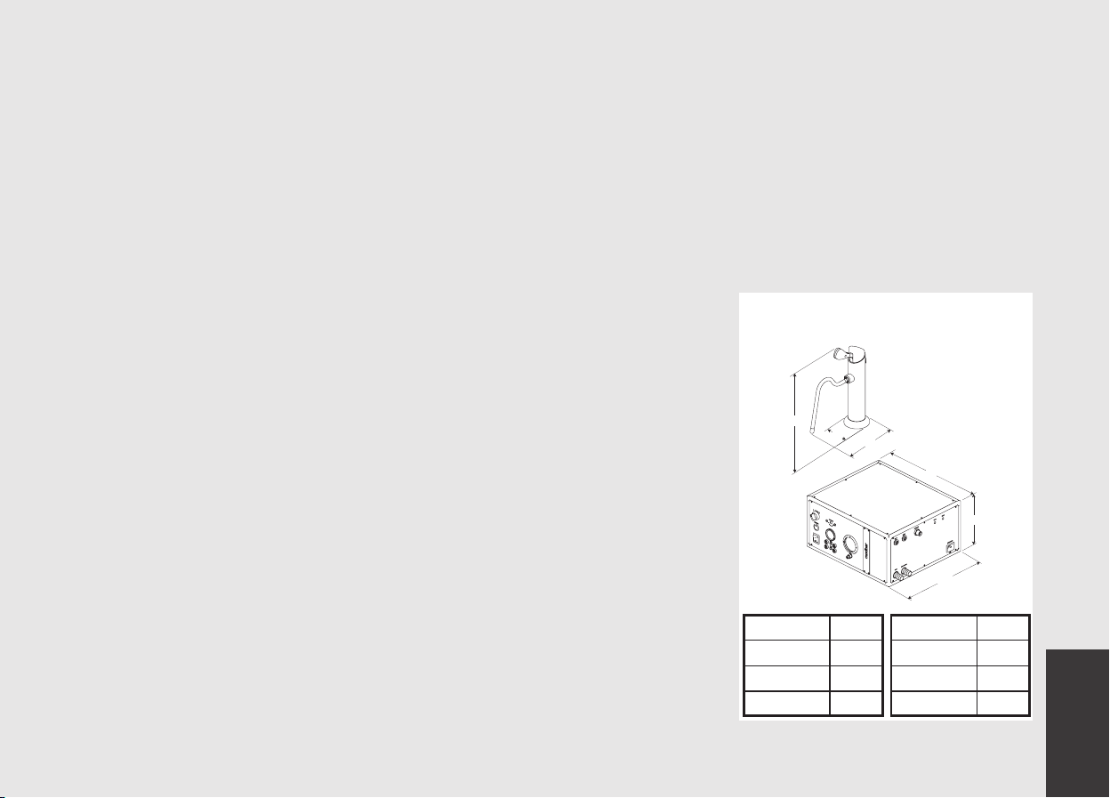
1) General Description
The machine is built in 1 and 2 steam
group versions and is essentially composed
of the following parts:
• Dispensing tap(s).
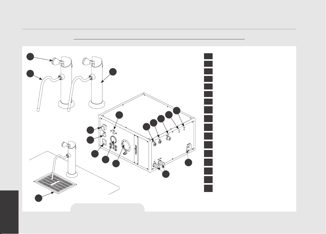
2) Description of the various parts
• Steam Boiler
The Steam Boiler consists of a cylindrical
tank, which is made of AISI 300 series
stainless steel. Each unit is subjected to a
hydraulic test, at a pressure of 6 bar, and
has an operating pressure of 1.7-1.8 bar.
The following is a list of effective volumes
and power ratings according to the number
of groups installed:
1 steam boiler 4,6 liters 3600 Watts
Covers are welded at either end of the
cylindrical tank and on one of them there
is a housing for the water heating element,
which allows the steam boiler to reach
operating pressure within approximately
10 minutes. The steam boiler has various
ttings used for safety devices, for
supplying hot water and steam, and for the
heating element.
It consists of AISI 300 stainless steel
tubes. Heating is accomplished through an
immersion-type plated heating element.
• Operating pressure of 1.7-1.8 bar,
controlled automatically through a
pressure switch.
• The pressure is displayed by means of a
pressure gauge with a scale of 0 to 3 bar.
• Safety device, based on an expansion
type mechanical valve, with counter-acting
spring adjusted to 2.5 bar.
• Testing: hydraulic test at 6 bar performed
on ready-to-use small boilers, at our
factory.
• Dispensing groups
They consist of a precision casting made
of stainless steel. The Modbar steam tap
is operated via a lever handle located on
top of the tap. This handle actuates a
valve that allows steam to pass through
the steam wand. To dispense steam, move
the lever handle from the closed position
to the open position.
• Exterior cover
The exterior consists of painted and
stainless sheet steel panels. To provide
good aesthetics, to optimize ergonometrics
for the operator and to reduce the chance
of damage to a minimum.
•Machine ETL plate:
•Machine CE plate:
MODEL: MFG. DATE:
MAX. PRESSURE: 0.25 MPaCAPACITY: 4.6L
208 Vac / 13A / 2,704W / 60hz. / 1-Phase
220-240 Vac / 14,4A / 3,306W / 60hz. / 1-Phase
READ OPERATING
MANUAL BEFORE USING
THIS EQUIPMENT
WATERSUPPLY:
3.8 l/min
MIN 0.24 MPa - MAX 0.6 MPa
CONFORMS TO UL STD 197
CERTIFIED TO CSA STD C22.2 NO.109
New Steam System 08/01/2018
SERIAL #:
PR000000
MADE IN
ITALY
MODEL: MFG. DATE:
MAX. PRESSURE: 0.25 MPaCAPACITY: 4.6L
220-240 V / 50/60Hz
READ OPERATING
MANUAL BEFORE USING
THIS EQUIPMENT
WATERSUPPLY:
3.8 l/min
MIN 0.24 MPa - MAX 0.6 MPa
New Steam System 01/08/2018
SERIAL #:
PR000000
14.4A / 3306W
MADE IN
ITALY
CONFORMS TO UL STD 197
CERTIFIED TO CSA STD C22.2 NO.109

EN
10
3. Installation
THE DETAILS ON THE LEFT DESCRIBE
HOW TO CONNECT EACH WIRE TO THE PLUG.
RESPECT ALSO THE LOCAL SAFETY
REGULATIONS.
MODEL/SERIES BOILER
GROUP V/Hz
RATED
POWER
(W)
RATED
INPUT
(A)
POWER CORD
SIZE (mm²)
MODBAR
NEW STEAM
1GR / 2GR
A
C220-240V/50-60Hz
AC208/60Hz
3306 14,4 SEE ELECTRICAL
2704 CONNECTIONS
FOR DETAILS
WARNING
13
POWER CORD:
1 X BLUE (NEUTRAL)
1 X BROWN (PHASE)
1 X YELLOW & GREEN (GROUND)
3 X WIRES
220V
WARNING
In order to prevent cracks
or leakage: do not store or
install the Steam machine
in places where in boiler or
hydraulicsystem to freeze.
WARNING
For the connection of the
machine, it must be provided a
suitable disconnection device
near the installation, so that
in case of trip, it is possible to
operate the device near the
machine.
WARNING
Installation on the counter:
For cutting the counter refer to
cutting template placed inside
the package.
WARNING
This machine should not be
installed in kitchens.
WARNING
The machine is intended to be
permanently connected to xed
wiring, and it is mandatory that
a residual current device (RCD)
with a rated residual operating
current not exceeding 30mA is
installed.
WARNING
Replace fuses with the same size,
type and rating. e.g. F1 = 2A, 250V

EN
11
WARNING
At each installation, the machine
should be equipped with a new
set of tubes for plumbing and
related gaskets.
Fig. 2 - Installation guide
Recommended Clearances
200 mm - 8 in.
Clearance right side
75 mm - 3 in.
Clearance rear
WARNING
The Steam Boiler contain water
at elevated temperature. Water
temperature over 125°F / 52°C
can cause severe burns instantly
or death from scalding (Steam
Boiler 256°F / 124°C)
150 mm - 6 in.
Clearance above
150 mm - 6 in.
Clearance left side
350 mm - 14 in.
Minimum clearance between
two Steam Taps if installed with
standard drain trays
WARNING
Installation on the counter:
The thickness of the counter must
be between 20mm and 100mm.

EN
12
WARNING
Water pressure supply must
be between 0,24 and 0,6 MPa
if sufcient pressure is not
available we suggest that an
additional water supply system
is used.
WARNING
Before making any electrical
connections make sure that the
two strain relief connectors are
rmly secured to the body of
the machine in order to prevent
inadvertent stress on the power
cables.
WARNING
Hazardous voltage disconnect
from power supply before
servicing.
WARNING
The manufacturer declines
any responsibility for any
event leading to liability suits
whenever grounding has not
been completed according to
current local, national, and
international regulations and
electrical codes, or other
electrical parts have been
connected improperly.
WARNING
This appliance is not intended
for use by persons (including
children) with reduced physical,
sensory or mental capabilities,
or with lack of experience and
knowledge, unless they have
been given supervision or
instruction concerning the use
of the appliance by a person
responsible for their safety.
WARNING
- U.S.A. and CANDA only - Do not
connect to a circuit operating
at more than 150V to ground on
each leg.
WARNING
This machine is not suitable for
outdoor use. Jets of water should
not be used to clean the machine,
nor should it be placed where
water jets are used.

EN
13
Note:
• The drinking water mains valve and
the circuit breakers for the electrical
system need to be located in the most
convenient position for the operator to
access them easily and quickly.
1) Power Switch Function
The two-position power switch on the
Modbar module front panel has two
separate functions: ON and OFF.
0 - Off: In this position, the
module is in the off position.
I - Standby Mode: In this position, the module
is in standby mode. When in standby
mode, all operations function as normal,
but no power is applied to the heating
elements. This mode is used for priming
the system upon installation, and can also
be useful for some diagnostic applications.
II - Operating Mode: In this position, the
module is in operating mode. Power is
applied to the heating elements, and all
functions operate as normal.
2) Installation guide
Upon installation, the Modbar module must
be primed before use. This is accomplished
by the following steps.
•
Ensure that ltered water is supplied to
the module.
•
Ensure that the power switch is in the off
position.
•
Ensure that the module power cable is
plugged into its appropriate power source.
•
Turn the power switch counter-clockwise
to place it in standby mode.
•
The module will begin to ll the boiler.
Once the maximum ll level is achieved,
the module will cease to ll. When full,
the sight glass will be approximately half
full of water.
•
At this point, it is safe to turn the switch
clockwise into operating mode.
3) General Use
During general use, the module is already
primed, and it is not necessary to prime the
system. To start the module, follow these
steps:
•
Ensure that ltered water is supplied to
the module.
•
From the off position, turn the power
switch clockwise to place it into operating
mode.
•
At this point, the elements will begin to
heat. When each heat zone reaches set
temperature, the module is ready for use.
4) Accessories
In order to proceed with installation, it is
necessary that the following are available:
• Pipes carrying drinking water with a
3/8”G (BSP) end connection; (3/8”
Compression for USA and Canada)
• Electrical Supply according to the
specication of the steam machine
purchased:
• Single/Three phase 220VAC - 50/60
Hz electrical connection with ground,
protected socket and approved interlock
switch
• Single phase 200VAC - 50/60 Hz
electrical connection with ground,
protected socket and approved interlock
switch
• Waste water drain system.
5) Water test kit
In order to enable you to check if your water
supply is within the suggested ranges, the
machines will be equipped with two units
of a quick water test kit (see image below)
including 6 test-strips and instruction cards.
The parameters that you can measure are

EN
14
Total Hardness, Total Iron, Free Chlorine,
Total Chlorine, pH & Total Alkalinity,
Chlorides.
Ideally, you should perform a test on the
water BEFORE the water treatment system
and again AFTER the water system in order
to verify if this is actually matching our
suggested ranges.
Once the test has been performed, learn
which treatment system is most appropriate
for your particular water supply by lling out
the online water calculator on our website: LA
MARZOCCO WATER CALCULATOR (http://
www.lamarzocco.com/water_calculator/).
WATER TREATMENT
RECOMMENDED VALUES
www.lamarzocco.com/water_calculator
POWER SUPPLY
CORD
WASTE/DRAIN
MAIN SWITCH
AND ELECTRICAL SUPPLY CONNECTION
BRAIDED HOSE
MAIN WATER
SUPPLY VALVE
TAP1
BREWING
TAP2
BREWING
TAP1
LOW VOLTAGE
TAP2
LOW VOLTAGE
Fig. 3 - Installation guide
6) Water supply connection
In order to connect the machine up to
the water mains proceed according to the
indications given in the chapter about
Installation and in compliance with any
local/national safety standards of the
location in which the machine is being
installed.
The equipment is to be installed with
adequate backow protection to comply
with applicable federal, state, and local
codes.
To guarantee a correct and safe functioning
of the machine and to maintain an
adequate performance level and a high
quality of the beverages being brewed it
is important that the incoming water be
of a hardness greater than 7°f (70ppm,
4°d) and less than 10°f (100ppm, 6°d),
pH should be between 6.5 and 8.5 and

EN
15
the quantity of chlorides be less than
30mg/l . Respecting these values allows
the machine to operate at maximum
efciency. If these parameters are not
present, a specic ltration device should
be installed, while always adhering to the
local national standards in place regarding
potable water.
Then connect the inlet of the water lter/
softener (if present) to the drinking water
supply using one of the supplied stainless
steel braided hoses. Before connecting
the lter to the main water supply, ush
the water supply line and the ltration
system in order to eliminate any residual
particles which could otherwise get stuck
in taps or valves thus preventing them
from working properly. Connect the water
supply connection of the steam module
using one of the supplied stainless steel
braided hoses. Then connect the steam
module inlet to the water lter/softener
outlet (if present).
7)
Electrical connections
a) Power supply cord
• This is the main power supply cable
that provides power to the entire steam
machine:
• 200/220VAC 1 Phase 3-core cable with
1,5mm2 cross section
8)
Waste water drain connection
The steam machine drain is to be connected
by means of the included reinforced plastic
tubings. Connect one end of the reinforced
plastic tubing to the drain hose connection
on the right side of the steam machine,
secure with included hose clamp. Connect
the other ends to a suitable waste water
collection system.
In case such a system is not available,
drained liquids may be collected in a
suitable bucket and any necessary drain pipe
extensions shall be made using steel-lined
PVC tubing and suitable hose clamps.
Water specications table
Min. Max.
T.D.S. ppm 90 150
Total Hardness ppm 70 100
Total Iron (Fe+2/Fe+3) ppm 0 0,02
Free Chlorine (Cl2) ppm 0 0,05
Total Chlorine (Cl2) ppm 0 0,1
pH value 6,5 8,5
Alkalinity ppm 40 80
Chloride (Cl–) ppm not more 30
N.B.: Test water quality (the warranty is void if water parameters are not within the range
specied in the section “installation”)

EN
16
4. Machine Operation and Dispensing Operation
1) Starting the steam machine
a) Filling the boiler with water
Once the installation procedures have been
completed, it is necessary to ll the boiler
tank with water. Complete the following
procedure to properly ll the boiler tank.
Upon installation, the Modbar steam
module must be primed before use. This
is accomplished by the following steps.
• Ensure that ltered water is supplied
to the module
• Ensure that the power switch is in the
off position
• Ensure that the module power cable
is plugged into its appropriate power
source
• Turn the power switch counter-
clockwise to place it in standby mode
• The module will begin to ll the
boiler. Once the maximum ll level
is achieved, the module will cease to
ll. When full, the sight glass will be
approximately half full of water
• At this point, it is safe to turn the
switch clockwise into operating mode.
2) Waiting for the Steam Machine to Heat to
Operating Temperature
During general use, the module is already
primed, and it is not necessary to prime
the system. To start the module, follow
these steps:
• Ensure that ltered water is supplied
to the module
• From the off position, turn the power
switch clockwise to place it into
operating mode
• At this point, the elements will begin
to heat. When each heat zone reaches
set temperature, the module is ready
for use.
3) Steaming after rst installation
Once the rst installation procedures are
nished, before proceeding with steam,
please follow these steps:
• Being careful to avoid burns, turn on
each steam wand for at least one minute.
CAUTION
Use caution when operating the
steam tap. Steam is hot, and will
burn you if it is used incorrectly.
The Steam Boiler contains water
at elevated temperature. Water
temperature over 125°F / 52°C
can cause severe burns instantly
or death from scalding.
IMPORTANT
The temperature of the water in the steam
boiler and therefore of the tap(s) may
eventually be raised or lowered via the
pressurestat (please consult the Manual
for detailed instructions).
WARNING
The machine must not be dipped
in, nor splashed with, water in
order to clean it. For cleaning
operations, please follow the
instructions listed below very
carefully.
WARNING
This machine is designed only for
preparing hot drinks.

EN
17
4) Steaming milk or other liquids
In order to allow for any condensed water
in the wand to be released ALWAYS allow
some steam to be discharged by turning on
the valve before inserting the steam wand
into the pitcher of liquid to be heated.
Dip one of the steam wand (see p. 7, item
2) which are connected to the steam valve,
into the liquid to be heated, push down the
lever (see p. 7, item 1) until steam comes
out at the end of the wand.
The steam will transfer heat to the liquid
raising its temperature up to boiling point.
Be careful not to allow liquid to overow in
order to avoid severe burns.
In order to prevent the heated liquid from
being sucked back into the steam boiler it
is recommended before using the wand that
you purge the steam valve and steam wand
by opening the valve for a few seconds to
allow steam to escape to the atmosphere
from the end of the steam wand. Failure
to do so can cause the heated liquid to
transfer from the heated liquid container
to the steam boiler (via vacuum created
from cooling parts). This condition is
undesireable and can cause contamination
in the steam boiler. After use remember
to purge the wand by opening the steam
valve for a few seconds, and then clean
the outside of the wand itself with an
appropriate cloth.
In order to prepare milk for making
cappuccino with the right amount of foam,
go through the following steps:
• After purging the steam wand place the
container half-full of milk underneath,
carefully open the steam valve and raise
the container so as to bring the wand end
to a point just below the surface of the
milk; at this point, move the container up
and down just enough to dip the nozzle end
in and out of the milk until you get the right
amount of foam, bring the temperature
of the milk almost up to 149/158°F or
65/70°C. You can then pour this milk into
a cup containing warm espresso and you
will end up with a fresh cup of cappuccino.
5) Dispensing Operations
The Modbar steam tap is operated via a
lever handle located on top of the tap.
This handle actuates a solenoid valve that
allows steam to pass through the steam
wand.
To dispense steam, move the lever handle
from the closed position (up) to the open
position (down). The lever will come back
up thanks to a spring placed under the
lever itself. To stop the steam push down
the lever again.
6) Pressurestat
It is possible to regulate the pressure of
the steam boiler by pressurestat (see p. 7,
item 8).
The adjustment must be performed by
qualied and authorized personnel using
a tool.
Cool
Hot

EN
18
General service/maintenance safety guidelines
• Before performing any maintenance and/
or cleaning operations, turn the main
power switch to the OFF position and
disconnect the machine from the power
source by unplugging the cord or by
switching off the relative circuit breaker.
For any cleaning operations, follow
exclusively the instructions contained in
the manual.
• Always use care when performing
maintenance, as the equipment may
be hot. We recommend allowing the
equipment to fully cool before performing
any maintenance procedures.
5. Maintenance and Periodic Cleaning Operations
WARNING
Jets of water should not be used
to clean the machine, nor should
it be placed where water jets
are used.
WARNING
This machine is for professional
use only and should be installed
in locations where its use and
maintenance is restriced to
trained personnel.
WARNING
The machine is intended to be
permanently connected to xed
wiring, and it is advisable that
a residual current device (RCD)
with a rated residual operating
current not exceeding 30mA is
installed.
WARNING
The machine must be installed
so that qualied technical
presonnel can easily access it
for eventual maintenance.
WARNING
The machine must not be dipped
in, nor splashed with, water in
order to clean it. For cleaning
operations, please follow the
instructions listed below very
carefully.
WARNING
The Steam Boiler contains water
at elevated temperature. Water
temperature over 125°F / 52°C
can cause severe burns instantly
or death from scalding.
WARNING
In order to prevent cracks or
leakage: do not store or install
the steam machine in places
where temperature may cause
water in boiler or hydraulic
system to freeze.
WARNING
If the above-mentioned
instructions are not adhered
to the manufacturer cannot be
held responsible for damage to
persons or things.

EN
19
1) Cleaning the drain collector
Remove the drain tray grill at least twice a
week and clean.
2) Cleaning the body
Wipe the surfaces with a soft, non abrasive
cloth in the direction of the glazing marks,
if any. Do not use any alcohol or solvents
whatsoever on painted or imprinted parts
in order not to damage them.
3) Water Filter/Softener
Please see the documentation accompanying
the water lter/softener for proper operating
and cleaning instructions.
4) Cleaning the steam nozzles
Steam nozzles must be cleaned
immediately after use with a damp cloth
and by producing a short burst of steam
so as to prevent the formation of deposits
inside the nozzles themselves, which may
alter the avor of other drinks to be heated.
5) Depressurize the steam boiler
Turn the selector in position I then
push down the steam lever in order to
depressurize the steam boiler.
• Steam boiler refresh: to activate this function
you need to push the refresh button (see
p. 7, item 6). During this operation the
boiler will discharge water to drain. After
completing the refresh cycle, the boiler
will ll before resuming normal operation.
Note: Use the refresh button for 2 minutes
at end of the working day at least two times
per week. Push again the refresh button to
stop this function.
• Steam boiler draining: Yearly, we recommend
to fully drain the steam boiler by means of
the specic ball valve located inside the
module.
IMPORTANT
If the machine has not been used for more
than 8 hours or, in any case, after long
periods of being idle, in order to use the
machine to its full potential it is necessary
to perform some cleaning cycles before
brewing beverages as follows:
- Being careful to avoid burns, turn on
each steam wand for at least one minute.
If the machine is not going to be used
for long periods of time, it is advisable to
follow these safety indications:
- Disconnect the machine from the water
mains or interrupt the water connection
via a mains tap.
- Disconnect the machine from the
electrical mains.

EN
20
6. De-commissioning and Demolition
1) De-commissioning and demolition
Start by setting the main switch to the “0”
or OFF position.
Disconnecting from the power outlet
Disconnect the steam machine from
the electrical network by switching off
the associated circuit breaker or circuit
protection device. Remove the power
supply cord from the power connection.
Disconnecting from the water system
Shut off the water supply by closing the
specic tap located upstream of the water
lter/softener inlet. Disconnect the water
pipe at the water lter/softener inlet.
Remove the hose connecting the steam
module to the main water supply. Remove
the reinforced plastic tubing on the drain
connection.
At this point, the machine may be removed
from the bar, being very careful not to drop
it or squash your ngers.
The machine is made out of various
materials and therefore, if you do not
intend to put it back in service, it must
be taken to a special disposal company
which will select the materials which can
be recycled and discard the others.
Current regulations make it illegal to
discard such machine by leaving it on
public grounds or on any private property.
Recycling notice: Warning for the protection of the
environment:
Used Electrical and electronic waste con-
tains hazardous but also valuable and scarce
materials which should be recovered and
recycled properly. We kindly ask that you
contribute to the protection of the environ-
ment and natural resources by delivering
used equipment to the relevant recycling
locations if such locations are available in
your country.
This manual suits for next models
1
Table of contents
Languages: