This unit is to be wired by a suitably qualified electrician in accordance
with National Wiring Regulations and other applicable Regulations.
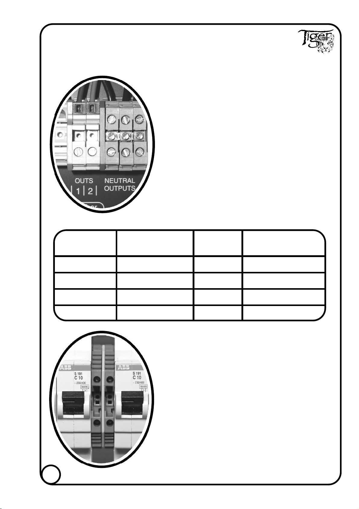
OUTPUT WIRING TP-10-06 (6 CHANNEL)
CHANNEL OUTPUT TERMINALS
6 Live output terminals (10 amp max.).
6 Neutral output terminals (10 amp max.).
One 15 way Earth common bars (10 amp max.).
CONNECTION
Connect loads using wire of between the values stated
below and in accordance with the calculated loadings.
Live, Neutral and Earth wires of the same channel must
pass out through the same coupler.
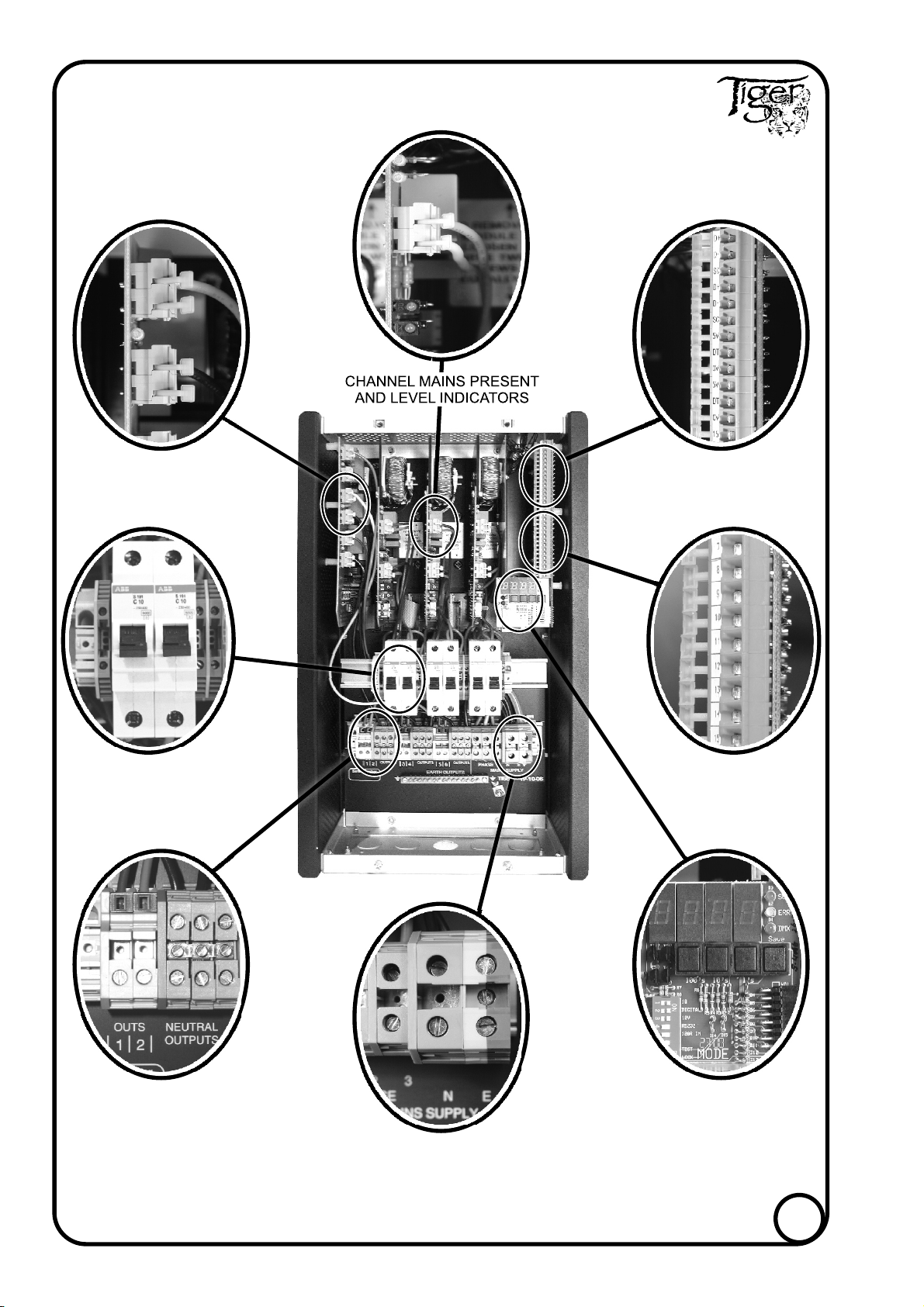
EMERGENCY OUTPUT TERMINALS
Live monitor output terminals for all channels are
located adjacent to the channel MCB's.
These terminals provide a live monitor for emergency
light fittings. If the channel MCB trips the emergency
fittings switch over to battery operation.
CONNECTION
Connect emergency fittings using wire between the
values stated above and in accordance with the
calculated loadings. Live, Neutral and Earth wires of the
same channel must pass out through the same coupler.
NOTE : The emergency current and channel load
current added together should not exceed the maximum
channel current.
TERMINAL SPECIFICATIONS
2
Terminal Wire sizes mm Strip length Tightening torque
Stranded Solid mm Nm lb/in
Live outputs 1 - 61 - 10 12 0.8 - 1.0 7.1 - 8.9
Neutral outputs 1 - 61 - 10 12 0.8 - 1.0 7.1 - 8.9
Earth outputs 1 - 61 - 10 12 0.8 - 1.0 7.1 - 8.9
Emergency outs 1 - 2.5 1 - 2.5 10 0.5 - 0.7 4.4 - 6.2
8