Spezialelektronik GmbH
iseg
Spezialelektronik
GmbH
Email:
sal
[email protected] Phone ++ 49 (0)351 / 26 996 – 0 Bautzner Landstr. 23 http://www.iseg-hv.com Fax ++ 49 (0)351 / 26 996 – 21
6 D - 01454 Radeberg / Rossendorf Germany
2.2 Technical Data and auxiliary information
2.2.1 Device class
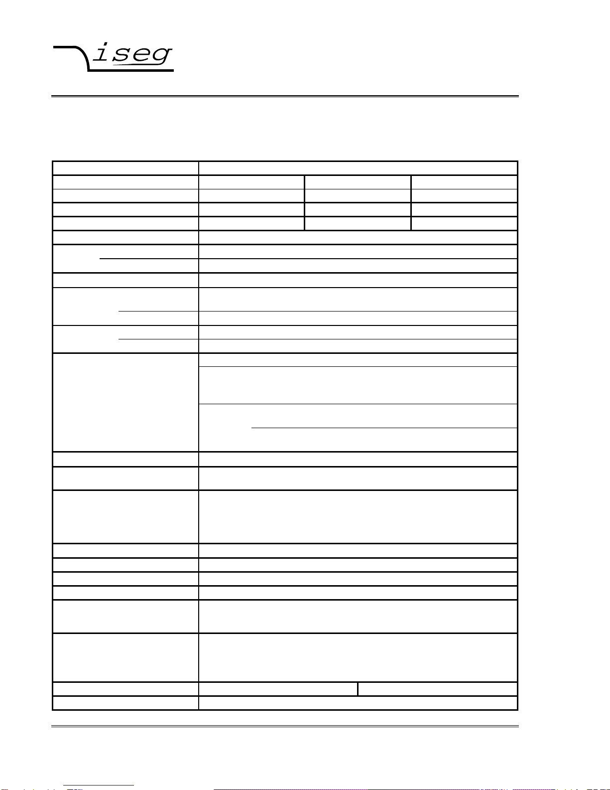
Table 1: Technical Data, Device class
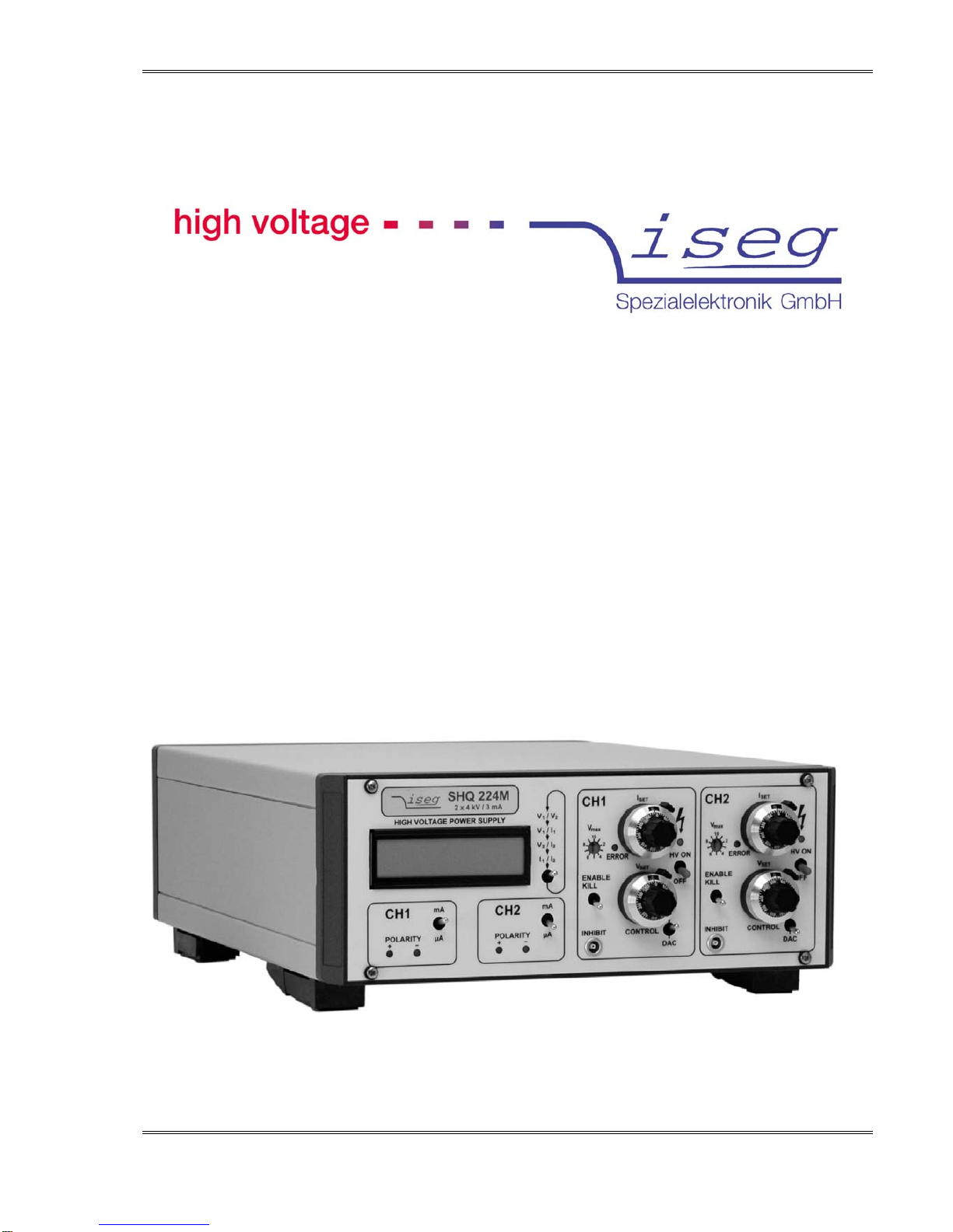
TECHNICAL DATA HIGH PRECISION
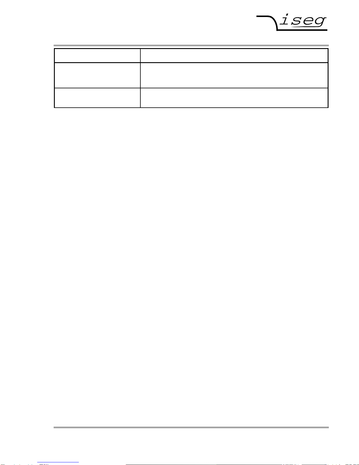
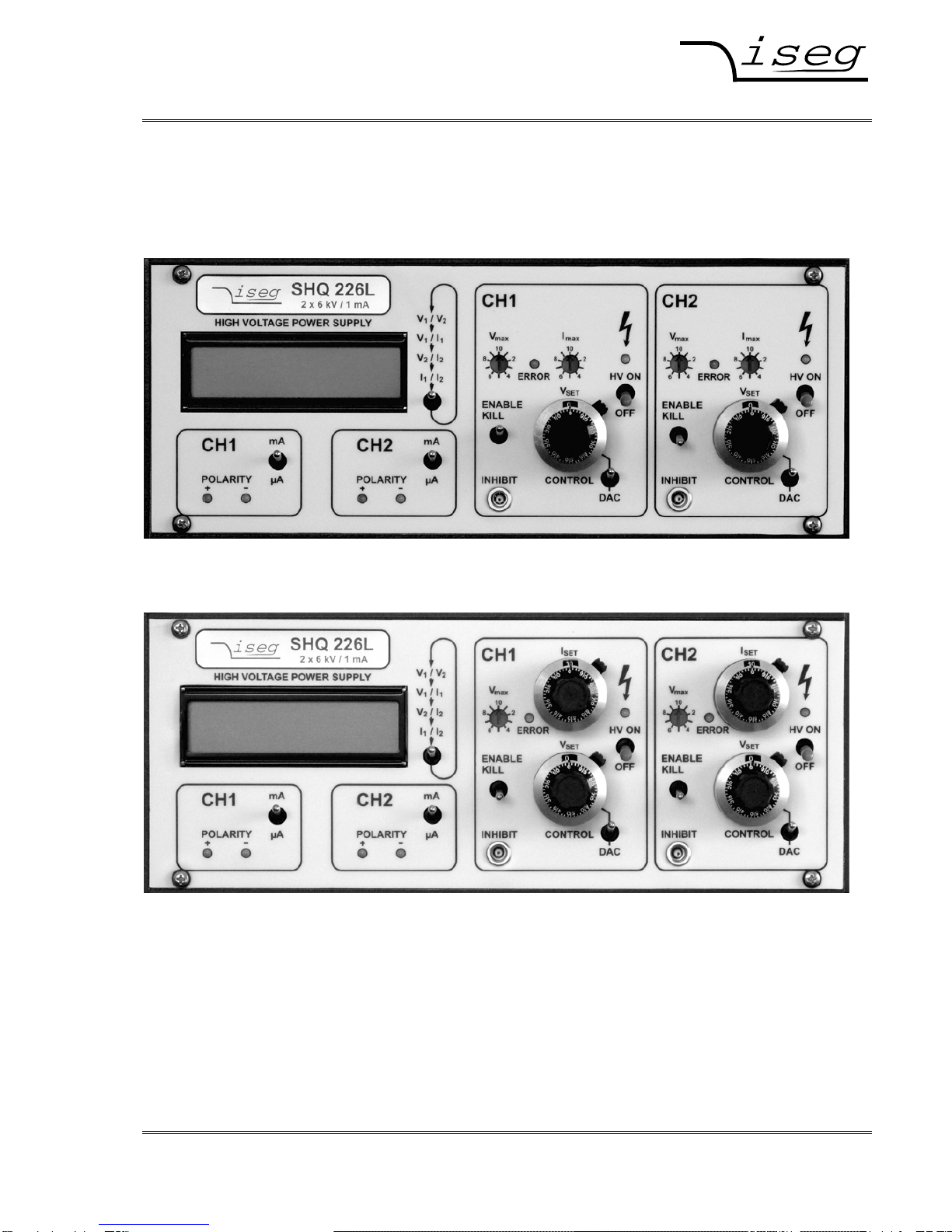
Single channel HV Power Supply SHQ 122 SHQ 124 SHQ 126
Dual channel HV Power Supply SHQ 222 SHQ 224 SHQ 226
Output voltage Vnom 2 kV 4 kV 6 kV
Output current Inom 6 mA 3 mA 1 mA
Ripple and noise typ.: < 2 mVP-P max.: 5 mVP-P
Stability: ∆VO/∆VINPUT < 3 ∗10-5 (after a warm-up period of 30 min)
∆VO (no load/ load) < 5 ∗10-5 (after a warm-up period of 30 min)
Temperature coefficient < 3 ∗10-5/K
Voltage resolution ADC: 100 mV / 6-digit LCD display
(Option VHR: 10 mV for SHQ x22 and x24 only)
measurement accuracy: ±(0,05% VO+ 0,02% Vnom) for one year
Voltage Manual / DAC: 10-turn potentiometer / digital via serial interface
Settings resolution DAC:
100 mV / Option VHR: SHQ x22M with 30 mV; SHQ x24M with 60 mV
Current 2 ranges / 6-digit LCD display
measurement resolution ADC: Range mA: I
nom ≥IO≥100 µA, Resolution: 100 nA
Option 0n1: Inom ≥IO≥10 µA, Resolution: 100 nA
Accuracy: ±(0,1% IO+ 0,02% Inom)
Range µA: 100 µA > IO> 20 nA, Resolution: 1 nA
Accuracy: ±(0,1% IO+ 20 nA)
Option 0n1: 10 µA > IO> 2 nA, Resolution: 100 pA
Accuracy: ±(0,1% IO+ 2 nA)
Value scope data are guaranteed in the range of (1% ∗Vnom) < VO< Vnom for one year
Rate of change of
output voltage fixed: 500 V/s (at HV-ON/OFF)
variable: 2 ... 255V/s (at remote control)
Protection hardware voltage limit (Vmax rotary switch in 10%-steps)
hardware current limit (Imax rotary switch in 10%-steps,
Option IWP: setting with 10-turn potentiometer ISET)
INHIBIT (external signal, TTL, LOW = active)
programmable current trip (serial interface)
Interface RS 232-Interface (Option CAN: CAN-Interface ⇒SHQ x4x)
Line voltage AC (VINPUT) 100 VAC .-. 240 VAC / 0,7 – 0,4 A max / 50 – 60 Hz
Fuse T 1A L 250V / microfuse 5mm x 20mm, 250V / 1AT
Mains connection matching used socket according IEC 60320 C13 (125V/10A or 250V/16A)
Connectors HV output: VO nom rsp. Typ AMP/Tyco SHV-Connector (225059-3)
INHIBIT: VO max 5V 1-pin Lemo-hub (ERN.00.250.CTL)
RS 232 : VO max +/-20V 9-pin female Sub-D connector
Accessories
see Appendix B HV output: Rosenberger SHV coupler 57K101-006N3 assembled on HV cable
INHIBIT: LEMO FFA.00.250.CTA, standard cable 5V
RS 232: custom comercially available RS232 cable, uncrossed, female to
male
Temperature ranges Operating: 0 ... +40 °C Storage: -20 ... +60 °C
Desk case Size (W/H/D) : (236/100/320) mm