Transtechnik ServoPac GDPS User manual
2
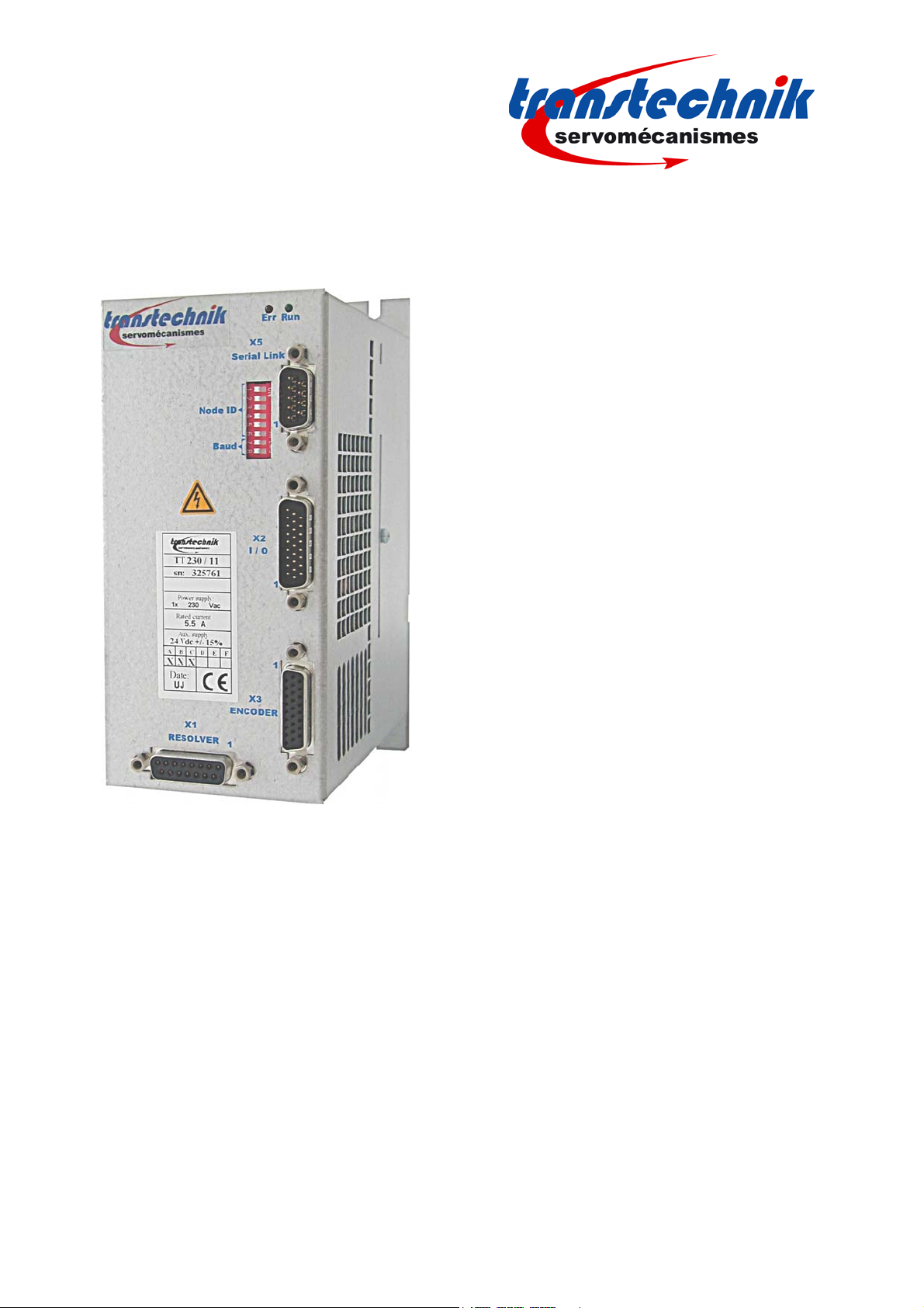
Power supply unit
ServoPac GDPS
2
ServoPac GDPS – Power supply unit
WARNING
This is a general manual describing a series of power supplies having output capability suitable for powering
servo drives.
Instructions for storage, use after storage, commissioning as well as all technical details require the
MANDATORY reading of the manual before getting the drives operational.
Maintenance procedures should be attempted only by highly skilled technicians having good knowledge
of electronics and servo systems with variable speed (EN 60204-1 standard) and using proper test
equipment.
The conformity with the standards and the "CE" approval is only valid if the items are installed according to the
recommendations of the drive manuals. Connections are the user's responsibility if recommendations and
drawings requirements are not met.
TRANSTECHNIK does not assume any responsibility for any physical or material damage due to improper
handling or wrong descriptions of the ordered items.
Any intervention on the items, which is not specified in the manual, will immediately cancel the warranty.
TRANSTECHNIK reserves the right to change any information contained in this manual without notice.
©TRANSTECHNIK, May 2011. All rights reserved.
Issue : 2.2
CAUTION
Any contact with electrical parts, even after power down, may involve physical damage.
Wait for at least 10 minutes after power down before handling the devices (a residual voltage
of several hundreds of volts ma
y
remain durin
g
a few minutes
)
.
ESD INFORMATION (ElectroStatic Discharge)
TRANSTECHNIK drives are conceived to be best protected against electrostatic discharges.
However, some components are particularly sensitive and may be damaged if the drives are not
properly stored and handled.
STORAGE
- The devices must be stored in their original package.
- When taken out of their package, they must be stored positioned on one of their flat
metal surfaces and on a dissipating or electrostatically neutral support.
- Avoid any contact between the device connectors and material with electrostatic
potential (plastic film, polyester, carpet …).
HANDLING
- If no protection equipment is available (dissipating shoes or bracelets), the devices must
be handled via their metal housing.
- Never get in contact with the connectors.
ELIMINATION
In order to comply with the 2002/96/EC directive of the European Parliament and of the Council of
27 January 2003 on waste electrical and electronic equipment (WEEE), all TRANSTECHNIK
devices have got a sticker symbolizing a crossed-out wheel dustbin as shown in Appendix IV of
the 2002/96/EC Directive.
This symbol indicates that TRANSTECHNIK devices must be eliminated by selective disposal and
not with standard waste.

3
Content
ServoPac GDPS – Power supply unit
Content
Page
CONTENT ............................................................................................................................................... 2
CHAPTER 1 - SPECIFICATIONS........................................................................................................... 3
1.1– INTRODUCTION......................................................................................................................... 3
1.2 –ORDERING CODE..................................................................................................................... 3
1.2.1 – ServoPac GDPS power supply unit.................................................................................... 3
1.2.2 – Accessories......................................................................................................................... 3
1.3 –MAIN TECHNICAL DATA........................................................................................................... 4
1.4 –MECHANICAL DIMENSIONS..................................................................................................... 5
1.5 –SIZING OF THE POWER SUPPLY ............................................................................................ 6
1.5.1 – Continuous power............................................................................................................... 6
1.5.2 – Braking system ................................................................................................................... 7
CHAPTER 2 – INPUTS - OUTPUTS ...................................................................................................... 9
2.1 –X1 CONNECTOR: POWER CONNECTOR................................................................................ 9
2.2 –X2 CONNECTOR: AUXILIARY POWER SUPPLY AND AOK CONNECTOR............................ 9
2.3 –LEDS ........................................................................................................................................ 10
2.4 –SW1 MINISWITCH...................................................................................................................10
CHAPTER 3 – CONNECTION.............................................................................................................. 11
3.1 –CONNECTION DIAGRAM........................................................................................................ 11
3.2 –FUSE RATING.......................................................................................................................... 11
CHAPTER 4 – TROUBLESHOOTING ................................................................................................. 12
4.1 –UNDERVOLTAGE FAULT........................................................................................................ 12
4.2 –OVERVOLTAGE FAULT.......................................................................................................... 12
4.3 –BRAKING TRANSISTOR FAULT............................................................................................. 12
4.4 –CONFIGURATION FAULT....................................................................................................... 12
4 Chapter 1 - Specifications
ServoPac GDPS – Power supply unit
Chapter 1 - Specifications
1.1– INTRODUCTION
The external ServoPac GDPS-400/xx power supply unit is the multi-axis power supply intended for use with the
ServoPac TT actuators. For the various configurations, see ServoPac TT Installation manual.
NOTE
The ServoPac GDPS -400/xx power supply unit operates within a wide voltage range between 230 and 480 VAC.
Consequently, the output power will depend on the input voltage.
The specified power values are given for a maximum voltage of 480 VAC.
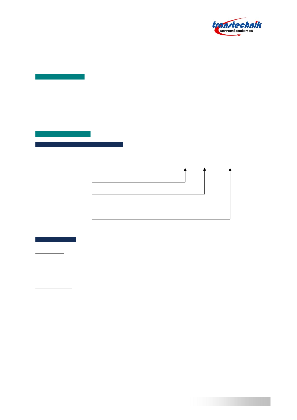
1.2 – ORDERING CODE
1.2.1 –SERVOPAC GDPS POWER SUPPLY UNIT
1.2.2 –ACCESSORIES
Connector kit
FC-GDPS
This connector set includes power (X1) and auxiliary (X2) connectors.
Braking resistors
The choice of the braking resistor should be the result of the method described in Chapter 1.5.2: Braking system.
However, the following references are recommended in most applications:
- dp 16.5/560 to be connected to a GDPS 400/32
- dp 33/280 to be connected to a GDPS 400/16.
Voltage: 400 VAC
Rated power: 16 or 32 kW
ServoPac GDPS – 400 / pp - xx
xx: Delivered with or without power connector
00: Without connector set
FC: With power (X1) + auxiliary (X2) connector set

5
ServoPac GDPS – Power supply unit
Chapter 1 - Specifications
1.3 – MAIN TECHNICAL DATA
Operating voltage
400 V
A
COperating voltage
230 VAC
Mains operating voltage 400 - 480 VAC +10%/-15%* 230 VAC +10%/-15%
Mains specifications three-phase, 50 to 60 Hz,
TN or TT system with grounded neutral point.
IT system supported but not recommended
(phase-ground voltage must be balanced)
Voltage unbalance Max. 3 % of the mains voltage fundamental
Mains filter integrated
Peak output power GDPS 16 kW
GDPS 32 kW 45 kW
90 kW 25 kW
45 kW
Rated output power GDPS 16 kW
GDPS 32 kW 16 kW
32 kW 8 kW
16 kW
Static output DC voltage VDC =
√
2
×
VAC VDC = √2 ×VAC
Dynamic output DC voltage according to the mains
voltage / regenerative phase 480 - 800 VDC 275 - 400 VDC
Triggering threshold of the braking system 790 V
±
5% 390 V ±5%
Minimum braking resistor value GDPS 16 kW
GDPS 32 kW 33
Ω
16.5 Ω16.5 Ω
7.5 Ω
Peak power of the braking system GDPS 16 kW
GDPS 32 kW 20 kW
40 kW 10 kW
20 kW
Maximum continuous power of the
braking system (I²t limited) GDPS 16 kW
GDPS 32 kW 4 kW
8 kW 2 kW
4 kW
Undervoltage threshold 200V
±
5% 100V ±5%
Overvoltage threshold 950V
±
5% 450V ±5%
Maximum surrounding air temperature - operation: +5°C to +50°C (from 40°C, the rated power
must be reduced by 3 % per additional °C)
- storage: -20°C to +70°C.
* For special applications, the input voltage range can be extended to 230 Vac - 480 Vac (see chapter 2.4 for
reducing the undervoltage threshold to 100 Vdc).
6
ServoPac GDPS – Power supply unit
Chapter 1
-
Specifications
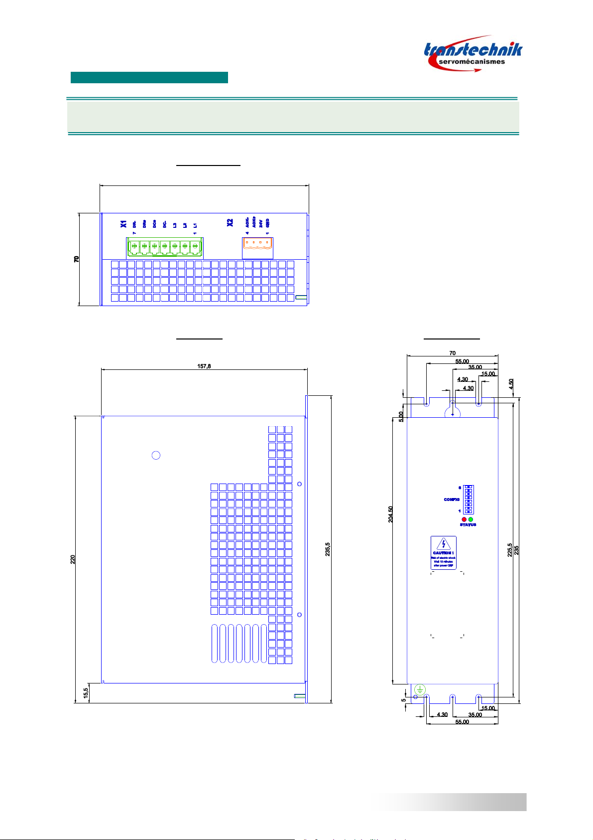
1.4 – MECHANICAL DIMENSIONS
BOTTOM VIEW
SIDE VIEW FRONTVIEW
Dimensions are given in mm.
157,8
VERTICAL MOUNTING IS MANDATORY

7
Chapter 1 - Specifications
ServoPac GDPS – Power supply unit
1.5 – SIZING OF THE POWER SUPPLY
1.5.1 –CONTINUOUS POWER
For a reliable and safe operation of the installation, the continuous average power needs to be evaluated for all
axes.
Various ways to proceed for evaluating the continuous power of a machine are listed below:
Accurate method:
The power can be calculated by the absolute value average of the mechanical power for each axis.
∑><= N
naxismechanicalGDPSaverage PAbsP 1... )(
Example for one axis:
)45.(4.
2
1
)34.(3.
2
1
)23.(2.
2
1
)12.(1.
2
1
.
ωωωωωωωω
−+−+−+−= TTTTP GDPSaverage
With: T: Torque value in Nm (positive when the speed increases)
ω: Speed value in rad/s
Simplified method 1:
If the continuous average power cannot be evaluated by the "accurate method", it may be convenient to use the
power of the application motors.
The electrical power can be evaluated by the mechanical power divided by the electromechanical efficiency.
If motors have been correctly sized, the average power can be evaluated by means of the following formula:
∑
=N
N
nmotorrated
GDPSaverage P
P1..
.
η
With 9.0
≈
η
Simplified method 2:
If the continuous average power cannot be evaluated by the "accurate method", it may be convenient to define a
service ratio (KS) for each drive.
In this case, the average power can be evaluated by means of following formula:
∑×= N
naxisratedSGDPSaverage PKP 1...
With: 4.0≥
S
K
naxisratednaxisrated IUP .... 3××=
Speed
Torque
abs(Power) Average
ω1
ω2
ω4
ω5
T1
T2 T3
T4
ω3

8
ServoPac GDPS – Power supply unit
Chapter 1 - Specifications
1.5.2 –BRAKING SYSTEM
The braking I²t function defines the conduction time of the braking transistor over 1 second horizon time.
Two different quantities are necessary to completely define an application:
- The peak power:
oIt defines the deceleration energy,
oIt is limited by the braking transistor current.
- The average power:
oIt defines the heat dissipation
Method for the design of the braking system:
1. Estimation of the regenerative power
The regenerative power must be calculated for each deceleration phase of each motor.
JOULEMOTORELEC
MOTORMOTORJOULE
COUPLINGLOADMOTOR
LOAD
DEC
TOTAL
LOAD
PPP
IRP
PP
nnT
tnnJ
P
−=
=
=
+
−
−
=
2
21
2
2
2
1
.
2
3
.
19 ).(
.180 ).(
η
With : PLOAD: Power regenerated by the load during the deceleration phase in W
JTOTAL: Motor + load inertia of the axis reflected to the motor shaft in kg.m²
n1: Rotation speed at the beginning of the deceleration phase in RPM
n2: Rotation speed at the end of the deceleration phase in RPM
tDEC: Deceleration time in s
TLOAD: Torque applied by the load on the motor shaft at the beginning of the deceleration phase in Nm
PMOTOR: Power regenerated on the motor shaft in W
ηCOUPLING: Efficiency of the mechanical coupling (gearbox). If no gearbox is used ηCOUPLING ≈1
PJOULE: Losses in the motor windings in W
RMOTOR: Winding resistance measured between two phases of the motor in Ω
IMOTOR: Average current in one phase of the motor during the deceleration phase in A
PELEC: Average power managed by the drive during the deceleration phase in W
2. Choice of the ohmic value
ELEC
BRAKING
BRAKINGMIN P
U
RR ˆ
.2
2
<≤
With: RMIN: Minimum braking resistor value in Ohm according to section "Main technical data".
UBRAKING: Triggering threshold of the braking system in V.
R
BRAKING: Braking resistor in Ω.
ELEC
P
ˆ: Maximum of all PELEC calculated for all motors and for all deceleration phases in W.
3. Average power
The required average power must be calculated to correctly choose the size of the braking resistor and to take
into account the heat dissipation effect into the near environment.
CYCLE
DEC
PN
ELEC
AVERAGE T
pnTpnP
P),(),(
,
1,1 ×
=∑
With: PELEC: Power managed by the drive axis n during the deceleration phase p in W
4. Braking I²t setup
BRAKING
BRAKINGON
tI R
Ut
P2
².
1000
=
With: PI²t: Maximum average power allowed by the braking I²t function in W
tON: Conduction time allowed by the braking I²t function in ms
UBRAKING: Triggering threshold of the braking system in V
R
BRAKING: Braking resistor in Ω.

8
ServoPac GDPS – Power supply unit
Chapter 1 - Specifications
5. Connection of the braking resistor
In order to avoid any EMC or electrical problem, some rules must be observed:
•heat must be evacuated,
•shielded cable or at least twisted wires must be used,
•wires must bear high voltage and high temperature (recommended type: UL1015, AWG 14)
•wires must be as short as possible (max. 1 m).
The braking resistor MUST be mounted out of range of heat sensitive and
inflammable elements (plastic, cable sleeves, etc.).

9
Cha
p
ter 2
-
In
p
u
t
s
-
Out
p
ut
s
ServoPac GDPS – Power supply unit
Chapter 2 – Inputs - Outputs
2.1 – X1 CONNECTOR: POWER CONNECTOR
Manufacturer: Phoenix contact
Type: PC 5/ 7-G-7.62
Reference: 1720518
Tightening torque: 0.7 to 0.8 Nm
PIN SIGNAL I/O FUNCTION DESCRIPTION
1 L1 I Mains input supply Integrated EMI filter.
Grounding by means of a screw with nut on the
bottom plate.
2 L2 I
3 L3 I
4 DC- I/O DC bus negative voltage output Output to power drives.
Recommended wire section:
- 10 mm² or AWG8 for GDPS 32 kW
- 4 mm² or AWG12 for GDPS 16 kW
Maximum length: 200 mm
5 DC+ I/O DC bus positive voltage output
6 DR+ O Braking resistor connection Recommended wire section: 2.5 mm² or AWG14.
Braking resistor is required.
7 DR- O
2.2 – X2 CONNECTOR: AUXILIARY POWER SUPPLY AND AOK CONNECTOR
Manufacturer: Weidmuller
Type: BLZ 5.08 / 4B
Reference: 152896
Tightening torque: 0.4 to 0.5 Nm
PIN SIGNAL I/O FUNCTION DESCRIPTION
1 0V = GND I Mains isolated 24 Vdc auxiliary
supply
0 V input referenced to the GND
potential of the amplifier housing
24 Vdc supply: +/- 10%
Consumption: 0.320 A
2 24 V I
3 AOK+
O Shut down the mains in case of
power component failure OptoMos relay: high output impedance if fault
Umax = 50 V , Imax = 300 mA
Polarity must be observed:
AOK+ = positive potential
AOK- = negative potential
4 AOK- O
The DC+/DC- polarity between the multiaxis power supply unit and the drives MUST be observed.
10
ServoPac GDPS – Power supply unit
Cha
p
ter 2
-
In
p
uts
-
Out
p
ut
s
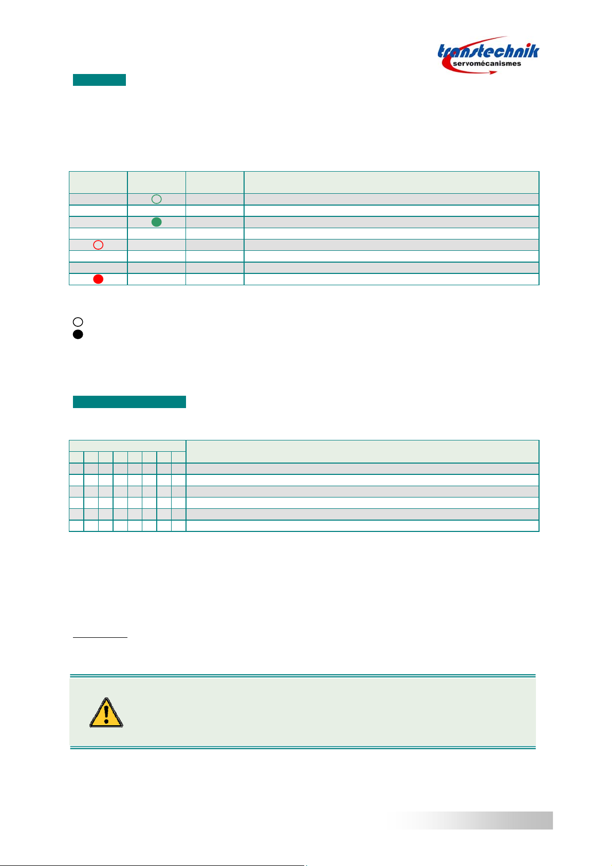
2.3 – LEDS
The ServoPac GDPS unit cannot be reset.
If a fault has been detected, the user has to identify the origin of the problem.
Once the origin of the problem solved, the auxiliary power supply of the ServoPac GDPS unit has to be switched
off/on.
LEDs available on the front panel are used to display the ServoPac GDPS unit status:
RED
LED GREEN
LED AOK DESCRIPTION
XOPEN +24 VDC auxiliary power supply is off
X— — Power supply is off: undervoltage fault
XPower supply is on
X CLOSE No fault detected
- - X OPEN Overvoltage fault
- - - - X OPEN Braking transistor fault
X OPEN Configuration fault
Legend:
X No influence on the status described
LED is off
LED is on
— — regular blink
- - one flash
- - - - two flashes
2.4 – SW1 MINISWITCH
The miniswitch available on the front panel is used to configure the operation mode of the ServoPac GDPS unit:
MINISWITCH DESCRIPTION
1 2 3 4 5 6 7 8
0 0 0 0 X X X XOperating voltage = 400 VAC (default configuration)
1 1 0 0 X X X XOperating voltage = 400 VAC with undervoltage threshold reduced to 100VDC
1 1 1 1 X X X XOperating voltage = 230 VAC
X X X X 0 0 0 0 Braking I²t = 200 ms (default configuration)
X X X X 1 1 1 1 Braking I²t = 100 ms
The configuration of the ServoPac GDPS unit is read only at power up.
If the configuration has to be changed, proceed as described below:
1. Switch off all power supplies (mains and auxiliary power supplies)
2. Change the miniswitch code
3. Switch on the auxiliary power supply
4. Verify that no configuration fault is detected.
IMPORTANT:
When the operating voltage is 230 V, make sure that it is correctly set up in the ServoPac GDPS power supply
unit AND in the drive.
RISK OF ELECTRIC SHOC
K
The TT GDPS unit is IP20 classified. Since the miniswitch configuration requires a little
screwdriver, the SW1 miniswitch must always be handled with power off.

11
Cha
p
ter 3
-
C
onnection
ServoPac GDPS – Power supply unit
Chapter 3 – Connection
3.1 – CONNECTION DIAGRAM
3 x400Vac
Q1: Circuit breaker type D
I1s = 10 x In
GDPS16 = 20 A
GDPS32 = 40 A
F1: Optional fuse / mandatory for UL
KM1: Mains contactor
DC+
DC-
TT GDPS-400/xx
X2 X1
12341234567 DC+
DC-
Q1
AXIS 1 AXIS N
TT drive TT drive
Braking
resistor
AC 24V
isolated
-
+
230 V
0 V
24 V
AOK+
AOK-
L1
L2
L3
DC-
DC+
DR+
DR-
Power
ON
Power relay
remote control
KM1
24 V
AOK GDPS
+
+
+
-
-
-
AOK AXIS 1
AOK AXIS N
STOP
km1
KM1
F1
3.2 – FUSE RATING
For the ServoPac GDPS-400/xx multi-axis power supply unit:
ServoPac GDPS 400/16 400/32
FERRAZ A60Q20-2 A60Q40-2
Polarity DC+ and DC- between drives and the TT GDPS power supply unit must be observed.
Otherwise, drives will be immediately destroyed.
AOK input must be wired in order to reduce the risk of fire.
12
ServoPac GDPS – Power supply unit
Cha
p
ter 4
-
Troubleshootin
g
Chapter 4 – Troubleshooting
4.1 – UNDERVOLTAGE FAULT
When switching on the auxiliary 24 VDC supply, the ServoPac GDPS unit always displays the undervoltage fault.
The undervoltage fault will go out when switching on the power voltage, after a few seconds time delay that
corresponds to the soft start of the power capacitors.
The soft start system will be activated again when the voltage will drop below the undervoltage threshold.
If the fault display remains after switching on the power supply:
- Check that the power supply is actually on and the actual voltage value. The DC bus voltage value can
be measured by mean of the digitizing oscilloscope.
4.2 – OVERVOLTAGE FAULT
The overvoltage fault is used to protect the drive against high voltage values on the DC bus.
This fault can have different origins:
- Check that the braking resistor is not open.
- Check that the operating voltage is correctly set up according to the mains voltage (SW1 configuration).
- When the braking I²t protection becomes active, it prevents the braking resistor from switching.
Check that the braking ability is sufficient for the application.
In this case, a lower ohmic value may solve the problem.
4.3 – BRAKING TRANSISTOR FAULT
The braking transistor fault is used to protect the ServoPac GDPS unit and the braking resistor against a short
circuited transistor.
This fault can have two different origins:
- If no braking resistor is connected, the fault will be displayed.
Check that a braking resistor is connected and not opened.
- Else the braking transistor has been destroyed. In this case, the ServoPac GDPS unit must be repaired.
4.4 – CONFIGURATION FAULT
The configuration fault is used to prevent a wrong configuration by means of the SW1 miniswitch.
- Check the SW1 miniswitch code in the table.
Attention: The opening of the branch-circuit protective device may be an indication that a fault
has been interrupted. To reduce the risk of fire or electric shock, current-carrying parts and
other components of the controller should be examined.
Table of contents


