Modell-zug elektronix Z83/84 User manual

Page 1
All brand names, product names, and logos are the property of their respective owners or companies.
Copyright © 2006 by Modell-Zug Elektronix.
Decoder Z83/84
1. Introduction
hank you for purchasing this Modell-Zug Elektronix product. he Decoder Z83/84 was specifically designed as an
all-in-one digital accessory decoder to provide maximum versatility in the control of model railroad accessories.
Each of the decoder’s four channels contain both momentary pulse outputs for controlling signal or turnout
solenoids and continuous switched outputs for supplying power to sidings, lighting circuits, or other accessories. In
this way, each independent channel of the decoder may be used in any one of three modes: Switch only, Pulse only,
or Switch & Pulse. his allows for various combinations of output types to fit the specific needs of a given layout
area without requiring multiple decoder types. And, since the Decoder Z83/84 utilizes the industry standard
Motorola digital data format, it is compatible and interchangeable with products from major manufacturers such as
Märklin, Uhlenbrock, Viessmann and others. Please study the following manual in its entirety to gain full utility and
enjoyment from this Modell-Zug Elektronix product.
2. Overview of Features
Mechanical Specifications
Dimensions: W 5.37 in.; D 2.63 in.; H 1.26 in. (inc. mounting flanges)
Weight: 5 oz.
Electrical Specifications
Power Consumption: 0.1W typ.; (1W max. w/Pulse Output active)
Input Voltage Range: ±22V typ. (±28V max.)
Input Data ype: 9600 bps (Motorola rinary Data Format)
“Switch” Output Ratings: 2A max.; 30V max.
“Pulse” Output Ratings: 1.2A typ. (1.5A max.); 19V typ. (20V max.)
Durable External
Mounting Points
Rugged ABS
Enclosure
Compatible with
Motorola Digital
Data Format
Continuous
Switched
Outputs
Momentar
Pulse
Outputs
Universal
Terminal
Connections
Decoder
Z
83/84
Made in U.S.A.
Modell-Zug
Elektronix
Pulse 4
Pulse 3
Switch 4
Switch 3
TRK
Pulse
Switch
Switch 2
Pulse 2
TRK

Page 2
www.modell-zug.com
3. Operating the Decoder Z 3/ 4
3.1 Setting the Digital Address of the Decoder
A unique Digital Address identifies each decoder in the digital system. his allows the central unit to broadcast an
entire set of digital commands to all decoders in the system, and for each decoder to execute only those commands
that match its own internal Digital Address. By default, the Digital Address of each Z83/84 decoder is set to “01”,
and must be changed if your application requires more than one decoder. It is not recommended to configure two
decoders to the same Digital Address, as it may cause excessive electrical loading of the Central Unit or Booster.
For these reasons, it is important that each decoder is set to its own unique address. he Digital Address of the
Z83/84 may be changed by resetting the eight coding switches located inside the decoder housing, as outlined in the
following procedure.
1. Remove the top cover of the decoder housing, which is held in place by four cross-head screws.
2. Once the top cover has been removed, the switchblock is located on the lefthand side of the decoder board as
shown in Figure 1 below.
3. Set the coding switches 1-8 in accordance with the settings listed in Table 1 below to achieve the desired Digital
Address. he Digital Address code is listed in the lefthand column; the righthand column contains the numbers
of the switches that are turned ON for that address. (Note: small flat-blade jewelers/hobby screwdriver works
well to slide the switches.):
01 -23-5-7- 17
-----67- 33
1---5--8 49 -2-4---8
02 --3-5-7- 18
1-3---7- 34
-2--5--8 50 ---4---8
03 1--45-7- 19
-23---7- 35
----5--8 51 1------8
04 -2-45-7- 20
--3---7- 36
1-3--6-8 52 -2-----8
05 ---45-7- 21
1--4--7- 37
-23--6-8 53 -------8
06 1---5-7- 22
-2-4--7- 38
--3--6-8 54 1-3-5---
07 -2--5-7- 23
---4--7- 39
1--4-6-8 55 -23-5---
08 ----5-7- 24
1-----7- 40
-2-4-6-8 56 --3-5---
09 1-3--67- 25
-2----7- 41
---4-6-8 57 1--45---
10 -23--67- 26
------7- 42
1----6-8 58 -2-45---
11 --3--67- 27
1-3-5--8 43
-2---6-8 59 ---45---
12 1--4-67- 28
-23-5--8 44
-----6-8 60 1---5---
13 -2-4-67- 29
--3-5--8 45
1-3----8 61 -2--5---
14 ---4-67- 30
1--45--8 46
-23----8 62 ----5---
15 1----67- 31
-2-45--8 47
--3----8 63 1-3--6--
16 -2----67- 32
---45--8 48
1--4---8 64 -23--6--
Table 1. Digital Address Switch Settings
Coding Switches:
Switchblock Location:
ON
1
2
3
4
5
6
7
8
9
10
11
12
Digital Address
Mode
Figure 1. Address & Mode Coding Switches
Cover Alignment Mark !
MZE

Page 3
www.modell-zug.com
3.2 Setting the Output Mode of the Decoder Channels
Each channel of the Z83/84 decoder contains both momentary pulse and continuous switched output types. Although
certain applications may require both output types of a given channel to be activated simultaneously, many basic
applications will not. For this reason, each of the Switch outputs of the Z83/84 decoder may be individually enabled
or disabled. his is made possible by the four Output Mode coding switches located inside the decoder. By default,
all of these switches are set to “enabled.” If your application does not require the Switch output of a given channel, it
is recommended that you disable it to avoid the unnecessary relay “click” when this channel is activated. (Note that
the Pulse outputs of all channels remain enabled regardless of the Output Mode switch settings, but will not conduct
electrical current unless a solenoid or relay is connected to them.) he Output Mode of each channel may be
changed by following the procedure below:
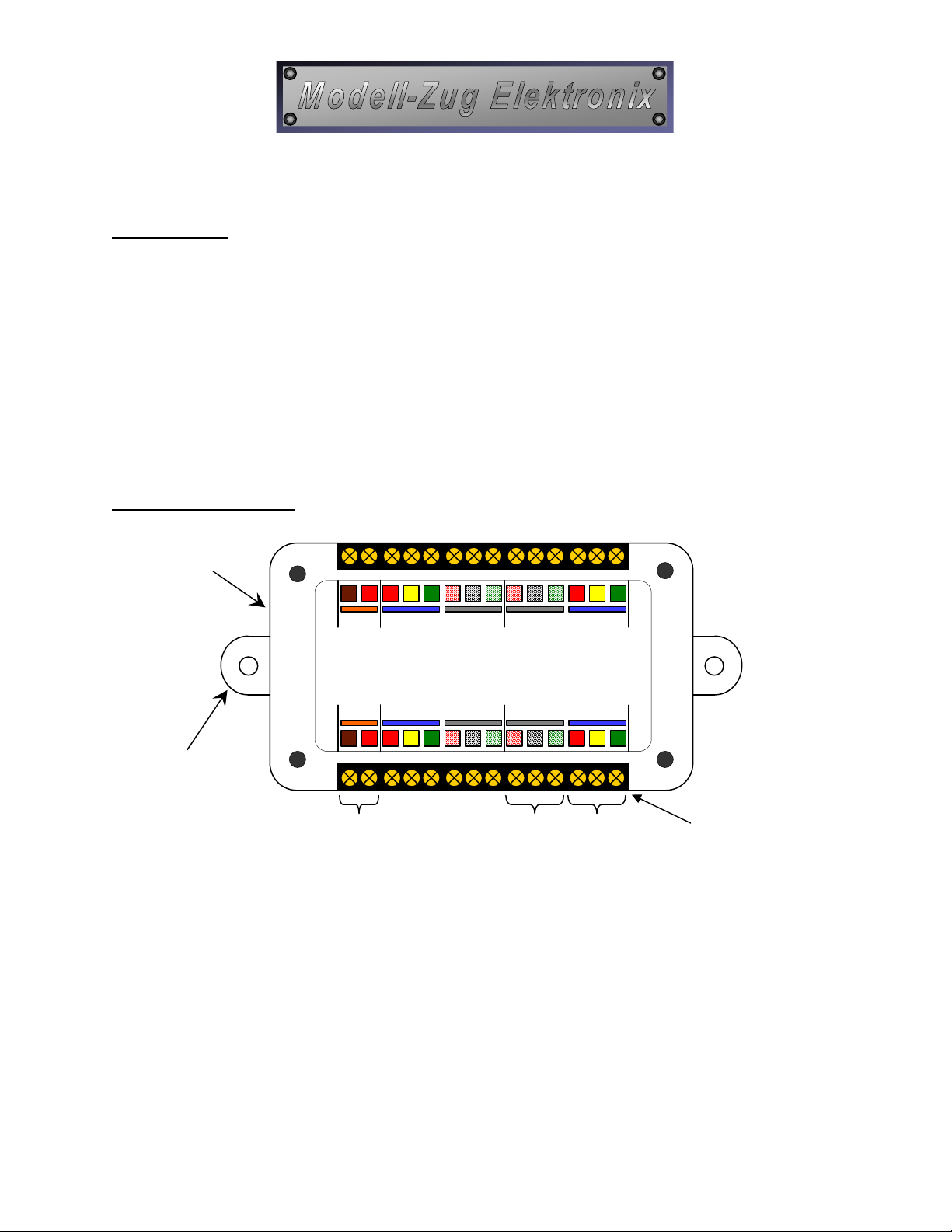
1. With the top cover removed, the Output Mode coding switches are located on the lefthand side of the decoder
board (see Figure 1 above).
2. Switches 9-12 of the switchblock control the output modes of each channel in the decoder. o enable the Switch
output of a given channel, the corresponding code switch must be set to “ON” as shown in Table 2 below:
Code
Switch ON O
9 “Switch 4” Enabled “Switch 4” Disabled
10 “Switch 3” Enabled “Switch 3” Disabled
11 “Switch 2” Enabled “Switch 2” Disabled
12 “Switch 1” Enabled “Switch 1” Disabled
3. Once you have set the Output Mode switches, reinstall the top cover of the housing and the four cross-head
screws. IMPORTANT: Be sure to orient the top cover as in Figure 1 so that the Orange connections
marked “TRK” on the cover are a igned with the Orange marks on the termina s inside the decoder!!!
3.3 Installing & Connecting the Decoder
All of the connections on the Decoder Z83/84 utilize setscrew-style terminal blocks to allow for universal
compatibility without special connectors. hese terminals will accept stripped or stripped & tinned wire of any
gauge from 24 to 14 AWG. Each connection point is color-coded and clearly labeled on the top cover to make
connections easier, even when the decoder is being installed under the layout. Several decoders can be connected to
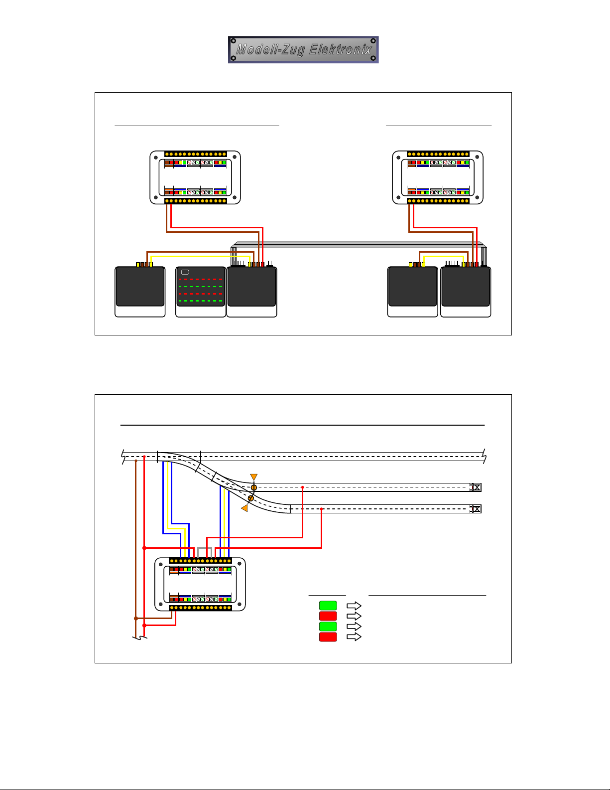
the digital system in series, or “bussed,” through the two sets of TRK connections on each decoder. urnout
solenoids, signal solenoids, and remote relays may be connected to the blue Pulse group of outputs. IMPOR AN :
Do not connect multiple turnout solenoids to one Pulse output, as it will overload the Central Unit or Booster. rack
sidings, lighting, or motorized accessories are connected to the grey Switch outputs. Various types of connections
are illustrated in the diagrams and procedure that follow:
1. Be sure that all power to the layout is completely switched OFF before installing or making any connections to
the decoder or any other piece of equipment.
2. Install the decoder in the desired location by drilling two small holes under the layout and mounting the decoder
using wood screws through the decoder’s two external mounting points.
3. Once the decoder has been installed, refer to the following diagrams in Figures 2-5 to find suggestions and
examples of connections to match your application. (Note: he diagrams assume Decoder Address “01”.)
4. Before making any connections, wires should be carefully stripped to avoid damage to the conductors and the
stripped end then retwisted to prevent splayed wire ends. Solder-tinning is also recommended.
5. Once all of the wires have been connected, double-check all connections for possible short-circuits, poor
connections, or misconnections before turning on the layout power. If your application has switched track
sidings powered by Boosters, be sure that these sidings contain appropriate pickup shoe lifters at the insulation
point to prevent a short-circuit between different digital circuits (Booster and Central Unit).
6. Switch on the power and check that all accessories function correctly.
7. Enjoy operating your accessories digitally with the Modell-Zug Elektronix Decoder Z83/84!
Table 2. Output Mode Switch Settings
MZE
MZE

Page 4
www.modell-zug.com
Central Unit
Transformer
Keyboard
OR:
Control Unit
Central Control-I
Intellibox
Decoder Z83/84
Decoder Z83/84
Booster
Transformer
Connection to Central Unit:
Connection to Booster:
Figure 2. Connections to the Digital System
Connection to Turnouts & Sidings:
4
4
3
3
W1 Straight; G1/G2 Power O
W1 Curve; G1/G2 Power ON
W2 Straight; G1 O , G2 ON
W2 Curve; G1 ON, G2 O
Keyboard:
Action:
W1
W2
G1
G2
Decoder Z83/84
(From Central Unit)
Figure 3. Connections in a Station/Yard Area (Simultaneous Turnout & Siding Control)

Page 5
www.modell-zug.com
Connection to Signals & Uncou ler Tracks:
Keyboard:
Action:
4
4
2
3
2
V1&H1 Orange
V1&H
1 Red
V1&H1 Green
U1 Activate
U2 Activate
V1
H1
U1
U2
Decoder Z83/84
(From Central Unit)
Optional 1.5k
Ω
ΩΩ
Ω
Resistor
Figure 4. Connections to Solenoid-Driven Accessories

Page 6
www.modell-zug.com
Connection to AC & DC Motors:
Keyboard:
Action:
2
2
4
3
4
3
1
1
M1 orward
M1 Reverse
M2 orward
M2 Reverse
M3
orward
M3 Reverse
Decoder Z83/84
Transformer
4 x 1N4001
Diode
2 x 1N4001
Diode
AC Motor
(app. 17VAC)
M2
(From Central Unit)
DC Motor
(app. 7VDC)
M3
DC Motor
(app. 14VDC)
M1
Figure 5. Connections to Motorized Accessories