VNS G116 User manual
G116 User Guide Document: G116-1
--------------------------------------------------------------------------------------------------------------------------------------------
0
G116 warping box User Guide
Version: 2.0
Website: www.vnstw.com
The absolute opposite of ordinary
Input: up to 7680*2160 @30Hz, 5760*1200 @60Hz, 4096*2160 @60Hz
4:4:4 full color sampling
Output: up to 1920*1200 @60Hz, 2048*1080 @60Hz
•Single channel
•Image warp & geometry alignment
•Edge mask
•PIP/POP
•Image rotation and flip
•Image anyplace cropping
with matrix SW function

G116 User Guide Document: G116-1
--------------------------------------------------------------------------------------------------------------------------------------------
1
Table of Contents
Disclaimer/Copyright Statement.......................................................................................................... 2
Warranty/RMA………………………………………………………………………………………………… 2
FCC/CE Statement............................................................................................................................... 2
Introduction……………………………………………………………....................................................... 3
Functions and Features....................................................................................................................... 4
1. Content in the packing box............................................................................................................ 6
2. Basic operation & settings
2.1. Connecting the Input and output…………………………………….…..................................... 6
2.2. LED indicators………….....................................................…………....................................... 7
2.3. System Connection and Power On.......…………………………………………………………… 8
2.4. System Settings: Box ID, RS232, Ethernet............................................................................. 8
2.5. How to use IR Remote Controller........................................................................................... 10
2.6. Full screen and native aspect ratio………………………………………………………………… 11
2.7. Image rotation and flip………………………………………………………………………………. 11
2.8. Color adjustment…………………………………………………………………………………… 12
2.9. OSD Lock and unlock……………………………………………………………………………… 12
2.10. System synchronization…………………………………………………………………………… 13
2.11. PIP/POP-- Dual window display (Picture in picture & side by side) …………………………. 13
3. Geometry Alignment
3.1. Select the right Grid Pattern for geometry alignment……………………………………………. 16
3.2. Grid pattern pixel size selection……………………………………………………………………. 17
3.3. Geometry alignment………………………………………………………………………………… 17
3.3.1.Geometry alignment through remote controller……………………………………………. 18
3.3.2. [2x2] 4 corner geometry alignment…………………………………………………………… 18
3.3.3. [3x3], [5x3], [9x5] warp alignment……………………………………………………………. 18
3.3.4. Linearity grid line adjustment…………………………………………………………………. 19
3.3.5. Corner [Wall] geometry adjustment…………………………………………………………… 20
4. [Video Wall] settings………………………………………………………………………………………. 22
4.1. [Zoom]: split the signal source……………………………………………………………………… 22
4.2. [Pan]: assign image location………………………………………………………………………… 23
4.3. [Overlap]: crop the right image for each projector………………………………………………… 23
4.4. [Position]: shift image position without changing image size……………………………………. 23
5. [Edge Mask] ………………………………………………………………………………………………… 24
6. Save/Load system settings………………………………………………………………………………. 25
7. WebGui and Gwarp3 PC tool……………………………………………………………………………... 26
7.1. WebGui …………………………………………………………………………………………… 26
7.2. Gwarp3 PC Tool …………………………………………………………………………………. 27
8. Complete system aspect ratio adjustment…………………………………………………………….… 30
9. Miscellaneous settings……………………………………………………………………………………. 31
9.1. EDID settings………………………………………………………………………………………… 31
9.2. HDMI vs. DVI output signal………………………………………………………………………… 32
9.3. System standby and automatically turn off output signal………………………………………. 32
9.4. Change background color…………………………………………………………………………. 33

G116 User Guide Document: G116-1
--------------------------------------------------------------------------------------------------------------------------------------------
2
9.5. Turn off Splash screen Logo………………………………………………………………………. 33
10. Trouble shooting…………………………………………………………………………………………… 33
10.1. Front panel LED indicators………………………………………………………………………... 33
10.2. Intermittent or loss of input signal………………………………………………………………... 33
10.3. Video quality issues………………………………………………………………………………… 34
10.4. Image position shift after installation……………………………………………………………… 34
10.5. System crash and malfunction ……………………………………………………………………. 35
11. Technical support…………………………………………………………………………………………… 35
12. Safety precaution and maintenance……………………………………………………………………… 36
Specification ……………………………………………………………………………………………………... 37
Revision History…………………………………………………………………………………………………… 38
Disclaimer/Copyright Statement
Copyright 2018, VNS Inc. All Right Reserved
This information contained in this document is protected by copyright. All rights are reserved by VNS Inc.
VNS Inc. reserves the right to modify this document without any obligation to notify any person or entity of such revision. Copying,
duplicating, selling, or otherwise distributing any part of this document without signing a non-disclosure agreement with an authorized
representative of VNS Inc. is prohibited. VNS Inc. makes no warranty for the use of its products and bears no responsibility for any error of
omission that may appear in this document.
Product names mentioned herein are used for identification purposes only and may be trademarks of their respective companies.
Limited Warranty and RMA statement
This device is designed and tested to the highest standards and backed by two years’ parts and labor warranty. Warranties are effective upon
the first delivery date to the end customer and are non-transferable. Warranty related repairs include parts and labor, but do not include
repair of faults resulting from user negligence, special modifications, abuse (mechanical damage), shipping damage, and/or other unusual
damages. The customer shall pay shipping charges when the unit is returned for repair. Manufacturer will pay shipping charges for return
shipments to customers.
Manufacturer does not assume responsibility for consequential damages, expenses or loss of revenue, inconvenience or interruption in
operation experienced by the customer. Warranty service shall not automatically extend the warranty period.
User can pay extension fee to extend the warranty period. Please contact us for more details. In the event that a product needs to be returned
for repair, inform manufacturer and ask for a Return Material Authorization number.
FCC/CE statement
Note: This equipment has been tested and found to comply with the limits for a Class A digital device, pursuant to Part 15 of FCC Rules. These
limits are designed to provide reasonable protection against harmful interference in a residential installation. This equipment generates,
uses and can radiate radio frequency energy and, if not installed and used in accordance with the instruction, may cause harmful
interference to radio communications. However, there is no guarantee that interference will not occur in a particular installation. If this
equipment does cause harmful interference to radio or television reception, which can be determined by turning the equipment off and on,
the user is encouraged to try to correct the interference by one or more of the following measures:
•Reorient or relocate the receiving antenna.
•Increase the separation between the equipment and receiver.
•Connect the equipment into an outlet on a circuit different from that to which the receiver is connected.
•Consult the dealer or an experienced radio/TV technician for help.
Notice:
(1) An Unshielded-type power cord is required in order to meet FCC emission limits and also to prevent interference to the nearby radio and
television reception. It is essential that only the supplied power cord by used.
(2) Use only shielded cables to connect I/O devices to this equipment.
(3) Changes or modifications not expressly approved by the party responsible for compliance could void the user’s authority to operate the
equipment.

G116 User Guide Document: G116-1
--------------------------------------------------------------------------------------------------------------------------------------------
3
Introduction
G116 is multi-purpose warping box with multiple functions for LED, LCD and projectors. Multi-units can
be cascaded for large scale display.
4 input ports (2x HDMI, 1x DP, 1x VGA) and 1x HDMI outputs are designed in G116. Digital input
supports up to 7680*2160 @30hz and 5760*1200/4096*2160 @60Hz with 4:4:4 full color sampling. Output
supports up to 2048*1080 @60Hz. It is integrated with 10-bit high end processor, motion adaptive de-
interlace, low angle smooth algorithm, 3:2/2:2 pull-down and supports non-VESA standard input timing.
Programmable EDID can optimize input timing to get the best video result.
Advanced warp technology is embedded in G116. User can use front panel keypads, IR controller,
USB, WebGui and Ethernet for the operation. Sophisticated geometry alignment up to 17x17 control points,
Linearity Grid Line Adjustment and Corner Wall image adjustment for mapping image at 90 degrees corner
are integrated in G116. Users can see real time geometry and color adjustment to get optimized result.
Video wall function is to split and allocate source image. Overlap function is crop image at desired
location, shift image position and change aspect ratio.
HDMI loop out is designed for signal source monitoring and multi-unit daisy chain connection.
PIP (picture in picture) and POP (Picture outside Picture) are standard functions in G116. PIP image
size is from 320*180 up to 1920*1200 with flexible position and aspect ratio adjustment. Overlap function
allows further image size, aspect ratio and cropping area adjustment in PIP window.
G116 is an ideal front end processor for image stacking, geometry alignment, PIP, POP, image format
conversion, de-interlacing, image rotation and mobile mirror image displayed on portrait TV. It provides easy
configuration, low entry barrier, cost effective, reliable and flexible solution.

G116 User Guide Document: G116-1
--------------------------------------------------------------------------------------------------------------------------------------------
4
Function and feature:
A. Input / Output
➢Input: 2x HDMI, 1xVGA, 1x DisplayPort。
- HDMI & DisplayPort support 7680*2160 @30Hz, 5760*1200/4096*2160 @60Hz with 4:4:4 chroma
sampling without compression. VGA supports up to WUXGA or 205MHz analog input signal.
- Connect with various video sources and support none VESA standard input resolution up to 120Hz.
➢Output ports: 1x HDMI. Selectable output resolutions: XGA, WXGA,1280x720, 1280x1024, 1366x768,
1920x1080 (24/30/50/60Hz), 1920x1200 (30/60Hz), 2048x1080/60, 1024x768 @120Hz, 1280x720
@120Hz, 1280x800 @120Hz.
➢Loop out port: 1x HDMI 2.0b, same as source signal up to 8k/2k (1k/8k) @30Hz / 4096*2160 @60Hz.
B. Image warp, geometry alignment
➢Selectable grid pattern size for geometry alignment from 8-120 pixels in H&V. Default is 32*32 pixels.
➢With full functions for quick 4 corner alignment, vertical and horizontal keystone correction, Pincushion
& Barrel adjustment, image warp and image 90/180/270 degrees rotation and flip.
➢Each channel controls one projector and can be cascaded to support unlimited number of projectors.
➢Integrated with full function IR remote controller. Manual geometry alignment via Remote controller
and WebGui up to 9*5 control points with H=+_ 1200 pixels and V=+_1200 adjustment range in full
HD output (4 corners + warp adjustment).
➢Gwarp3 PC tool is available for warp and geometry alignment up to 17x17 control points with
H=+_1200 pixels and V=+_1200 pixels adjustment range in full HD output through USB or Ethernet.
After finishing geometry alignment, the parameters can be stored inside PC or GeoBox and no more
PC tool is needed.
➢Corner Wall geometry alignment at 90 degrees corner wall up to 900 pixels adjustment range in 4
corner position and H/V center point. Curvature point can be shifted up to +_900 points from the
center.
C. High end 10-bit video processor
➢10-bit high end processor with 3D motion adaptive de-interlace, low angle smooth algorithm and
3:2/2:2 film mode detect and recovery function.
➢Complete color adjustment function, including brightness, contrast, hue, saturation, preset color mode
and independent RGB color adjustment.
D. PIP/POP
➢PIP (Picture in Picture): with flexible PIP size (320*180 to 1920*1200), location and aspect ratio.
➢POP (Picture outside Picture): side by side or Top/Bottom images with full screen or maintain source
signal aspect ratio.
➢PIP size, cropping area, position and aspect ratio can be further adjusted through Overlap function.
➢Limitation:

G116 User Guide Document: G116-1
--------------------------------------------------------------------------------------------------------------------------------------------
5
-When implement PIP/POP function, the main signal source can’t be rotated at 90/270 degrees
-Source: only one HDMI source can be displayed on PIP/POP screen. Another source shall be DP or VGA.
-PIP Overlap function is only available up to 4k/30 input resolution.
E. Video wall function
➢Image cropping and location assignment for each projector.
➢Video wall overlap functions up to +_1800 pixels in H&V direction in each edge:
-Flexible aspect ratio adjustment in each edge.
-Image position adjustment
-Image cropping area adjustment
-Irregular video wall application
➢Split the image for display devices without additional PC, image splitter or other devices.
➢Serve as video wall controller for irregular video wall display up to 15x15 matrix display from single
signal source through multi-unit daisy chain connection.
F. Image rotation and flip
➢Image 90/180/270 degrees rotation, flip and mirror up to 4k/60Hz input resolution.
➢Image flip in Front/Rear, Left/Right and Top/Bottom directions.
➢When execute PIP/POP function, no 90/270 degrees image rotation is available.
➢No 3D motion adaptive de-interlace function while the image is 90/270 degrees rotated. We propose
to apply progressive signal source to get the best video quality.
G. Edge Mask
8 control points to define the area for edge mask. It can work together with geometry alignment to get
various edge mask effect.
H. System control and other features
➢Professional design and reliable for 7/24 working condition.
➢Operation temperature: 0-45〫C. Relative humidity: 10%-90% non-condensing.
➢Full function OSD by front panel keypad, WebGui, IR and Ethernet.
➢Firmware update via USB or Ethernet.
➢Gwarp3 PC tool can control multiple processors simultaneously through USB or Ethernet.
➢Internal grid pattern with selectable color and grid size for easy geometry alignment.
➢RS232 & Ethernet control system compatible with most of control system.
➢User can select blue or black background color when no input signal is detected.
➢Programmable EDID in the range at H=1024~3840, V=720~2400.
➢BOX ID and programmable IP address for convenient multiple unit control at the same time.
➢User can save up to 5 settings and can be recalled by remote controller, RS232, USB or network.
➢System settings can be backup in PC, USB device and copied to another unit.
➢Automatic power ON/OFF through input signal control. While no input signal is detected, it will shut
down output automatically. User can power ON/OFF the system through the control in signal source.

G116 User Guide Document: G116-1
--------------------------------------------------------------------------------------------------------------------------------------------
6
1. Content in the packing box
➢The G116 Quad Channel Video Wall Controller
➢1x RC-400 IR Remote Controller with two AAA battery
➢1x IR Extending Receiver with 1.8m cable
➢1x DC Power supply unit with power cord, In: AC 100V-240V, Out: DC 12V 3A
➢Mounting bracket with screw (Option)
➢Please download User Guide & Gwarp3 PC Tool at www.vnstw.com.
2. Basic operation & setting
2.1. Connecting the input and output
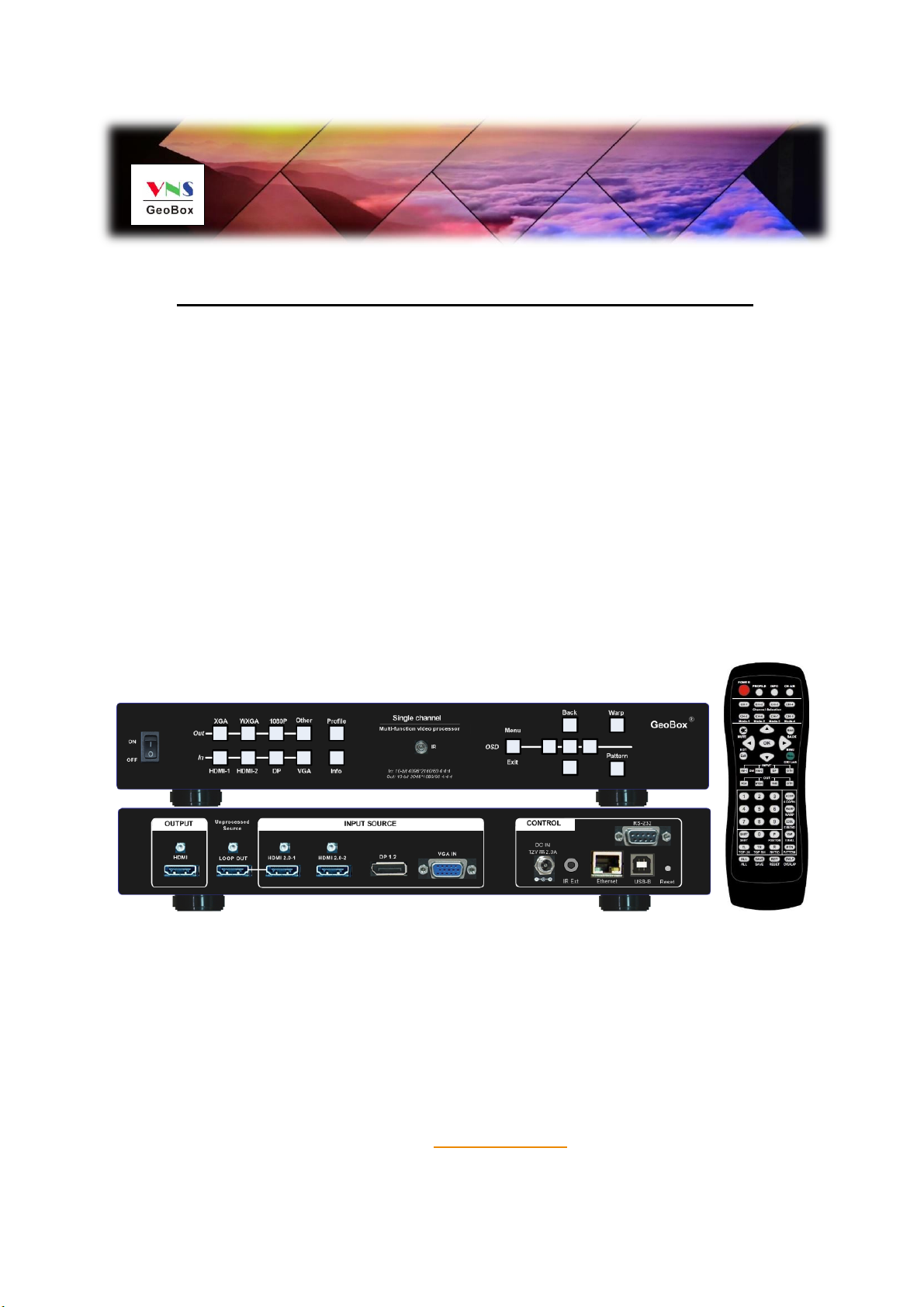
➢Each G116 has four input ports: 2x HDMI, 1x DP, 1x VGA. User can select input port from
remote controller or front panel keypad.
➢HDMI & DP input ports support up to 4096x2160 @60 Hz, 8k/1k @30 Hz.
➢G116 can support non-VESA standard input timing once signal source can provide, such as
4096x2160, 3200x2400…
➢Only HDMI-1 input signals can be looped out. Loop out signal is unprocessed source signal.
➢One HDMI output up to 2048*1080/60Hz. User can select output resolution front remote
controller or front panel keypads. Output resolution list: 720x480, XGA, WXGA, 1280x1024,
1366x768 ,1400x1050, 1600x1200, 1920x1080 (24/30/50/60Hz), 2048x1080/60 &
1920*1200/60。All output default resolution is 60Hz, RGB 4:4:4 and progressive.
➢[OTH] key in remote controller will show other output timings on the screen except XGA,
WXGA, 1080P. User can select desired timing from OSD.
Input connectors
Output connector
Loop Out

G116 User Guide Document: G116-1
--------------------------------------------------------------------------------------------------------------------------------------------
7
➢PIP/POP is integrated in each processing channel. However, only one HDMI input signal can
be selected in PIP/POP application. Please see more details in PIP/POP section.
➢If the output refresh rate is not the same as input refresh rate. The frame lock function will be
disabled and it may cause not synchronization issue among output channels. If the input is
4k/30 with FHD/60 output, it will have no synchronization problem. If the input is 50Hz, please
select 1080p 50 Hz output to avoid frame repeat issue.
➢User can click [Info] key to get system information and input / output signal resolution.
2.2. LED indicators
➢LED indicators will show the input/output signal status.
Select input port and output
resolution.
Select output resolution
Select input port
LED indicator for input
port
LED indicator for output
port
G116 User Guide Document: G116-1
--------------------------------------------------------------------------------------------------------------------------------------------
8
➢If user presses Menu key for 5 seconds on the remote controller, GeoBox OSD menu will be
locked and the Power LED will be flashing. To press another 5 seconds, it will unlock OSD
menu.
➢If multiple units are used in the system, user can set different ID and use remote controller [85x]
key to execute independent control. Press [851] following other OSD keys, the remote
controller can only show Box ID #1 OSD and Power LED on front panel in other units will be
flashing. User can disable OSD LOCK with [850] command via IR controller.
2.3. System connection and Power On
➢Poor quality HDMI cable and signal source will affect the connection distance and may cause
signal noise or show intermittent image.
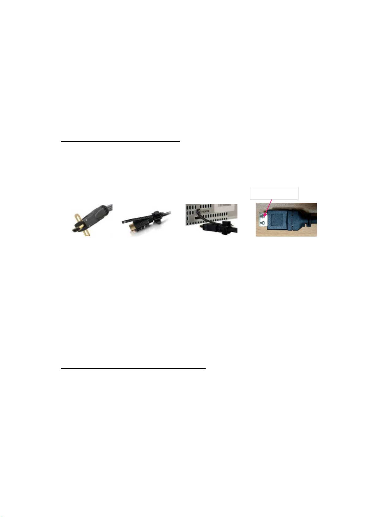
➢To ensure all cables are connected correctly, it is recommended to use locking cables. We can
provide T-Lock cable with certified quality.
➢Complete system should be connected to one power Distribution Box with proper grounding.
Power on the system after finishing all connections to avoid system damage by floating voltage
among devices.
➢When power is switched on, the booting time is about 19 seconds and the Input & Output LEDs
on front panel will stay “Lighted”all the time for the channel with correct input source and output
device connections.
➢If continuous flashing in power LED, it means the OSD function has been Locked. Please press
[Menu] key for 5 seconds to disable [OSD Locked] function. If system lock is done by remote
controller through [85x] operation, please press [850] to unlock system control.
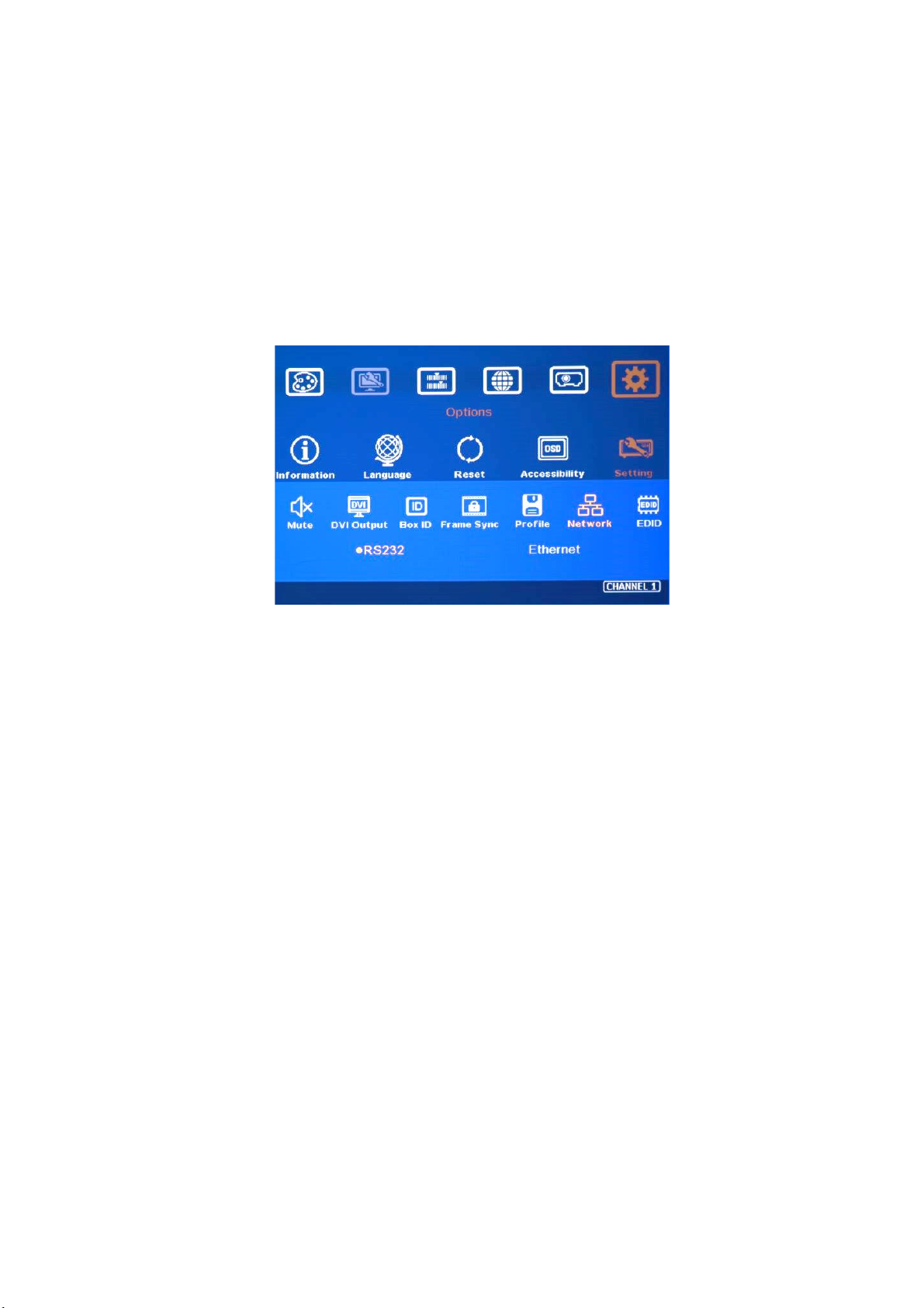
2.4. System settings: Box ID, RS232, Ethernet
➢Box ID, RS232 and Ethernet settings can be executed through OSD menu, WebGui or Gwarp3
PC Tool.
➢User can control or operate G116 settings through Ethernet. Default IP address is
192.168.0.100.
➢When multiple units are used at the same time, user can set different IP address in each G116
so that each G116 can be controlled independently.
2.4.1. Box ID
➢The range of Box ID is 0 ~ 99 for RS232 command.
T-Lock cable
G116 User Guide Document: G116-1
--------------------------------------------------------------------------------------------------------------------------------------------
9
➢If user uses remote controller to execute system operation, the Box ID range is 0 ~ 9.
2.4.2. RS232 settings
➢RS232 is designed with DB-9 connector. User can select baud rate between 11520 and
9600.
➢We can provide UART protocol for the control from RS-232 or Ethernet.
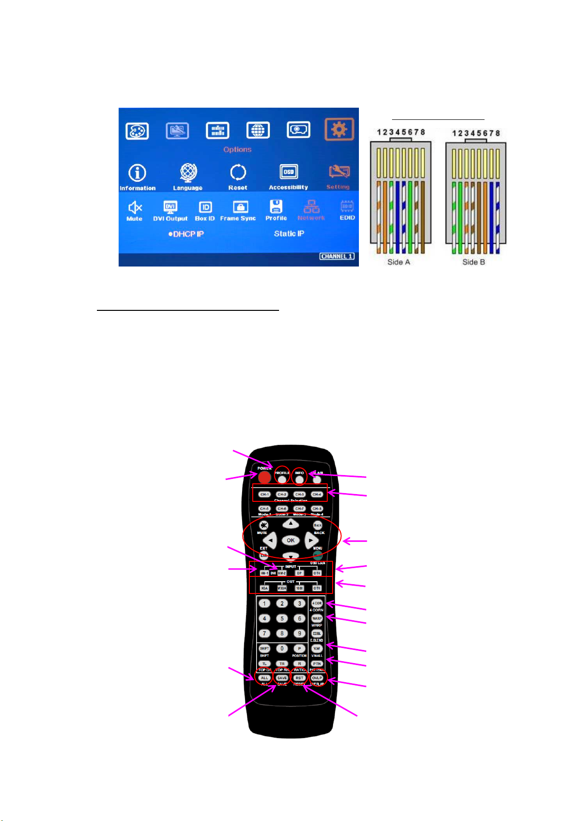
2.4.3. Ethernet
➢User needs to connect G116 to WiFi Router or switch/hub through RJ45 to LAN port. Then
user can control the system through Ethernet.
➢Crossover UTP cable can be used for direct connection between PC and GeoBox. User
needs to set PC TCP/IPv4 with the same domain segment as GeoBox (for instance, to set
IP address at 192.168.0.105) and subnet mask at 255.255.255.0).
➢Open web browser (Google Chrome or Internet Explorer) and input G116 IP address
(default is 192.168.0.100), user can see GeoBox WebGui and menu with virtual keys
similar to OSD for further system operation. There is no additional software is required.
➢If user can’t connect the network, please power off/on G116 again to let PC detect G116
network system.
➢User can set DHCP for the connection. If necessary, please [Renew] DHCP to get IP
address before network connection.
➢Gwarp3 PC Tool is another web tool that has full function for system setting and operation.
It can also update Firmware or MCU code. Gwarp3 can be downloaded from VNS website.
➢Each G116 can set different IP address for independent operation and control.
➢Please use < > OSD keys to select OSD menu items and use ˄˅OSD keys to change IP
address.
➢If G116 is connected with WiFi Router (through LAN port), user can control G116 through
WiFi via PC, iPad or mobile phone.
G116 User Guide Document: G116-1
--------------------------------------------------------------------------------------------------------------------------------------------
10
➢Default TCP server port is 1266.
2.5. How to use IR Remote Controller
➢IR remote controller has full functions for the operation of G116.
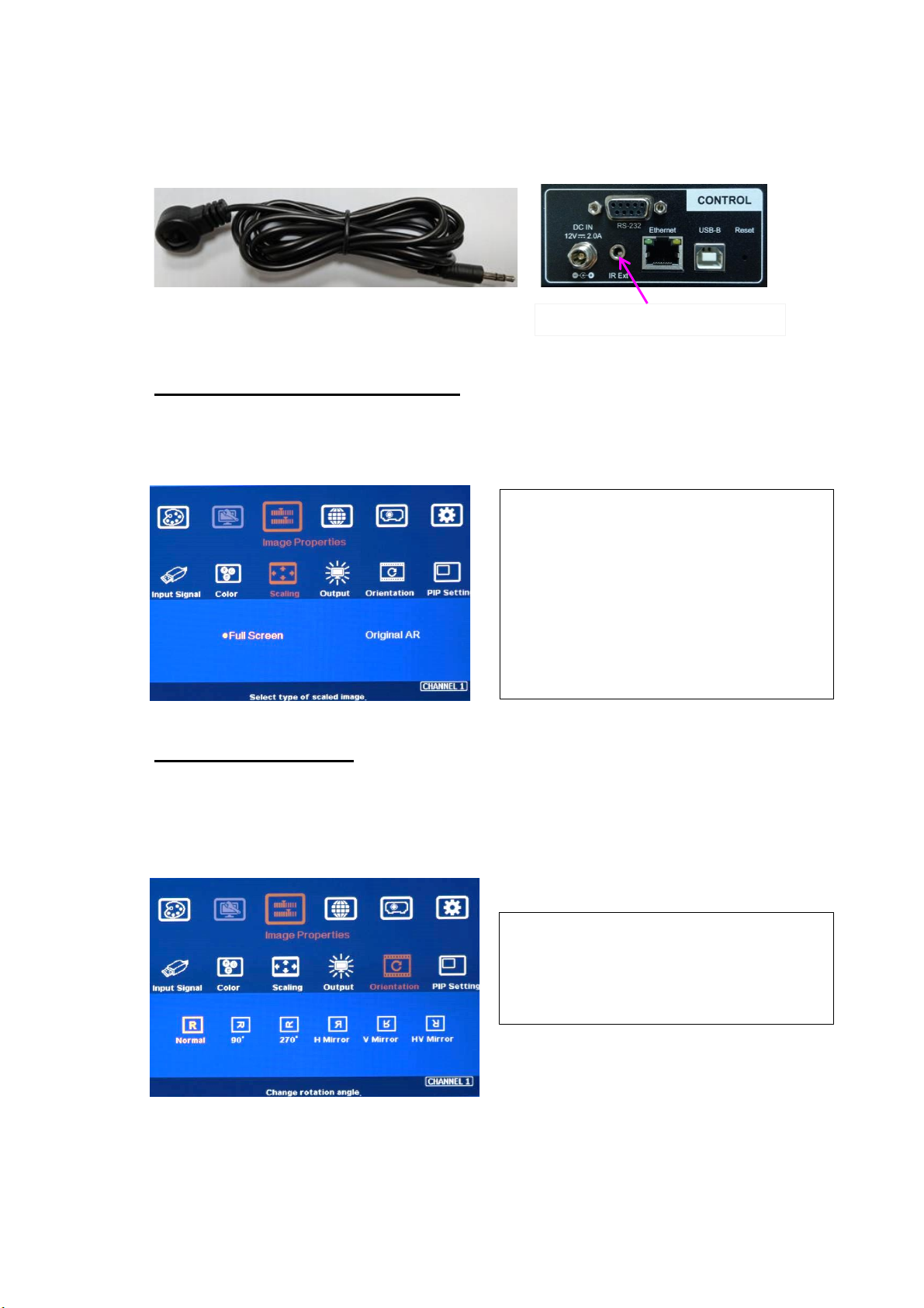
➢IR receiver is on Front Panel. One 3.5ø mm audio connector for IR extender is located at Back
Panel of G116. 1.8m IR extension cable is equipped in the packing. User can add audio cable
to extend the distance up to more than 20 meters.
➢IR remote control system is possible to be interfered and cause abnormal or discontinuous
operation. Under this condition, Ethernet operation may be the best choice.
System Information
Channel selection
OSD Menu operation keypads
Input source selection
Output resolution selection
Power on/off. If power
off by remote controller,
please power on by
remote controller
Profile [Load] shortcut key
[Video Wall] Menu
HDMI-2 input port
HDMI-1 input port
RC-400
System reset menu
Profile [Save] menu
Video Wall [Overlap]
Work with other function keys to
execute function to all channels
at the same time. Only some
functions are available.
[4 Corner] geometry alignment
[Warp] curve geometry alignment
Crossover UTP cable
Grid pattern
Crossover UTP cable
G116 User Guide Document: G116-1
--------------------------------------------------------------------------------------------------------------------------------------------
11
2.6. Full screen and native aspect ratio
➢[Scaling] under [Image Properties] menu is to select the display mode either following signal
source original aspect ratio or full screen display
2.7. Image rotation and flip
Image 90/270 degrees rotation can support up to 4k/60Hz input signal. When the image is rotated or
flipped, the OSD will still keep at original direction without change. The direction for [Video Wall]
settings still follow the image direction after rotated or flipped.
- [Full Screen]: to display full screen image
no matter the input source is in what kind
of aspect ratio.
- [Original AR]: the output display will keep
the same display aspect ratio as signal
source original aspect ratio. If the input is
4:3, then the output display will keep the
same 4:3 aspect ratio.
- Image flip is for projector to project image
from rear or top position.
- After image rotation or flip, the OSD will
still keep at the original direction.
Audio connector for IR extender

G116 User Guide Document: G116-1
--------------------------------------------------------------------------------------------------------------------------------------------
12
2.8. Color adjustment
2.8.1. Global color adjustment: [Picture]
2.8.2. Preset Color Temperature and independent RGB color adjustment
2.9. OSD Lock and unlock
➢If multiple units of GeoBox is installed together or the IR receiver is put together, in order to
avoid interference among multiple GeoBox during the installation, user can set different ID
number for each GeoBox through [Options] Menu. Press number keys in Remote Controller to
determine which GeoBox will be controlled.
- 851: control GeoBox ID No. 1
- 853: control GeoBox ID No. 3
- 850: to unlock all units and user can control all GeoBox.
- User will see flashing LED on front panel after press 85x number keys. It means the OSD
menu in GeoBox with flash LED is locked and will not be controlled by remote controller.
➢OSD Lock / Unlock: When continuously press [Menu] key in IR Remote Control for 5 seconds,
the OSD function will be locked to prevent from setting change by negligence. To press [MENU]
key for 5 seconds again, it will unlock OSD and user can manipulate the OSD again.
- [Picture] can execute below color
adjustment for each processing channel.
- When input is 4:2:2 video:
[Brightness], [Contrast], [Hue],
[Saturation] & [Sharpness]
- When input is RGB 4:4:4:
[Brightness], [Contrast] & [Sharpness]
- [Color] under [Image Properties] menu
can change preset color temperature and
discrete [RGB] color in each channel.
- [Preset Mode]: [Neutral], [Reddish],
[Bluish]
- [Custom]: discrete RGB color adjustment

G116 User Guide Document: G116-1
--------------------------------------------------------------------------------------------------------------------------------------------
13
2.10. System synchronization
When the system uses multiple G116, the image should be synchronized together. GeoBox uses
[Frame Sync] to synchronize all outputs based on the input signal vertical sync. When [Frame Sync]
is applied, it is possible to lose sync during system setup and cause the projector to re-search the
signal source. In order to provide smoother setup, GeoBox provides OSD for user to select different
synchronization methods for easy setup.
➢[Normal] (Frame Locked): We propose to set at [Normal] in most of the applications. When user
reset system or adjust video wall settings, user will see projector re-searching the input source.
➢[Fast]: time to sync the input source will be fast than [Normal]. During video wall settings,
projector will reduce re-search behavior and will have smoother setup process.
➢[Disable] (Free-Run mode): when GeoBox changes input source or timing, the output will still
send out continuous output signal. The projector has lowest chance to re-search the input
signal while system setup.
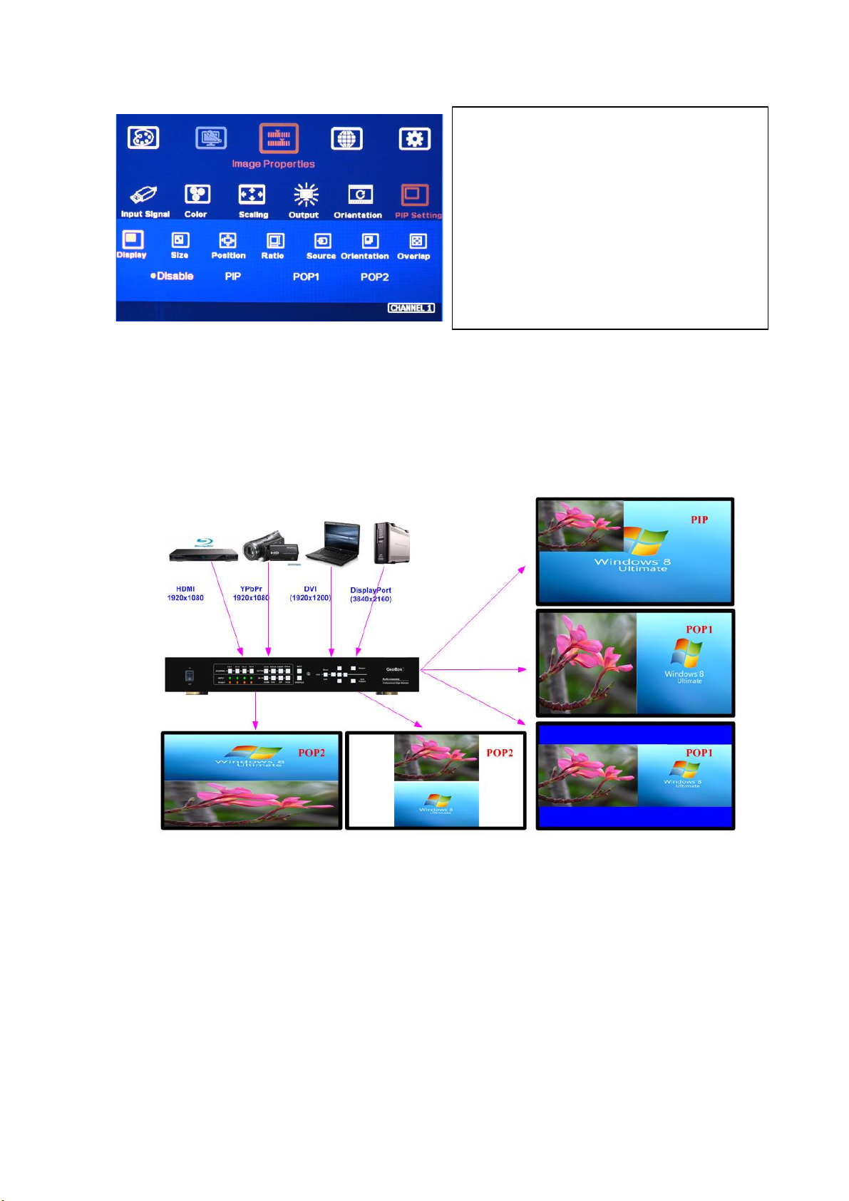
2.11. PIP/POP -- Dual window display
➢Picture in Picture (PIP) function is to display up two images from one processing channel. The
minimum size of sub-image is 320*180 Pixels and maximum size is 1920*1200 pixels.
➢The location of the PIP image can be controlled by OSD menu at any location inside main image.
➢The size of the PIP image is also flexible and can be controlled by OSD menu.
✓PIP: Picture in Picture
✓POP: Picture Outside Picture
✓PIP sub-image maximum size: 1920*1200
✓90/270 image rotation is not available under
PIP/POP function.
✓Both main and sub-image will go through
high end video with best video quality.
G116 User Guide Document: G116-1
--------------------------------------------------------------------------------------------------------------------------------------------
14
➢Display: Under Display menu, there are four items:
⬧Disable: disable PIP or POP function
⬧PIP: select PIP (picture in picture) display function
⬧POP1: POP mode at side by side display mode.
⬧POP2: POP mode at top/bottom display mode.
➢Size: (Only apply to PIP function)
⬧The size of the PIP image can be adjusted though [Size] OSD menu.
⬧The minimum PIP size is 320*180 and maximum size of PIP image is 1920*1080 pixels.
⬧PIP image can be displayed with full screen in the output. Further aspect ratio, image size or
cropping area can be implement through [Overlap] function under [PIP Settings] menu.
➢Position: (only apply to PIP function)
⬧The position of PIP image can be adjusted in H&V directions through Position OSD menu.
⬧The PIP image will be maintained inside one projector and can’t be outside main image.
⬧Pixel by Pixel PIP image position adjustment.
Menus under [PIP setting]:
--Display: enable PIP or POP
--Size: set PIP size
--Position: set PIP position
--Ratio: set PIP/POP display aspect ratio
--Source: select input source for PIP/POP
--Orientation: rotate sub-image direction
--Overlap: adjust PIP image cropping area,
position and aspect ratio.
G116 User Guide Document: G116-1
--------------------------------------------------------------------------------------------------------------------------------------------
15
⬧Further position fine-tune can be executed from [Overlap] menu.
➢Source:
⬧The input source for PIP/POP is selectable. Main image can be selected from [Input Signal]
under [Image Properties] menu or remote controller hot key. Sub-image shall be selected from
[Source] under [PIP Setting] menu.
⬧Only HDMI + DP, DP+VGA or HDMI+VGA can be selected as PIP/POP sources.
⬧No two HDMI input sources can be as main and sub-image sources at the same time unless
user adds one HDMI to DP adapter to connect HDMI source from DP port.
➢Ratio: Set Aspect Ratio of sub-image in PIP/POP.
⬧Full Screen: same aspect ratio as main image in PIP mode or full screen display in POP mode.
⬧Original AR: the same aspect ratio as sub-image input source.
⬧POP main image aspect ratio can be adjusted through [Scaling] under [Image Properties] OSD
menu. Sub-image aspect ratio can be adjusted through [Ratio] menu under [PIP Setting] and
[Overlap] function under [PIP Settings] menu.
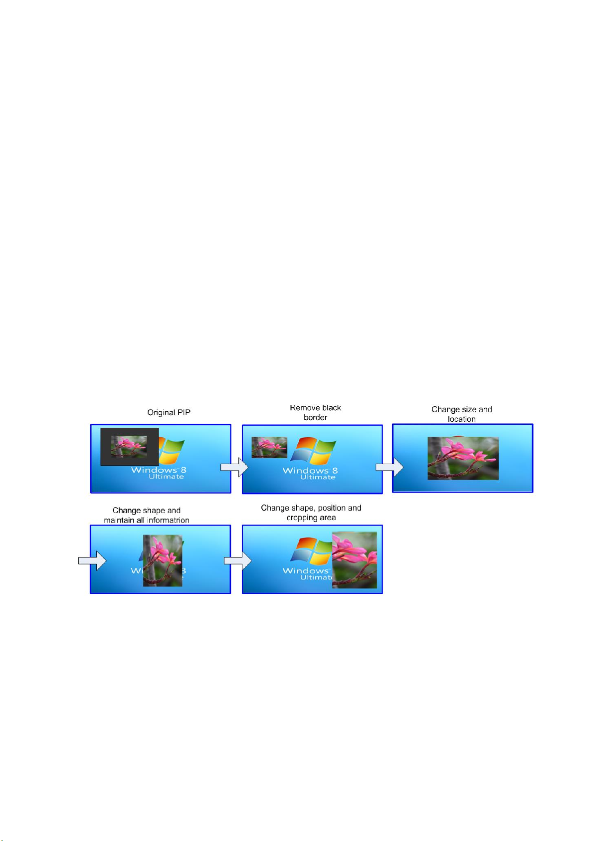
➢Overlap: adjust cropping area and aspect ratio of PIP image
⬧User can execute further image cropping and aspect ratio change in PIP/POP image.
⬧After further Overlap adjustment, user can further enlarge PIP image range from 180*90 pixels
up to WUXGA resolution. User can also adjust image size in POP mode.
➢[Orientation] for PIP/POP
⬧When PIP/POP is implemented, main image and sub-image can’t be rotated at 90/270
degrees. Only 180 degrees rotation or RH/LH image flip and UP/Down flip function can be
executed. Both main and PIP image will go through high end 3D motion de-interlacing.
⬧Main image rotation shall be executed from [Orientation] under [Image Properties] menu and
Sub-image rotation shall be executed from [Orientation] under [PIP setting] menu.
⬧Main and sub-image can be rotated at different directions.

G116 User Guide Document: G116-1
--------------------------------------------------------------------------------------------------------------------------------------------
16
⬧When main image is 90/270 degrees rotated and user executes PIP/POP function, main image
will be returned to normal display direction. Image 180 degrees rotation or flip can still be
executed without change.
3. Geometry alignment
3.1. Select appropriate Grid Pattern for geometry alignment
Grid pattern is required for geometry alignment. User can activate test pattern through [Pattern] hotkey
in remote controller or through WebGui and Gwarp3 PC tool.
➢The default grid size is 32*32 pixels. User can select different grid size from 8-120 pixels. Each
channel can be set separately.
➢The OSD show-up time can be determined by [Options]→[Accessibility]→[Menu Time Out]. If set
at “0”, the OSD will show up all the time unless input timing is changed or OSD [Exit].
➢If user executes Geometry alignment, the pattern will appear automatically after select the
adjusting point and press Enter.
➢There are 6 pattern styles for user to select. When user presses [Pattern] key, it will circulate from
[White]→[Red]→[Green]→[Yellow]→[Cyan]→[White grid + background]→[OSD menu +
Background]
➢If user wants to apply his own test pattern, please select the last transparent pattern mode to show
up background user pattern.
➢User can select different pattern color for each projector while doing image stacking setup.
➢User can see geometry adjusting value when select [Background + OSD] display style.

G116 User Guide Document: G116-1
--------------------------------------------------------------------------------------------------------------------------------------------
17
3.2. Grid pattern pixel size selection
➢The grid size in both horizontal and vertical directions is from 8 to 120 pixels with 1-pixel
increasement. H&V grid size will be the same.
➢Default grid size for both H&V directions are 32x32.
➢If 120 pixels grid size is selected, the grid pattern will be at the same position as 17x17
geometry adjustment control points.
3.3. Geometry alignment
[2x2] 4 Corner alignment hotkey
[3x3], [5x3], [9x5] Warp hotkey

G116 User Guide Document: G116-1
--------------------------------------------------------------------------------------------------------------------------------------------
18
3.3.1. Geometry alignment through remote controller
➢[OSD Time Out] is default to ”0”. It will ensure the grid pattern will not be turned off
automatically. Input mode change will disable OSD and grid pattern.
➢User can install IR extender receiver near screen for easy GeoBox operation (if necessary,
please add audio extending cable to extend the distance up to 20 meters). If multiple units
of GeoBox are used and IR receivers are put together, please set [Box ID] for each G116
so that user can control each G116 separately through [85x] command. Press number
keys in Remote Controller following OSD menu for the control of multiple GeoBox:
- 850: will activate all GeoBox. User can execute simultaneous control for all GeoBox
- 851: activate only ID #1 GeoBox for further control.
- 852: activate only ID#2 GeoBox for further control.
3.3.2. [2x2] 4 corner geometry alignment
[2x2] alignment will adjust whole image with the same scaling factor. [Warp] alignment will
adjust only some portions of the image.
3.3.3. [3x3], [5x3], [9x5] Warp alignment
➢After finish [2x2] corner alignment, apply [3x3], [5x3], [9x5] geometry alignment.
➢Please follow the sequence [2x2]→[3x3]→[5x3]→[9x5] to do geometry alignment to
ensure entire image will have uniform scaling factor.
[2x2] 4 Corner alignment hotkey

G116 User Guide Document: G116-1
--------------------------------------------------------------------------------------------------------------------------------------------
19
➢After finish Warp alignment, user can use [2x2] for complete image position fine tune
without changing the Warp result. If user executes [3x3] alignment again after [9x5]
alignment, [9x5] grid position will be reset and only keep [3x3] grid point information.
➢Geometry alignment range from remote controller can be up to 600 pixels in [2x2] + 600
pixels more in [3x3] for one corner/edge.
3.3.4. Linearity grid line adjustment
The control point can shift the lines in both horizontal and vertical directions.
➢Linearity grid line adjustment is under [3x3], [5x3] & [9x5] warp alignment menu. User can
select the control point, then press ENTER to do grid line adjustment. Each control point
can shift the image in both horizontal and vertical directions.
➢When user projects the image to curved screen, the image grid size will continuously
change—the grid size at the center will be bigger than both sides. Ultra-short throw
projector will be more serious. Linearity grid line adjustment is designed to correct this kind
of grid line gap difference.
➢Linearity Grid Line adjustment can shift both horizontal and vertical grid lines. The
maximum adjusting points in OSD menu is H=9, V=5. For [3x3], the adjusting range is
+_600 pixels in each direction. This function is not available in Gwarp3 PC tool.
[3x3] warp hotkey
Table of contents
Other VNS Media Converter manuals


