© modernpack
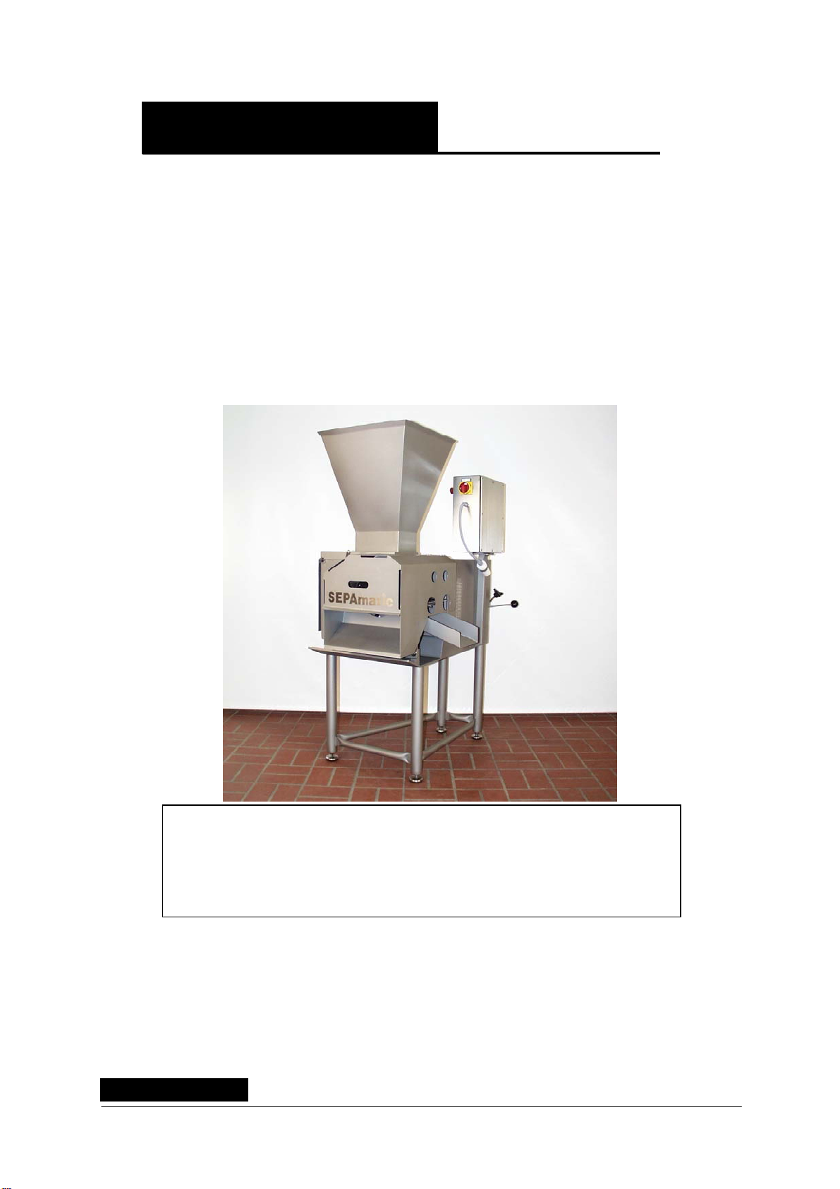
ENJJJF SEPAmatic 410 T
- 6 -
2. Principle of separator operation
The apparatus is a continuous raw material processing machine. Using a standard trolley and
a lifting/tilting device, the feed material is placed in the metering machine delivery hopper,
from where it enters the feed zone of the actual separating machine in measured quantities.
Upstream machines such as mixers, mincers or strip cutters can also be used to convey
material into the square hopper (P300), directly by means of inclined or screw conveyors.
A highly flexible squeezing belt (P30) carries the raw material up to the revolving perforated
drum (P20).
Owing to the space reduction and increasing pressure, the softer components of the raw
material are pressed through the holes into the perforated drum (P20), while the solid parts
remain on the outer drum casing, from where they are removed by a knife.
The product obtained is removed from the perforated drum (P20) by the ejector (P240) for
further processing. Operating the separator machine without raw material – referred to as a
dry run – wears down the squeezing belt (P30) unusually quickly. For this reason the machine
should be switched off even for the shortest interruptions in work, as when carrying off or
fetching new product.
Of great assistance in avoiding "dry runs" such as these is the automatic safety device
installed as standard known as FACONOP, which switches the machine on or off according
to whether raw material is present or not.
Even an irregular product feed from the store tank, which had previously led to blockages on
a regular basis, can be regulated by controlling the metering screw. This monitoring function
can be suppressed, if necessary, by deactivating the automatic switch (E60). The glass
surfaces of the associated sensors should be kept scrupulously clean.
The squeezing belt (P30) is pressed against the perforated drum (P20) by means of the
combined press and drive roller (P100), which permits precise and reproducible settings via
Press lever (P110) according to the product being processed.