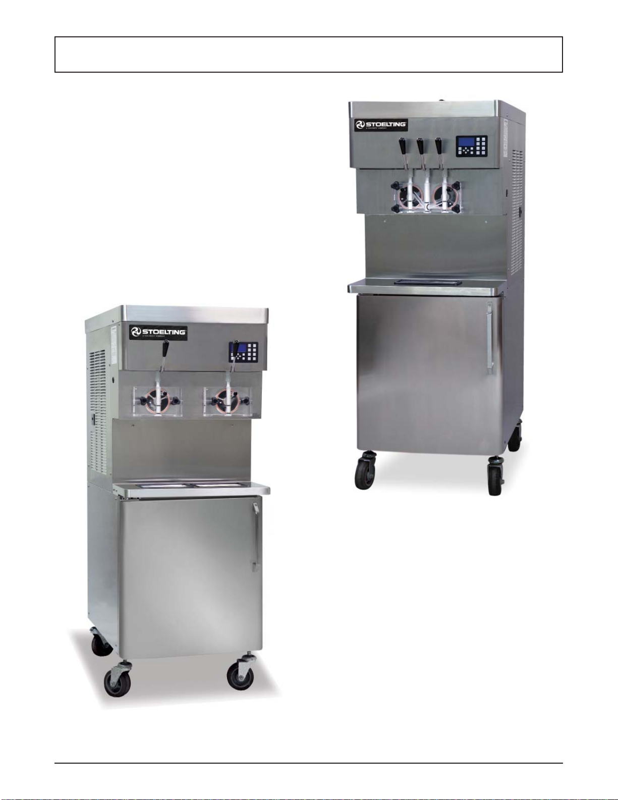
Service Manual #513721 11 U421-I2A & U431-I2A Model Machines
WATER VALVE ADJUSTMENT
A. Remove the lower front panel and side panel.
B. Connect a gauge to the compressor discharge
Schrader valve.
C. Connect the machine to the electrical supply, start
the refrigeration cycle, and read the pressure.
D. The proper gauge reading should be 225-235 psig.
The exit water temperature should be 95-107°F.
E. If the water temperature and high side pressure
are too low, the opening point pressure should
be increased to slow the water flow. Turn the
adjustment screw counterclockwise.
F. If the water temperature and high side pressure
are too high, the opening point pressure should
be decreased to increase the flow of water. Turn
the adjustment screw clockwise.
WATER VALVE REMOVAL
The water valve is connected to the refrigeration system
by capillary tube brazed to the discharge line.
A. Turn off and disconnect the water supply. Blow
out the water lines with compressed air or CO2.
B. Recover refrigerant charge per instructions in
Section 2.2.
C. Leave the suction and discharge ports open
to prevent pressure buildup during water valve
removal.
D. Unsweat the capillary tube from the discharge
line.
E. Cap or plug the refrigeration system if the water
valve will not be replaced immediately (within 10
minutes) to prevent contamination.
F. Remove the clamps from the water lines at the
valve.
G. Remove the two screws holding the water valve
to the frame and remove the valve.
WATER VALVE REPLACEMENT
To replace the water valve, perform the following proce-
dures:
A. Position the water valve and attach to the frame
using the two screws.
B. Install the water lines onto the valve with hose
clamps.
C. Leave the suction and discharge ports open
to prevent pressure buildup during water valve
installation.
D. Braze the capillary tube into the system.
E. Connect the water supply line and turn on the
water supply.
F. Check for leaks in the water lines. If there are no
leaks, turn off the water supply.
G. Replace the filter drier. Refer to Section 2.8 for
details.
H. Evacuate and recharge system per instructions
in Section 2.2.
I. Turn on the water and check for leaks in the water
lines with the refrigeration system running.
J. Adjust the valve as necessary.
2.7 SOLENOID (AIR COOLED REMOTE ONLY)
Solenoid valves are installed on the freezing cylinder liquid
lines in air cooled remote machines. A solenoid valve has
a magnetic coil that, when energized, lifts a plunger and
allows refrigerant to flow. The solenoids are activated by
the IntelliTec2 control and determine which evaporator
receives refrigeration.
ACTIVATING A SOLENOID
To activate a solenoid, follow these steps:
A. From the Current Status screen, press the right
arrow, SET, then the SEL button to access the
technician level on the control.
B. Navigate to the Left Output Control or Right Output
Control menu which is located under Utilities in
the Testing and Manual Operation screen. Refer
to Section 4 for details.
C. Activate the solenoid by moving the cursor to
the Liquid Solenoid option and pressing the SET
button.
NOTE
Any energized component will deenergize after
leaving the Testing and Manual Operations menu.
SOLENOID TESTING
The following test will check if a liquid line solenoid has
a leaking valve seat. The power to the solenoid is dis-
connected and refrigerant flow is monitored through the
system. If the valve seat does not leak, the suction pres-
sure during the test will be low.
A. Attach a gauge to the Schrader valve on the
suction line.
B. From the Current Status screen, press the right
arrow, SET, then the SEL button to access the
technician level on the control.
Figure 2-11 Solenoid Valve