4 LINEAR ACTUATOR INSTALLATION
Cable Tray Power Bar will need to be plugged in a power source to complete actuator
installation.
4.1 ATTACH LINEAR ACTUATOR TO BRACKETS
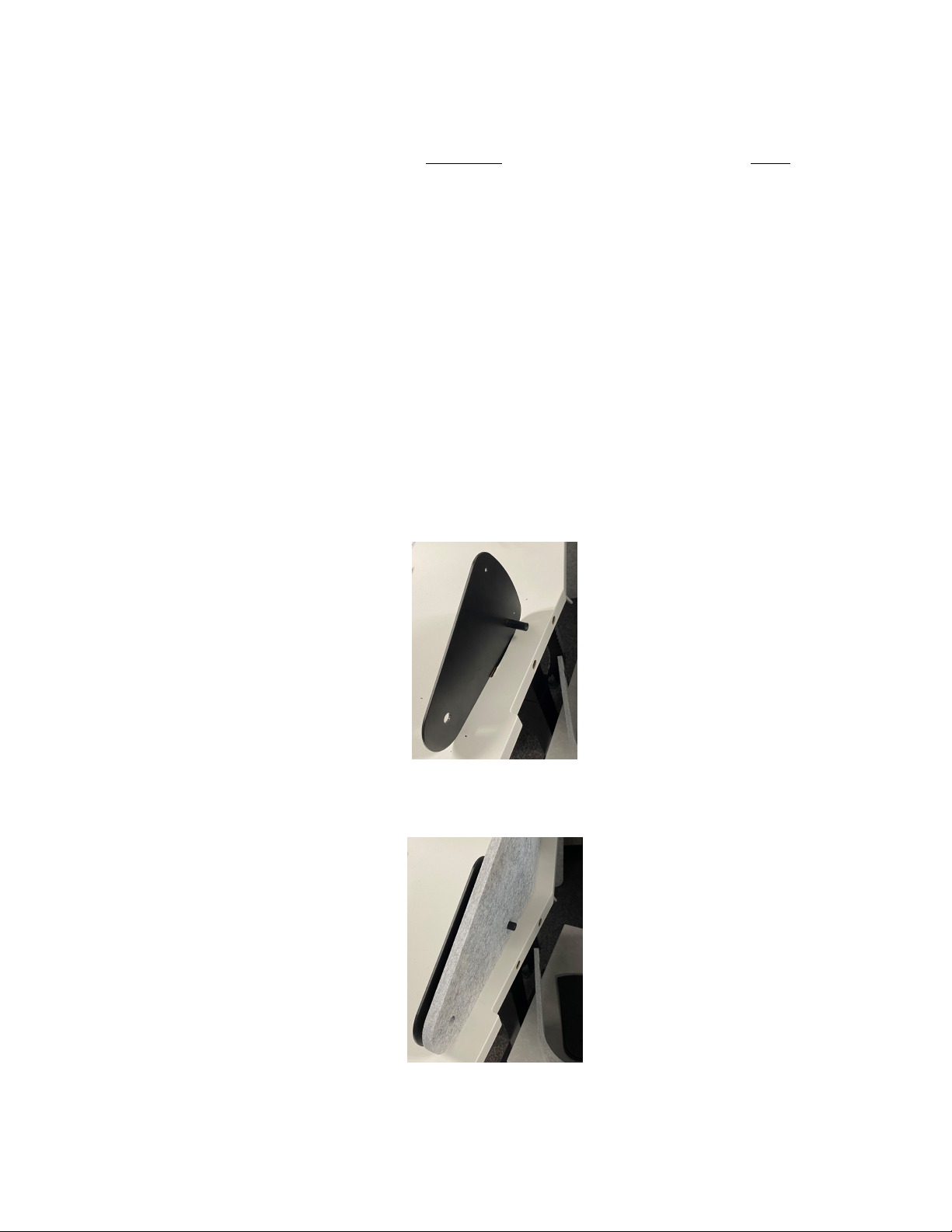
1. Place back of ACTUATOR(H) into ACTUATOR BRACKET(G) and remove cotter pin from PIN(C)
and insert PIN(C) through ACTUATOR BRACKET(G) and hole in ACTUATOR(H). Reinsert cotter
pin into PIN(C) on the other side of ACTUATOR BRACKET(G).
2. Plug both ACTUATORS(H) into ACTUATOR CONTROL BOX(I), then place face plate removed in
STEP 1.4 back onto the ACTUATOR CONTROL BOX(I).
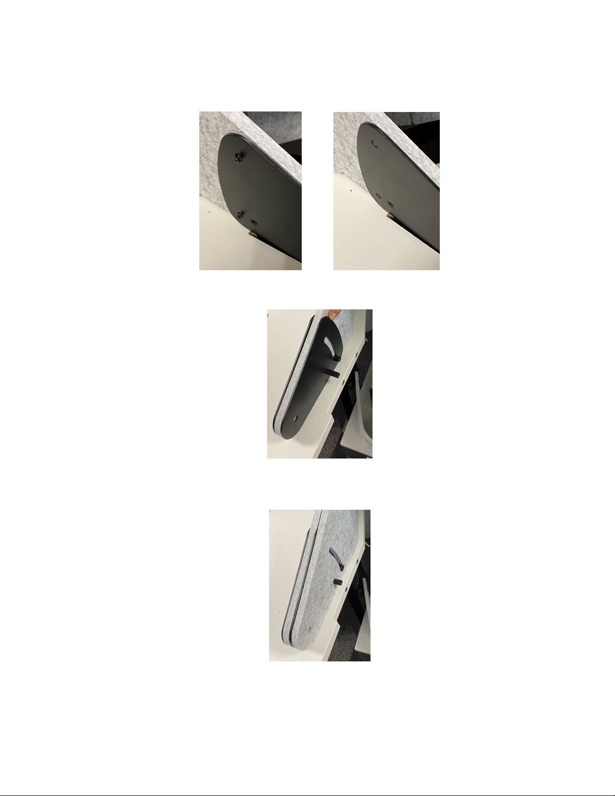
3. Using down button on DOME HAND CONTROL(J), position other end of ACTUATOR(H) such that
the hole on J BRACKETS(ALEFT) & (BRIGHT) are lined up with hole on ACTUATOR(H).
4. Place SPACER(E) between ACTUATOR(H) and J BRACKETS(ALEFT) & (BRIGHT). Insert PIN(C)
through bracket, SPACER(E), and actuator. Secure PIN(C) with cotter pin on other end.
4.2 INSTALL ACTUATOR SHROUDS
1. Take the PANEL(A) and align holes in the shroud with those on the side of the worksurface. Using
7 BOLT(A) secure PANEL(A) to worksurface. Install 2 additional BOLT(A) through front of panels
into brackets.
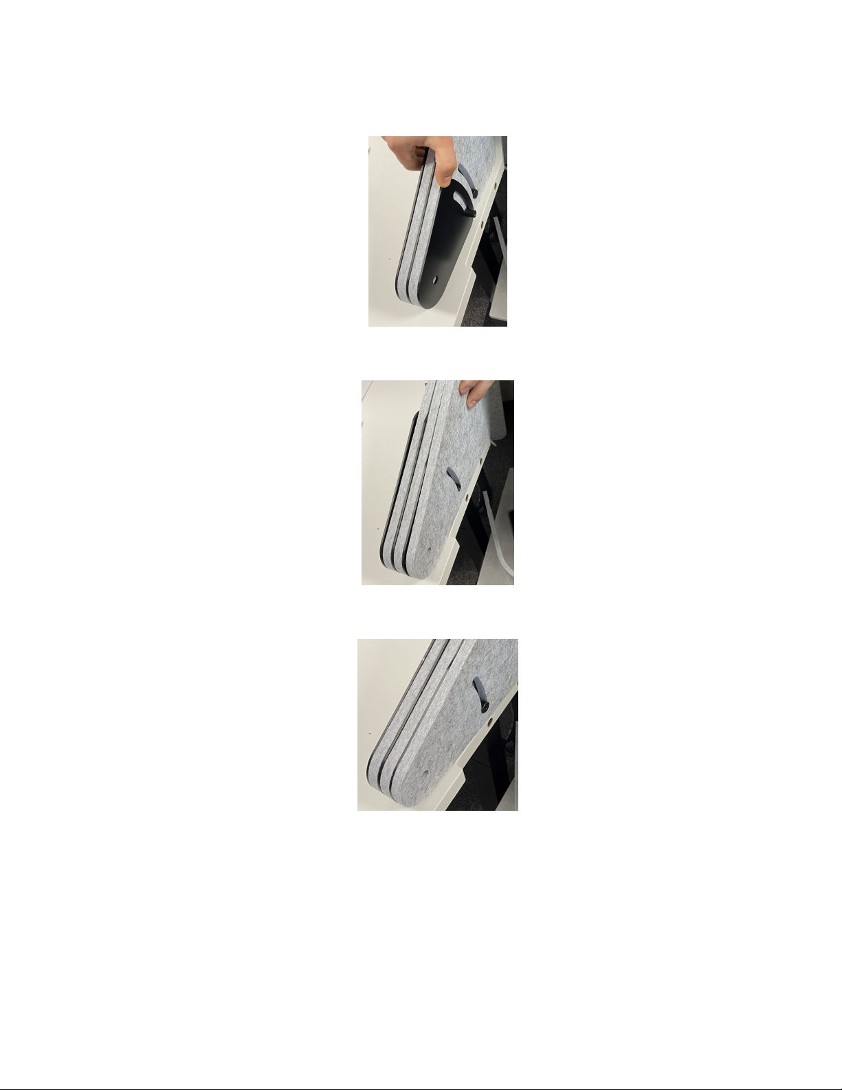
2. SHROUDS(ALEFT) & (BRIGHT) are not symmetric and will need to be placed with the beveled edge
facing the worksurface.
3. Line SHROUD(ALEFT) on the outside of the worksurface and attach with BOLT(A). Repeat this step
on other side of worksurface with SHROUD(BRIGHT).
4. Extend SHROUD(ALEFT) straight out and insert MAGNET(F) into the hole at end of the piece from
the worksurface side (inside).
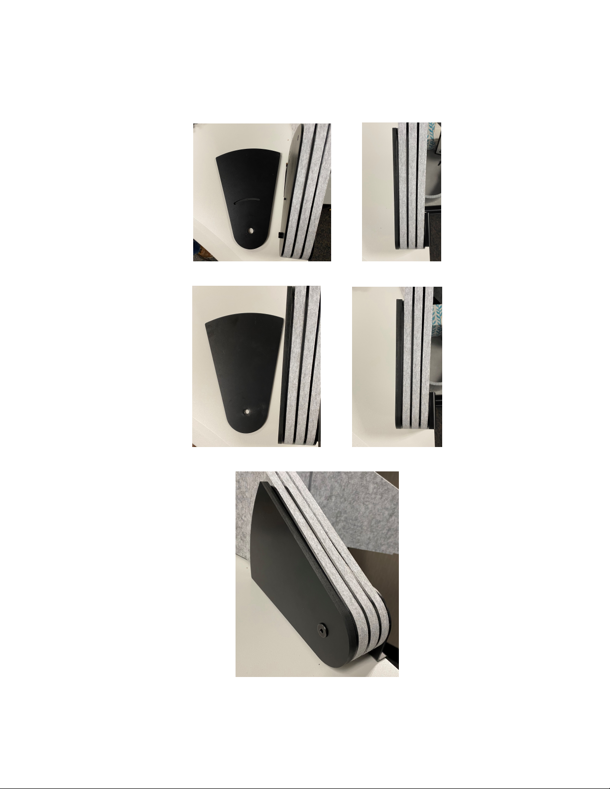
5. Wrap SHROUD(ALEFT) around the J BRACKET end of ACTUATOR(H) and attach to table base.
IT IS IMPORTANT TO ATTACH THE ACOUSTIC PIECE TO OUTSIDE OF THE
TABLE BASE NEAREST THE ACTUATOR.
7