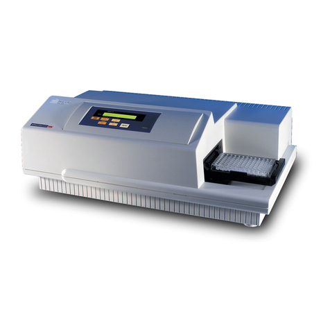
Molecular Devices SPECTRAmax 340PC User manual

SPECTRAmax
®
340PC
Microplate Spectrophotometer
Operator’s Manual
Molecular Devices Corporation
1311 Orleans Drive
Sunnyvale, California 94089
Part # 0112-0049
Rev. A

ii SPECTRAmax 340PC Microplate Spectrophotometer Operator’s Manual
Molecular Devices Corporation
SPECTRAmax
®
340PC Operator’s Manual
Copyright
Copyright 1998, Molecular Devices Corporation. All rights reserved. No part of this publication may
be reproduced, transmitted, transcribed, stored in a retrieval system, or translated into any language
or computer language, in any form or by any means, electronic, mechanical, magnetic, optical, chem-
ical, manual, or otherwise, without the prior written permission of Molecular Devices Corporation,
1311 Orleans Drive, Sunnyvale, California, 94089, United States of America.
Patents
The SPECTRAmax 340PC and methods are protected by the following patents:
U.S. Patents
4,968,148
and
5,112,134
;
Canadian Patent
1,305,334
.
Other U.S. and International patents pending.
Trademarks
Automix and PathCheck are trademarks and SPECTRAmax and SOFTmax are registered trademarks
of Molecular Devices Corporation.
Apple and Macintosh are registered trademarks of Apple Computer, Incorporated.
All other company and product names are trademarks or registered trademarks of their respective
owners.
Disclaimer
Molecular Devices Corporation reserves the right to change its products and services at any time to
incorporate technological developments. This manual is subject to change without notice.
Although this manual has been prepared with every precaution to ensure accuracy, Molecular Devices
Corporation assumes no liability for any errors or omissions, nor for any damages resulting from the
application or use of this information.
Molecular Devices Corporation Instrument Warranty
Molecular Devices Corporation warrants this product against defects in material or workmanship as
follows:
1) All parts of the SPECTRAmax 340PC Microplate Spectrophotometer are warranted for a period of
one (1) year from the original date of delivery.
1) All labor charges to repair the product for a period of one (1) year from the original date of delivery
will be paid by Molecular Devices Corporation.
1) This warranty covers the SPECTRAmax 340PC instrument only, and does not extend to any com-
puter, printer, software, reagents, or disposables used with the instrument.

SPECTRAmax 340PC Microplate Spectrophotometer Operator’s Manual iii
Labor and Parts
To obtain warranty service during the applicable warranty period, you must take the product or deliver
the product properly packaged in the original shipping materials and carton to an authorized Molecular
Devices Corporation service facility. You must call or write to the nearest Molecular Devices Corpora-
tion service facility to schedule warranty service. You may call Molecular Devices Corporation at the
telephone number or address below to locate the nearest service facility. You must schedule warranty
service
prior
to bringing or shipping the product for servicing. At the time of requesting warranty ser-
vice, you must present proof of purchase documentation which includes the date of purchase and Mo-
lecular Devices Corporation must have the enclosed Warranty Registration form completed, signed
and returned by you within ten (10) working days of the date of delivery.
This warranty only covers defects arising under normal usage and does not cover malfunctions of fail-
ures resulting from misuse, abuse, neglect, alteration, modification, or repairs by other than an autho-
rized Molecular Devices Corporation service facility.
Repair or replacement as provided under this warranty is the exclusive remedy of the purchaser (the
“Buyer”).
Molecular Devices Corporation (the “Seller”) shall not be liable for any incidental or
consequential damages for breach of any express or implied warranty on this product, except
to the extent required by applicable law. The Seller specifically excludes all express and im-
plied warranties including without limitation any implied warranty that the products sold under
this agreement are merchantable or are fit for any particular purpose, except such warranties
expressly identified as warranties and set forth in the Seller’s current operating manual, cata-
log or written guarantee covering such product. The Seller also makes no warranty that the
products sold under this agreement are delivered free of the rightful claim of any third party by
way of patent infringement or the like.
If the Buyer furnishes specifications to the Seller, the Buyer
agrees to hold the Seller harmless against any claim which arises out of compliance with the specifi-
cations.
Any description of the products contained in this agreement is for the sole purpose of identifying them.
Any such description is not part of the basis of the bargain, and does not constitute a warranty that the
products shall conform to that description. Any sample or model used in connection with this agree-
ment is for illustrative purposes only, is not part of the basis of the bargain, and is not to be construed
as a warranty that the products will conform to the sample or model. No affirmation of fact or promise
made by the Seller, whether or not in this agreement, shall constitute a warranty that the products will
conform to the affirmation or the promise.
For the name of the nearest authorized Molecular Devices Corporation service facility please contact
Molecular Devices at one of the following telephone numbers:
(408) 747-1700
(800) 635-5577 (U.S. and California)

iv SPECTRAmax 340PC Microplate Spectrophotometer Operator’s Manual

SPECTRAmax 340PC Microplate Spectrophotometer Operator’s Manual v
Contents
Contents . . . . . . . . . . . . . . . . . . . . . . . . . . . . . . . . . . . . . . . . . . . . . . . . . . . v
Figures . . . . . . . . . . . . . . . . . . . . . . . . . . . . . . . . . . . . . . . . . . . . . . . . . . . . vii
Table . . . . . . . . . . . . . . . . . . . . . . . . . . . . . . . . . . . . . . . . . . . . . . . . . . . . . vii
Conventions Used in this Manual . . . . . . . . . . . . . . . . . . . . . . . . . . . . . . .viii
Glossary of Terms . . . . . . . . . . . . . . . . . . . . . . . . . . . . . . . . . . . . . . . . . . .viii
Chapter 1— Instrument Description . . . . . . . . . . . . . . . . . . . . . . . . . . . . . . . . . . . . . . . . . 1-1
Introduction. . . . . . . . . . . . . . . . . . . . . . . . . . . . . . . . . . . . . . . . . . . . . . . 1-3
General Overview. . . . . . . . . . . . . . . . . . . . . . . . . . . . . . . . . . . . . 1-3
PathCheck™ Sensor . . . . . . . . . . . . . . . . . . . . . . . . . . . . . . . . . . 1-4
Component Description . . . . . . . . . . . . . . . . . . . . . . . . . . . . . . . . . . . . . 1-5
The Control Panel . . . . . . . . . . . . . . . . . . . . . . . . . . . . . . . . . . . . 1-5
LCD . . . . . . . . . . . . . . . . . . . . . . . . . . . . . . . . . . . . . . . . . . . . 1-6
Keys. . . . . . . . . . . . . . . . . . . . . . . . . . . . . . . . . . . . . . . . . . . . . 1-6
Status Indicators. . . . . . . . . . . . . . . . . . . . . . . . . . . . . . . . . . . . . . 1-8
The Microplate Drawer . . . . . . . . . . . . . . . . . . . . . . . . . . . . . . . . 1-9
Microplates . . . . . . . . . . . . . . . . . . . . . . . . . . . . . . . . . . . . . . . 1-9
Templates . . . . . . . . . . . . . . . . . . . . . . . . . . . . . . . . . . . . . . . . 1-9
The Back Panel . . . . . . . . . . . . . . . . . . . . . . . . . . . . . . . . . . . . . 1-10
Functional Description . . . . . . . . . . . . . . . . . . . . . . . . . . . . . . . . . . . . . 1-11
Instrument Settings . . . . . . . . . . . . . . . . . . . . . . . . . . . . . . . . . . 1-11
Saving a Protocol . . . . . . . . . . . . . . . . . . . . . . . . . . . . . . . . . . 1-11
Recalling a Saved Protocol . . . . . . . . . . . . . . . . . . . . . . . . . . . 1-11
Modes of Stand-Alone Operation. . . . . . . . . . . . . . . . . . . . . . . . 1-12
Endpoint . . . . . . . . . . . . . . . . . . . . . . . . . . . . . . . . . . . . . . . . 1-12
Kinetic. . . . . . . . . . . . . . . . . . . . . . . . . . . . . . . . . . . . . . . . . . 1-12
Blank Pattern. . . . . . . . . . . . . . . . . . . . . . . . . . . . . . . . . . . . . 1-13
Wavelength Selection. . . . . . . . . . . . . . . . . . . . . . . . . . . . . . . . . 1-14
Temperature Regulation . . . . . . . . . . . . . . . . . . . . . . . . . . . . . . 1-14
Automix. . . . . . . . . . . . . . . . . . . . . . . . . . . . . . . . . . . . . . . . . . . 1-15
Data Collection . . . . . . . . . . . . . . . . . . . . . . . . . . . . . . . . . . . . . 1-16
Printed Data Output . . . . . . . . . . . . . . . . . . . . . . . . . . . . . . . . . 1-16
Default Override Control . . . . . . . . . . . . . . . . . . . . . . . . . . . 1-16
Computer Control . . . . . . . . . . . . . . . . . . . . . . . . . . . . . . . . . . . 1-17
SOFTmax
®
PRO. . . . . . . . . . . . . . . . . . . . . . . . . . . . . . . . . . 1-17
Specifications . . . . . . . . . . . . . . . . . . . . . . . . . . . . . . . . . . . . . . . . . . . . . 1-19
Chapter 2—Installation. . . . . . . . . . . . . . . . . . . . . . . . . . . . . . . . . . . . . . . . . . . . . . . . . . . . 2-1
Installation Warnings. . . . . . . . . . . . . . . . . . . . . . . . . . . . . . . . . . . . . . . . 2-3
Installation Cautions . . . . . . . . . . . . . . . . . . . . . . . . . . . . . . . . . . . . . . . . 2-3
Unpacking . . . . . . . . . . . . . . . . . . . . . . . . . . . . . . . . . . . . . . . . . . . . . . . . 2-3
Setting Up for Stand-Alone Use. . . . . . . . . . . . . . . . . . . . . . . . . . . . . . . . 2-4
Setting Up for Computer Control . . . . . . . . . . . . . . . . . . . . . . . . . . . . . . 2-4
vi SPECTRAmax 340PC Microplate Spectrophotometer Operator’s Manual
Chapter 3—Stand-Alone Operation . . . . . . . . . . . . . . . . . . . . . . . . . . . . . . . . . . . . . . . . . . 3-1
Prepare for a Reading . . . . . . . . . . . . . . . . . . . . . . . . . . . . . . . . . . . . . . . . 3-3
Turn the Instrument and Printer On . . . . . . . . . . . . . . . . . . . . . . 3-3
Set the Temperature. . . . . . . . . . . . . . . . . . . . . . . . . . . . . . . . . . . 3-3
Choose a Read Mode . . . . . . . . . . . . . . . . . . . . . . . . . . . . . . . . . . 3-3
Using a Blank Pattern . . . . . . . . . . . . . . . . . . . . . . . . . . . . . . . 3-3
Endpoint Mode . . . . . . . . . . . . . . . . . . . . . . . . . . . . . . . . . . . . 3-4
Kinetic Mode. . . . . . . . . . . . . . . . . . . . . . . . . . . . . . . . . . . . . . 3-5
Select the Wavelength(s) . . . . . . . . . . . . . . . . . . . . . . . . . . . . . . . 3-5
Save/Recall Instrument Settings . . . . . . . . . . . . . . . . . . . . . . . . . . 3-5
Read the Microplate. . . . . . . . . . . . . . . . . . . . . . . . . . . . . . . . . . . . . . . . . 3-6
Operation Overview. . . . . . . . . . . . . . . . . . . . . . . . . . . . . . . . . . . . . . . . . 3-6
Chapter 4— Maintenance . . . . . . . . . . . . . . . . . . . . . . . . . . . . . . . . . . . . . . . . . . . . . . . . . . 4-1
Technical Support . . . . . . . . . . . . . . . . . . . . . . . . . . . . . . . . . . . . . . . . . . 4-3
Warnings and Cautions . . . . . . . . . . . . . . . . . . . . . . . . . . . . . . . . . . . . . . 4-3
General . . . . . . . . . . . . . . . . . . . . . . . . . . . . . . . . . . . . . . . . . . . . . . . . . . 4-4
Cleaning. . . . . . . . . . . . . . . . . . . . . . . . . . . . . . . . . . . . . . . . . . . . . . . . . . 4-4
Cleaning the Fan Filter . . . . . . . . . . . . . . . . . . . . . . . . . . . . . . . . . . . . . . 4-4
Changing the Fuses . . . . . . . . . . . . . . . . . . . . . . . . . . . . . . . . . . . . . . . . . 4-5
Long-Term Shutdown . . . . . . . . . . . . . . . . . . . . . . . . . . . . . . . . . . . . . . . 4-7
Moving the SPECTRAmax 340PC . . . . . . . . . . . . . . . . . . . . . . . . . . . . . 4-7
Chapter 5—Troubleshooting . . . . . . . . . . . . . . . . . . . . . . . . . . . . . . . . . . . . . . . . . . . . . . . 5-1
Error Codes and Probable Causes. . . . . . . . . . . . . . . . . . . . . . . . . . . . . . . 5-3
Error Messages . . . . . . . . . . . . . . . . . . . . . . . . . . . . . . . . . . . . . . . 5-3
Error Code Classifications . . . . . . . . . . . . . . . . . . . . . . . . . . . . 5-3
Warning Messages . . . . . . . . . . . . . . . . . . . . . . . . . . . . . . . . . . . . . . . . . . 5-5
Opening the Drawer Manually . . . . . . . . . . . . . . . . . . . . . . . . . . . . . . . . 5-5
Appendix A—Printers and Cables . . . . . . . . . . . . . . . . . . . . . . . . . . . . . . . . . . . . . . . . . . . . A-1
Compatible Printers . . . . . . . . . . . . . . . . . . . . . . . . . . . . . . . . . . . . . . . . . A-1
Cables . . . . . . . . . . . . . . . . . . . . . . . . . . . . . . . . . . . . . . . . . . . . . . . . . . . A-1
Appendix B—Accessories Available for Use with the SPECTRAmax 340PC . . . . . . . . . . . B-1
Index . . . . . . . . . . . . . . . . . . . . . . . . . . . . . . . . . . . . . . . . . . . . . . . . . . . . . . . . . . . . . . . . . . .I-1

SPECTRAmax 340PC Microplate Spectrophotometer Operator’s Manual vii
Figures
Figure 1.1 SPECTRAmax 340PC . . . . . . . . . . . . . . . . . . . . . . . . . . . . 1-5
Figure 1.2 Control Panel . . . . . . . . . . . . . . . . . . . . . . . . . . . . . . . . . . . 1-5
Figure 1.3 LCD Indicators. . . . . . . . . . . . . . . . . . . . . . . . . . . . . . . . . . 1-8
Figure 1.4 Microplate Drawer . . . . . . . . . . . . . . . . . . . . . . . . . . . . . . . 1-9
Figure 1.5 Components on the Back Panel of the
SPECTRAmax 340PC . . . . . . . . . . . . . . . . . . . . . . . . . . . 1-10
Figure 2.1 View of Rear Panel . . . . . . . . . . . . . . . . . . . . . . . . . . . . . . . 2-4
Figure 3.1 Preparing the Blank Pattern Template. . . . . . . . . . . . . . . . . 3-4
Figure 4.1 Underside of SPECTRAmax 340PC. . . . . . . . . . . . . . . . . . 4-5
Figure 4.2 Pry Open the Fuse Box Cover. . . . . . . . . . . . . . . . . . . . . . . 4-6
Figure 4.3 Removing the Fuse Box. . . . . . . . . . . . . . . . . . . . . . . . . . . . 4-6
Figure 4.4 The Fuse Box and Holder with Fuses Removed . . . . . . . . . 4-7
Tables
Table 1.1 Intervals and Number of Readings for
Total Kinetic Run Time . . . . . . . . . . . . . . . . . . . . . . . . . . 1-13
Table 5.1 Error Codes, Messages, and Notes about the Errors . . . . . . 5-4

viii SPECTRAmax 340PC Microplate Spectrophotometer Operator’s Manual
Conventions
Used in this
Manual
The names of keys that appear on the SPECTRAmax 340PC control panel are
shown in boxed Helvetica type. Example:
[Setup]
.
Italic and boldface type are used for emphasis. Examples: “Press
carefully
to
engage,” “
Do not press down.
”
A note provides information that will help you properly execute an
action or procedure.
Indicates an action or condition that could potentially damage
the instrument or one of its components or could result in loss of data.
Indicates a situation that could result in potential injury to a
person working with the system
.
Indicates a condition involving potentially infectious biologi-
cal agents requiring that proper handling precautions be taken.
Glossary of
Te r ms
Absorbance, A
The amount of light absorbed by a solution. To measure absorbance accurately, it
is necessary to eliminate light scatter. In the absence of turbidity, absorbance =
optical density.
A = log (I
0
/I)
I
0
= incident light
I = transmitted light
In this manual, we use the terms absorbance and optical density interchangeably.
Optical Density, OD
The amount of light passing through a sample to a detector relative to the total
amount of light available. Optical Density includes absorbance of the sample plus
light scatter from turbidity.
Transmittance, T
The ratio of transmitted light to the incident light.
T = I/I
0
%T = 100 T
NOTE:
!CAUTION:
WARNING:
BIOHAZARD:

Chapter 1 Instrument Description
Introduction. . . . . . . . . . . . . . . . . . . . . . . . . . . . . . . . . . . 1-3
General Overview. . . . . . . . . . . . . . . . . . . . . . . . . 1-3
PathCheck™ Sensor . . . . . . . . . . . . . . . . . . . . . . 1-3
Component Description . . . . . . . . . . . . . . . . . . . . . . . . . 1-5
The Control Panel . . . . . . . . . . . . . . . . . . . . . . . . 1-5
LCD . . . . . . . . . . . . . . . . . . . . . . . . . . . . . . . . 1-6
Keys . . . . . . . . . . . . . . . . . . . . . . . . . . . . . . . . 1-6
Status Indicators. . . . . . . . . . . . . . . . . . . . . . . . . . 1-8
The Microplate Drawer . . . . . . . . . . . . . . . . . . . . 1-9
Microplates. . . . . . . . . . . . . . . . . . . . . . . . . . . 1-9
Templates . . . . . . . . . . . . . . . . . . . . . . . . . . . . 1-9
The Back Panel . . . . . . . . . . . . . . . . . . . . . . . . . 1-10
Functional Description . . . . . . . . . . . . . . . . . . . . . . . . . 1-11
Instrument Settings . . . . . . . . . . . . . . . . . . . . . . 1-11
Saving a Protocol . . . . . . . . . . . . . . . . . . . . . 1-11
Recalling a Saved Protocol . . . . . . . . . . . . . . 1-11
Modes of Stand-Alone Operation. . . . . . . . . . . . 1-12
Endpoint . . . . . . . . . . . . . . . . . . . . . . . . . . . 1-12
Kinetic . . . . . . . . . . . . . . . . . . . . . . . . . . . . . 1-12
Blank Pattern . . . . . . . . . . . . . . . . . . . . . . . . 1-13
Wavelength Selection. . . . . . . . . . . . . . . . . . . . . 1-14
Temperature Regulation . . . . . . . . . . . . . . . . . . 1-14
Automix. . . . . . . . . . . . . . . . . . . . . . . . . . . . . . . 1-15
Data Collection . . . . . . . . . . . . . . . . . . . . . . . . . 1-16
Printed Data Output . . . . . . . . . . . . . . . . . . . . . 1-16
Computer Control . . . . . . . . . . . . . . . . . . . . . . . 1-16
SOFTmax
®
PRO . . . . . . . . . . . . . . . . . . . . . 1-16
Default Override Control . . . . . . . . . . . . . . . 1-18
Specifications . . . . . . . . . . . . . . . . . . . . . . . . . . . . . . . . . 1-18

Chapter 1
1-2 SPECTRAmax 340PC Microplate Spectrophotometer Operator’s Manual

Instrument Description
SPECTRAmax 340PC Microplate Spectrophotometer Operator’s Manual 1-3
Introduction
General Overview
The SPECTRAmax
®
340PC incorporates a holographic grating monochromator
which allows you to specify a precise wavelength, from 340 nm to 850 nm, for
the absorbance maximum of your sample. The SPECTRAmax 340PC can mea-
sure optical density (OD) for a single point in time (endpoint), over a specified
period of time (kinetic), or over a selected wavelength range (spectral scan).
Typical applications include endpoint assays (ELISAs, performed in microplates
or as dot blots, quantitation of cytoproliferation by MTT reduction, colorimetric
protein assays, and kinetic measurements (enzyme studies, such as determination
of the activity of enzymes released from cells, and kinetic ELISAs).
Standard 96-well microplates, strip wells and filter-bottom microplates can be
used in the SPECTRAmax 340PC. The contents of the wells in a microplate can
be mixed automatically by shaking before each read cycle, which makes it possi-
ble to perform kinetic analysis of solid-phase, enzyme-mediated reactions (mixing
is not critical for liquid-phase reactions).
The temperature of the microplate chamber can also be regulated, if desired,
from 4°C above ambient to 45°C.
An on-board microprocessor calculates and reports the absorbance (optical den-
sity) or the Kinetic rate (change in optical density over time) for each well, allow-
ing the SPECTRAmax 340PC to function as a stand-alone system when
connected to an external printer.
The SPECTRAmax 340PC can also be controlled by an external computer.
SOFTmax
®
PRO software from Molecular Devices provides integrated instru-
ment control and statistical data analysis.

Chapter 1
1-4 SPECTRAmax 340PC Microplate Spectrophotometer Operator’s Manual
PathCheck
™
Sensor
As predicted by the Beer Lambert law of light absorption, absorbance is propor-
tional to the distance that light travels through the sample—the longer the path-
length, the higher the absorbance.
Microplate readers use a vertical light path so the distance of the light through the
sample depends on the volume. This variable pathlength makes it difficult to per-
form extinction-based assays and confusing to compare results between micro-
plate readers and spectrophotometers.
Factory-stored values derived from deionized water are used to normalize the OD
data for microplate wells. This pathlength correction is accomplished only with
the use of SOFTmax
®
PRO software from Molecular Devices which also pro-
vides full instrument control and statistical data analysis.
The standard pathlength of a cuvette is the
conventional basis for quantifying the unique
absorptivity properties of compounds in solution.
Quantitative analyses can be performed on the
basis of extinction coefficients, without standard
curves (e.g., NADH-based enzyme assays). When
using a cuvette, the pathlength is known and is
independent
of sample volume, so absorbance is
proportional to concentration.
In the microplate, pathlength is
dependent
on the
liquid volume, so absorbance is proportional to
both
the concentration and the pathlength of the sample.
Standard curves are often used to determine analyte
concentrations in vertical-beam photometry of
unknowns, yet errors can still arise from pipetting the
samples and standards. The PathCheck feature of the
SPECTRAmax 340PC automatically determines the
pathlength of aqueous samples in the microplate and
normalizes the absorbance in each well to a
pathlength of 1 cm. This novel approach to
correcting the microwell absorbance values is accurate
to within 5% of the values obtained directly in a
1-cm cuvette.
Horizontal
Light Path
Cuvette
Vertical Light Path
Microplate Wells
Horizontal
Vertical

Instrument Description
SPECTRAmax 340PC Microplate Spectrophotometer Operator’s Manual 1-5
Component
Description
The main components of the SPECTRAmax 340PC are:
• The control panel
•The microplate drawer
•The back panel (connections and power switch)
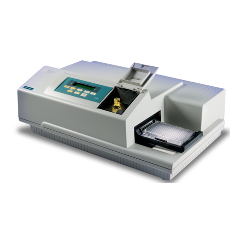
Figure 1.1
: SPECTRAmax 340PC
The Control Panel
Figure 1.2
: Control Panel
The control panel consists of an LCD and 15 pressure-sensitive membrane
keys—all the controls necessary to perform stand-alone operation of the SPEC-
TRAmax 340PC. The control panel can be used to configure the instrument set-
tings, store and recall assay protocols, and to initiate readings. When you press a
control panel key, the SPECTRAmax 340PC begins the desired action.
When using Molecular Devices’ SOFTmax PRO software to control the
SPECTRAmax 340PC from an external computer, the LCD will show
“Remote Control” during the time SOFTmax PRO is running. During
computer-controlled operation, the front control panel keys are disabled.
If you quit SOFTmax PRO, the LCD returns to normal and the front
control panel keys will function as before.
Control Panel Microplate
Drawer
Back Panel
NOTE:

Chapter 1
1-6 SPECTRAmax 340PC Microplate Spectrophotometer Operator’s Manual
LCD
The 2-
×
-40-character liquid crystal display shows the current instrument set-
tings. You can change the contrast of the display to appear darker or lighter as
desired. Press and hold the
[Shift]
key and then press the up or down arrow on
the
[AutoMix]
key. Pressing the up (
▲
) arrow makes the display lighter; pressing
the down (
▼
) arrow darkens the display.
Keys
Most stand-alone instrument functions can be performed by pressing a single
key; a few others require that you press keys in combination. The functions of the
control panel keys are described below.
[Setup]
Allows you to choose from a group of assay protocols that have been saved in
non-volatile memory (stored by number from 0 through 9). The settings stored
under “0” are factory preset defaults and cannot be modified or deleted. At the
time of shipment, settings 1 through 9 also contain the same preset defaults.
Non-volatile memory is retained even if the instrument is turned off.
[Save]
Stores the instrument settings you have chosen for the assay into memory under a
specific number from 1 through 9 (0 is reserved for the default instrument proto-
col).
[Recall]
Recalls the instrument settings previously stored using the
[Save]
key.
[\ 1 nm]
Selects the
measurement
wavelength. Pressing the up or down arrow key scrolls up
or down through the available wavelengths, starting at the previous setting. Press-
ing the up (
▲
) or down (
▼
) arrow
once
increments or decrements the wavelength
shown in the display by 1 nm; pressing and
holding
either arrow increments or
decrements the wavelength shown in the display by 10 nm until it is released. If
you increment the setting to the highest limit (850 nm) and continue pressing
the up (
▲
) arrow, the display returns to the lowest possible setting (340 nm) and
begins incrementing from there. The inverse is true for decrementing by pressing
the down (
▼
) arrow.
[\1-2 nm]
Selects the
reference wavelength. Pressing either the up (▲) or down (▼) arrow on
this key once increments or decrements the wavelength shown in the display by
1 nm; pressing and holding either arrow key increments or decrements the wave-
length shown in the display by 10 nm until it is released. If you increment the
setting to the highest limit (850 nm) and continue pressing the up (▲) arrow, the
display returns to the lowest possible setting (340 nm) and begins incrementing
from there. The inverse is true for decrementing by pressing the down (▼) arrow.
NOTE:

Instrument Description
SPECTRAmax 340PC Microplate Spectrophotometer Operator’s Manual 1-7
[On/Off] (λ1-2 nm)
Enables/disables dual wavelength mode.
[Read Mode]
Selects the read mode by scrolling through the listed options. Choices are Blank,
Endpoint, and Kinetic.
[Kinetic Run Time]
Allows you to choose the duration for a kinetic run. (Kinetic read mode must
have been chosen first for this key to be active.) Choices are 1, 2, 5, 10, and 20
minutes.
[Temp °C] (Incubator)
Allows you to enter a set point at which to regulate the microplate chamber tem-
perature. Pressing this key scrolls up or down, starting at the previous tempera-
ture setting (or the default of 37.0°C, if no setting had been made). Pressing the
up (▲) or down (▼) arrow once increments or decrements the temperature
shown in the display by 0.1°C; pressing and holding either arrow increments or
decrements the temperature shown in the display by 1°C until it is released. If
you increment the setting to the highest limit (45°C) and continue to press the
up (▲) arrow, the display will not change. If you decrement the setting to the
lowest limit, 15°C, and continue to press the down (▼) arrow, the display will
not change.
The temperature set point must be at least 4°C above ambient. The
ambient temperature must be greater than 20°C to achieve temperature
regulation of 45°C.
If the incubator is disabled, pressing the [Temp °C] key will
enable the incubator.
[On/Off] (Incubator)
Enables/disables the incubator function.
[Auto Mix]
Depending on the mode chosen, pressing this key selects automatic shaking of
the microplate for a preset duration at one or more points before and/or during
the read cycle. Choices are On, Once, and Off.
[Shift]
Activates secondary functions by first pressing and holding the [Shift] key fol-
lowed by pressing the secondary key. Labels for secondary functions are printed
in red on the control panel.
[CANCEL]
Stops the reading in progress. [CANCEL] is invoked by pressing the [Shift/
READ] key combination. [CANCEL] remains active when the instrument is in
remote control mode.
NOTE:
!CAUTION:
CANCEL

Chapter 1
1-8 SPECTRAmax 340PC Microplate Spectrophotometer Operator’s Manual
[Print]
Sends the data from the most recent reading to the printer (if it is connected
directly to the SPECTRAmax 340PC).
[Drawer]
Opens or closes the microplate drawer. Whether or not the drawer will remain
open depends on the incubator setting. If the incubator is off, the drawer will
remain open; if the incubator is on, the drawer will close after approximately
10 seconds to assist in maintaining temperature control within the microplate
chamber.
[READ]
Pressing this key causes the microplate drawer to close automatically, if it was
open, after which the selected assay read mode begins.
Status Indicators
At the far right of the LCD are indicators as shown in Figure 1.3. These indica-
tors will be illuminated when the SPECTRAmax 340PC is performing certain
actions as described below.
Figure 1.3: LCD Indicators
CALIBRATING Illuminated during the automatic calibration cycle before the
instrument reads the microplate.
READING Illuminated while the instrument is reading a microplate.
TEMPERATURE This indicator flashes when the incubator is turned on and
the set point has not yet been reached; it is illuminated con-
tinuously (no longer flashing) when the set temperature has
been reached (± 0.3°C).
BLANK ON Illuminated when a BLANK pattern is active.

Instrument Description
SPECTRAmax 340PC Microplate Spectrophotometer Operator’s Manual 1-9
The Microplate Drawer
Figure 1.4: Microplate Drawer
The microplate drawer, located on the right side of the SPECTRAmax 340PC,
holds microplates and blanking templates. The drawer slides in and out of the
microplate chamber. Springs on two sides of the drawer automatically position
and hold a microplate in the proper position. The drawer remains in the reading
chamber during read cycles.
Microplate drawer operation varies, depending upon the incubator status. When
the incubator is off, the microplate drawer remains open at power up and after a
read. When the incubator is on, the drawer closes automatically to assist in con-
trolling the temperature of the microplate chamber. To open the drawer, press the
[Drawer] key. The drawer will remain open for approximately ten seconds, after
which a beeping sound will alert you approximately two seconds before the
drawer closes automatically. After the read, the drawer will open for about 10 sec-
onds, allowing you to remove the plate.
During a kinetic read in either stand-alone mode or under computer
control, the drawer can be opened between reads by pressing the
[Drawer] button when there are at least 30 seconds before the next read.
The drawer will close automatically before the next read.
Do not obstruct the movement of the drawer. If you must retrieve a plate
after an error condition or power outage and the drawer will not open, it
is possible to open it manually (see Chapter 5, “Troubleshooting”).
Microplates
The SPECTRAmax 340PC can accommodate standard 96-well microplates,
strip wells, and filter-bottom microplates. Not all manufacturers’ microplates are
the same with regard to design, materials, or configuration. Temperature unifor-
mity within the microplate may vary depending on the type of microplate used.
Templates
Blank pattern templates supplied with the SPECTRAmax 340PC can be used in
stand-alone mode to select a blank set of wells. More information regarding the
use of templates and creating blank patterns can be found Chapter 3, “Stand-
Alone Operation.”
A1 Indicator
NOTE:
NOTE:

Chapter 1
1-10 SPECTRAmax 340PC Microplate Spectrophotometer Operator’s Manual
The Back Panel
Figure 1.5: Components on the Back Panel of the SPECTRAmax 340PC
The following components are located on the back panel of the SPECTRAmax
340PC:
•Power switch—a rocker switch, labeled I/O (for on and off, respectively).
•Power cord receptacle—plug the power cord in here.
•Fuse box cover—cannot be opened while the power cord is plugged in. When
opened, it provides access to the fuse box containing two fuses that are required
for operation.
•Printer port (double-shielded, 25-pin parallel, for use in stand-alone opera-
tion)—plug the 25-pin end of the cable into this port; the other (Centronics)
end attaches to a port on the printer.
•Computer port (double-shielded RS-232, for use with an external com-
puter)—plug one end of an 8-pin DIN serial cable into this port; the other end
attaches to the serial (modem) port of the computer.
•Label—provides information about the SPECTRAmax 340PC, such as line
voltage rating, cautionary information, serial number, etc. Record the serial
number shown on this label on the Warranty Card and for use when contacting
Molecular Devices Technical Services.
Computer Printer
Power Switch
Fuse Box Cover
Power Cord
Receptacle
Label
(RS-232) Port Port

Instrument Description
SPECTRAmax 340PC Microplate Spectrophotometer Operator’s Manual 1-11
Functional
Description
Instrument Settings
Up to nine user-definable assay protocols can be saved in non-volatile memory
for future use. User-defined protocols are saved by number (1-9); the protocol
labeled “0” contains default parameters, set at the factory, and cannot be altered.
User-defined protocols can contain the following instrument settings:
•Read mode
•Wavelength(s) (up to two)
•Automix state
•Blank pattern
•Temperature set point
Assay protocol settings that you save under numbers 1 through 9 are retained by
the SPECTRAmax 340PC in non-volatile memory—they are retained even
when power to the instrument is turned off. At power up, the SPECTRAmax
340PC always reverts to the default protocol 0, but the other saved settings are
available.
Saving a Protocol
To store a protocol in memory, first define the instrument settings for the proto-
col by setting the parameters as desired. Then press the up or down arrows on the
[Setup] key until the desired number (under which to save the protocol) is dis-
played. Then press the [Save] key to save the current protocol in non-volatile
memory under that number.
If any settings were already saved under that number, they will be over-
written by this process. Before choosing a number under which to save
parameters, ensure first that it does not contain data you wish to retain.
Recalling a Saved Protocol
To recall a protocol that you saved previously, press the up or down arrows on the
[Setup] key until the number of the saved protocol (from 1 to 9) appears in the
display and then press [Recall].
To restore the factory-default protocol and overwrite any settings in present
memory, press [Setup], choose “0,” and then press [Recall]. To replace the set-
tings for any protocol stored under numbers 1 through 9 with these factory
default settings, use [Setup] to select the desired protocol number and then press
[Save].
NOTE:

Chapter 1
1-12 SPECTRAmax 340PC Microplate Spectrophotometer Operator’s Manual
Modes of Stand-Alone Operation
When operating the SPECTRAmax 340PC as a stand-alone system, you can
obtain readings using either endpoint or kinetic mode.
Endpoint
If you wish to obtain a single set of optical density (OD) readings for each well of
a microplate, select either single- or dual-wavelength operation in endpoint
mode. OD data is printed in an 8-×-12 microplate format.
When the instrument is set to endpoint mode, the ten-second read cycle (for each
wavelength selected) is automatically preceded by a calibration cycle requiring
approximately one second.
Dual wavelength readings are taken at a measurement wavelength (λ1) as well as
a reference wavelength (λ2)—you may choose both settings. The difference
between these readings (λ1-λ2) is displayed for each well.
If the Automix function is selected for endpoint readings, the plate is shaken for
five seconds prior to the reading.
Kinetic
Kinetic analysis at a single wavelength (λ1) can be performed for several pre-
defined total reading times (1, 2, 5, 10, and 20 minutes) with preset read inter-
vals. At the end of a reading, rates are reported as mOD/min for each well in an
8-×-12 microplate format.
Kinetic analysis has many advantages when determining the relative activity of an
enzyme in different types of microplate assays, including ELISAs and the purifi-
cation and characterization of enzymes and enzyme conjugates. Kinetic analysis is
capable of providing improved dynamic range, precision, and sensitivity relative
to endpoint analysis.
In kinetic mode, a calibration cycle requiring less than one second automatically
precedes the first read cycle. During the kinetic reading, the microplate remains
in the isothermal microplate chamber. The interval between read cycles is deter-
mined by the instrument based on the kinetic run time and the Automix status.
If Automix is selected for kinetic analysis, the microplate is shaken for five sec-
onds prior to the initial reading. Thereafter the microplate is shaken for three sec-
onds before each read cycle. This ensures that the color developing in each well is
uniformly distributed throughout the well prior to each reading. The Automix
function is strongly recommended for ELISAs and other solid-phase, enzyme-
mediated reactions.
The SPECTRAmax 340PC calculates the rate of reaction for each well, for either
positive or negative kinetic rates, using the first reading as the starting OD base-
line value for each well and a limited OD excursion of 0.2 OD. The on-board,
microprocessor-based, linear regression package reports the slope value for the
line fit to each kinetic plot as the kinetic rate in mOD/min.
Table of contents
Other Molecular Devices Measuring Instrument manuals

Molecular Devices
Molecular Devices SPECTRAmax PLUS 384 User manual

Molecular Devices
Molecular Devices SpectraMax i3x User manual

Molecular Devices
Molecular Devices SPECTRAmax PLUS 384 User manual

Molecular Devices
Molecular Devices FlexStation II User manual

Molecular Devices
Molecular Devices SpectraMax 190 User manual

Molecular Devices
Molecular Devices SpectraMax ABS User manual

Molecular Devices
Molecular Devices Digidata 1550B User manual

Molecular Devices
Molecular Devices MiniDigi User manual

Molecular Devices
Molecular Devices SpectraMax 340PC384 User manual