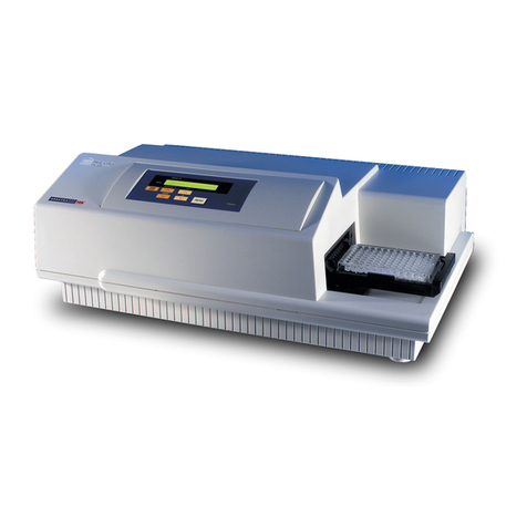
Molecular Devices FlexStation II User manual

FlexStation™II and FlexStation™II384
Benchtop Scanning Fluorometer
and Integrated Fluid Transfer Workstation
Operator’s Manual
PN 0112-0077 – Rev. D

Revision History:
Date Revision Version Description
03/01 A 1.0 Initial release.
05/01 B 1.1 Text changes.
08/01 C 1.2 Text changes.
03/03 D 1.3 Text changes.
Molecular Devices Corporation
1311 Orleans Drive
Sunnyvale, CA 94089 USA
Tel: 408.747.1700
Online: www.moldev.com
Sales Offices
USA/Canada 800.635.5577
UK +44.118.944.8000
Germany: +49.89.9620.2340
Japan +81.797.32.2877
Copyright
© Copyright 2003, Molecular Devices Corporation. All rights reserved. No part of
this publication may be reproduced, transmitted, transcribed, stored in a retrieval
system, or translated into any language or computer language, in any form or by
any means, electronic, mechanical, magnetic, optical, chemical, manual, or
otherwise, without the prior written permission of Molecular Devices Corporation,
1311 Orleans Drive, Sunnyvale, California, 94089, United States of America.
Patents
The FlexStation instrument and methods have US and International patents
pending.
Trademarks
SPECTRAplate and AUTOMIX are trademarks and FlexStation and SOFTmax are
registered trademarks of Molecular Devices Corporation. Cliniplate is a registered
trademark of Labsystems. DELFIA is a registered trademark of Wallac Oy.
Emerald II is a trademark of Tropix, Inc. All other company and product names are
trademarks or registered trademarks of their respective owners.
Disclaimer
Molecular Devices Corporation reserves the right to change its products and
services at any time to incorporate technological developments. This manual is
subject to change without notice. Although this manual has been prepared with
every precaution to ensure accuracy, Molecular Devices Corporation assumes no
liability for any errors or omissions, nor for any damages resulting from the
application or use of this information.
ii FlexStation II Operator’s Manual – Rev. D

Contents
1 System Description................................................... 1
1.1 Introduction.......................................................... 1
1.2 Operator’s Manual Overview ............................................ 3
1.3 Safety Information .................................................... 4
1.4 System Components................................................... 6
1.4.1 Covers and Instrument Panels ....................................... 7
1.4.2 Drawers........................................................ 9
1.4.3 Fluidics Module ................................................ 11
1.4.4 Detection Module ............................................... 13
1.4.5 Computer ..................................................... 15
1.4.6 Accessories..................................................... 16
1.4.7 Consumables................................................... 17
1.5 Overview of Operation ................................................ 18
1.6 Theory of Operation .................................................. 19
1.6.1 Introduction to Fluorometry ....................................... 19
1.6.2 Instrument Design............................................... 21
1.6.3 Modes of Operation ............................................. 24
1.7 Introduction to SOFTmax PRO Application Software ........................ 27
2 Installation Procedures .............................................. 31
2.1 General Precautionary Information ...................................... 31
2.2 Unpacking the System ................................................ 32
2.3 Installing the Fluidics Module........................................... 35
2.4 Installing the Pipettor Head ............................................ 37
2.5 Setting Up the Computer .............................................. 40
2.6 Connecting the Cables ................................................ 41
2.7 Installing the Drawer Adapters.......................................... 42
2.8 Installing SOFTmax PRO ............................................... 42
3 Operating Procedures ............................................... 43
3.1 Overview ........................................................... 44
3.2 Starting Up the System ............................................... 45
3.3 Setting the Temperature............................................... 49
FlexStation II Operator’s Manual – Rev. D iii

Contents
3.3.1 Displaying Temperature .......................................... 49
3.3.2 Setting the Temperature with the Control Panel ........................ 49
3.3.3 Setting the Temperature with SOFTmax PRO ......................... 50
3.4 Setting Up the Software ............................................... 51
3.5 Configuring Instrument Settings in Flex Mode ............................. 54
3.5.1 Wavelengths ................................................... 55
3.5.2 Sensitivity ..................................................... 57
3.5.3 Timing ....................................................... 58
3.5.4 Automix ...................................................... 59
3.5.5 AutoCalibrate .................................................. 59
3.5.6 Assay Plate Type ................................................ 60
3.5.7 Wells to Read .................................................. 61
3.5.8 Compound Source .............................................. 63
3.5.9 Compound Transfer ............................................. 64
3.5.10 Triturate Selection............................................... 67
3.5.11 Pipette Tips Layout .............................................. 68
3.5.12 Compound and Tip Columns ...................................... 69
3.5.13 AutoRead ..................................................... 72
3.5.14 Pipette Tip Air Gap.............................................. 72
3.5.15 Settings Displayed in Plate Sections.................................. 73
3.6 Other Software Settings ............................................... 74
3.7 Reading the Microplate................................................ 75
3.8 Shutdown .......................................................... 78
3.9 Other Read Modes.................................................... 78
3.10 Optimizing Fluorescence Assays in Spectrum Mode......................... 79
4 Applications.......................................................... 85
5 Service and Maintenance Procedures .............................. 87
5.1 Technical Support .................................................... 87
5.2 Moving the Instrument ................................................ 88
5.3 Cleaning the Instrument ............................................... 88
5.4 Using the Microplate Adapters.......................................... 89
5.5 Using the Compound Baseplate ......................................... 89
5.6 Replacing Fuses...................................................... 90
5.7 Replacing the Flash Lamp .............................................. 92
5.8 Long-Term Shutdown ................................................. 95
iv FlexStation II Operator’s Manual – Rev. D

Contents
6 Troubleshooting Procedures........................................ 97
6.1 Problems During Startup .............................................. 97
6.2 Opening a Drawer Manually ............................................ 99
6.3 Understanding Potential Mechanical Problems............................ 100
6.3.1 Background................................................... 100
6.3.2 Before Using the Instrument ...................................... 100
6.3.3 Avoiding Mechanical Problems .................................... 101
6.3.4 In Case of Power Failure ......................................... 101
6.4 Recovering from Mechanical Problems in Flex Mode ....................... 102
6.4.1 Assessing a Mechanical Problem ................................... 103
6.4.2 Opening the Instrument ......................................... 104
6.4.3 Evaluating the Tip Rack ......................................... 105
6.4.4 Inspecting Inside the Fluidics Module ............................... 106
6.4.5 Removing the Pipettor Head ...................................... 109
6.4.6 Expelling Undispensed Fluid from Tips.............................. 111
6.4.7 Recovery Procedure ............................................. 112
6.5 General Error Messages .............................................. 113
6.6 Tilting or Removing the Fluidics Module ................................. 115
6.6.1 Tilting the Fluidics Module....................................... 116
6.6.2 Removing the Fluidics Module .................................... 117
7 Appendices.......................................................... 119
7.1 Parts and Accessories ................................................ 119
7.2 Performance Specifications ........................................... 120
7.3 Warranty .......................................................... 122
7.4 Index ............................................................. 123
FlexStation II Operator’s Manual – Rev. D v

FlexStation II Operator’s Manual – Rev. D vi

1 System Description
Part 1 of this manual provides background information on the system, including
descriptions of the principal components and overviews of how the system functions. It
is divided into the following sections:
• 1.1: Introduction
• 1.2: Operator’s Manual Overview
• 1.3: Safety Information
• 1.4: System Components
• 1.5: Overview of Operation
• 1.6: Theory of Operation
• 1.7: Introduction to SOFTmax PRO Application Software
1.1 Introduction
FlexStation™ II Systems provide integrated fluid transfer capability from a source plate
or reservoir to an assay plate with concurrent kinetic fluorometric analysis of reactions.
Data collection speed is sufficient for running fast cell-based kinetic assays. The
instruments feature a bottom-read mode ideal for whole-cell-based assays, and may be
automatically switched to a top-read mode for solution-phase reactions.
FlexStation II Systems can be used for drug discovery research and development,
secondary and post screen analysis. The instruments are available in two models:
• The FlexStation™ II instrument is designed specifically for 96-well microplates.
• The FlexStation™ II³⁸⁴ instrument is designed for 96- and 384-well microplates.
The instruments offer 96- and 384-well microplate-to-microplate fluid transfer (8 or 16
wells at a time), and can read microplates having 6, 12, 24, 48, 96, and 384-well
formats. Top or bottom detection is available with a simple click of a button.
A microplate adapter is required in the reading chamber drawer for 96- and 384-well
assay plates, for both bottom and top reading. The black adapter allows for optimal
signal for bottom readings, and the purple adapter optimizes top-read scenarios. A
different baseplate is provided for the compound plate drawer.
The instrument is controlled by an external personal computer running the SOFTmax®
PRO software, which provides integrated instrument control, data display, and statistical
data analysis.
The system can perform a variety of fluorescence applications, as well as some limited
time-resolved fluorescence and luminescence operations. The system’s extreme flexibility
and high sensitivity make it appropriate for applications in biochemistry, cell biology,
immunology, molecular biology, and microbiology. The instrument uses two
holographic diffraction grating monochromators that allow for individual optimization
of both excitation and emission wavelengths. The dual-scanning capability can also be
used to determine excitation and emission settings for new fluorescent probes. Mirrored
FlexStation II Operator’s Manual – Rev. D 1

1 System Description
optics focus the light into the sample, and cutoff filters reduce stray light and minimize
background interference. The light source is a high-power xenon flash lamp. The system
provides additional flexibility by allowing a variable number of lamp flashes per reading.
The temperature in the microplate reading chamber is isothermal, both at ambient and
when the incubator is turned on. When the incubator is on, the system controls the
incubator temperature from 1 °C above ambient to 45 °C.
The system operates in one integrated fluidics/read mode and four read-only modes.
Using the Automix feature, the contents of the wells in a microplate can be mixed
automatically by shaking, which makes it possible to perform kinetic analysis of solid-
phase, enzyme-mediated reactions such as a kinetic ELISA. In Flex mode, the pipettor
can also be used to mix the contents of the compound plate or the assay plate, a
procedure called trituration.
actual˚C
set pt˚C
Set Temp
Temp
on/off
Drawers
reading
chamber
compounds
tip rack
FlexStation™ II Instrument
2FlexStation II Operator’s Manual – Rev. D

1.2 Operator’s Manual Overview
This manual was written to ensure safe and proper use of the system. Before use, read
this manual carefully in order to realize the full capabilities of the system. Also, if
something is unclear during daily use or if a problem occurs, please refer to this manual.
This manual is organized as follows:
Part 1: System Description provides background information on the system, including
descriptions of the principal components and overviews of how the system functions.
Part 2: Installation Procedures provide instructions for assembling the instrument and
installing the SOFTmax PRO application on your Windows-based computer.
Part 3: Operating Procedures provides instructions for operating the system with the
SOFTmax PRO application software in Flex fluidics + read mode.
Part 4: Applications provides a space for detailed protocols for several FlexStation II
mode experiments.
Part 5: Service and Maintenance Procedures provide instructions for routine mainte-
nance including replacing the lamp, changing the pipettor head, moving the system to a
new location, and minor cleaning.
Part 6: Troubleshooting Procedures provide instructions for diagnosing and solving
common problems, as well as a list of error conditions.
Part 7: Appendices provides technical specifications, a list of spare parts, the index, and
warranty statement.
Conventions Used in this Manual
The names of keys that appear on the FlexStation II control panel and icons that appear
in the SOFTmax PRO software are shown in boxed type. Example: [Start].
The term ‘instrument’ refers generally refers to the fluidics and detection modules.
‘System’ refers generally to all the components (detection module, fluidics module,
computer, software, accessories, and consumables).
FlexStation II Operator’s Manual – Rev. D 3

1 System Description
1.3 Safety Information
When operated properly in a safe environment and according to the instructions in this
manual, there are no known hazards associated with the FlexStation II System. However,
proper use requires an understanding of situations that are potentially dangerous and can
result in serious injury. All users must be familiar with the guidelines in this section
before working with the system.
Conventions Used for Precautionary Information
This manual uses the following conventions to provide technical and safety information
of special interest.
Note: Background information provided to clarify a particular step or procedure.
Caution: An instruction that, if not followed, can result in damage to the system.
Important! An instruction provided to ensure correct results and optimal performance.
An instruction that, if not followed, could result in loss of data.
Warning! An instruction that, if not followed, can result in potential injury to a person
working with the system.
Biohazard:Indicates a condition involving potentially infectious biological agents
requiring that proper handling precautions be taken.
Electrical Safety
Warning! Follow all instructions in this manual and on system labels. If you use the
system in a manner not specified by Molecular Devices, any protections provided by the
system may be impaired.
Service-Trained Users
There are two types of users described in this manual. Most procedures required for
operating and troubleshooting can be performed by any user who has read the
instructions in this manual and is familiar with the system. However, all installation
procedures, and some more complex service and troubleshooting procedures, require the
expertise of a service-trained user. Whenever the following warning message appears, a
service-trained user must perform the procedure to ensure user safety and to prevent
instrument damage.
Example: Warning! The following procedures must be completed by a service-
trained user. Do not attempt the following procedures if you have not been
trained properly by appropriate Molecular Devices personnel.
Avoiding Mechanical Problems In Flex Mode
Because of the complex mechanical nature of the FlexStation II instrument, including
both fluidics and optical reading, smooth and reliable operation of the system depends
on both good design and operator knowledge.
In order to prevent problems of a mechanical nature, be sure to read all sections of this
manual prior to attempting a reading in Flex mode. See especially section 6.3,
Understanding Potential Mechanical Problems.
4FlexStation II Operator’s Manual – Rev. D

1.3 Safety Information
Safety Messages
Observe the following warnings and precautions:
High internal voltages. Always turn off power switch and unplug system power cord
before removing labeled covers or panels.
Xenon-arc flash lamp. Do not look directly at the flash lamp while illuminated. The
lamp emits ultraviolet radiation at levels that can injure the eye if viewed directly.
Electrical grounding. Never use a two-prong plug or extension cord to connect primary
power to the system. Use of a two-prong adapter disconnects the utility ground, creating
a severe shock hazard. Always connect the system power cord directly to a three-prong
receptacle with a functional ground.
Spilled liquids. Avoid spilling liquids on the system. Fluid spilled into internal com-
ponents creates a potential shock hazard. Wipe up all spills immediately. Do not operate
the system if internal components have been exposed to spilled fluid. Unplug instrument
if there is a fluid spill in the instrument and contact Technical Support.
Replacement fuses. Use replacement fuses with the required current rating and
specification. Improper fuses or short-circuiting the fuse holders can cause fire or damage
the instrument.
Power rating. Ensure the system is connected to a power receptacle that provides voltage
and current within the specified rating for the system. Use of an incompatible power
receptacle can create electrical shock and fire hazards.
Remove watches and jewelry before removing any panels from the instrument.
Warning labels. There are several labels affixed to the instrument covers and inside
panels. The purpose of these labels is to alert you to use caution when servicing a
component or the instrument. Be aware that ignoring the instructions on any instrument
label can result in a hazardous condition that can cause injury.
Identification Labels: The following labels, among others, appear on the instrument.
US
C
FlexStation II FlexStation II
384
100-240V 5A 50-60 Hz FUSE: T6.3 AH
SLO-BLO
~
Molecular Devices
1311 Orleans Drive, Sunnyvale
CA 94089 408 747-1700
100-240V 5A 50-60 Hz FUSE: T6.3 AH
SLO-BLO
~
Molecular Devices
1311 Orleans Drive, Sunnyvale
CA 94089 408 747-1700
FlexStation II Operator’s Manual – Rev. D 5

1 System Description
1.4 System Components
This section describes the major system components listed below.
• 1.4.1: Covers and Instrument Panels
• 1.4.2: Drawers
• 1.4.3: Fluidics Module
• 1.4.4: Detection Module
• 1.4.5: Computer
• 1.4.6: Accessories
• 1.4.7: Consumables
actual˚C
set pt˚C
Set Temp
Temp
on/off
Drawers
reading
chamber
compounds
tip rack
Instrument, Front View
FLEXstation
™
100-240V~ 5A 50-60 Hz T6.3 AH
s/n FS 01001
C
NRTL/C
LR88026
"PATENTSPENDING"
US
Instrument, Rear View
6FlexStation II Operator’s Manual – Rev. D

1.4 System Components
1.4.1 Covers and Instrument Panels
Top Cover
The instrument is protected by a molded plastic housing. The large top cover protects
the fluidics module and the exposed portions of the detection module.
Note: The top cover can be lifted back, as shown in the figure below, for certain limited
troubleshooting procedures. See section 6.4.2, Opening the Instrument.
Important! To achieve optimal performance during readings, you must operate the
system with the top cover in place.
actual˚C
set pt˚C
SetTemp
Temp
on/off
Drawers
reading
chamber
compounds
tip rack
Lifting Off the Top Cover
Control Panel
The control panel consists of an LCD and six pressure-sensitive membrane keys which
can be used to initiate and regulate the temperature and to open/close the drawers.
A 2 × 3-character liquid crystal display (LCD) shows the current instrument temperature
at all times, and the set point temperature when the incubator is on.
Note: See sections 3.2, Starting Up the System, and 3.3, Setting the Temperature, for
information about using the control panel.
actual˚C
set pt˚C
Set Temp
Temp
on/off
Drawers
reading
chamber
compounds
tip rack
Control Panel
FlexStation II Operator’s Manual – Rev. D 7

1 System Description
Input/Output Panels
There are two input/output panels on the rear of the instrument.
• The upper input/output panel, on the back cover, consists of a power switch, fuse
box cover, and power cord receptacle.
• The lower panel consists of an RS-232 serial port and parallel port (not currently
active). There are also a number of labels.
Note: See section 2.6, Connecting the Cables, for information about attaching the
computer cable and power cords to the instrument.
FLEXstation
™
100-240V~ 5A 50-60 Hz T6.3 AH
s/n FS 01001
CNRTL/C
LR88026
"PATENTS PENDING"
US
Parallel Port
(not currently in use)
RS-232 Serial Port
Power Cord Receptacle
RS-232 Serial Cable
Power Cord
Fuse Box Cover
Power Switch
Input/Output Panels
Lamp Cover
The plastic lamp cover provides access to the flash lamp on the right side of the
instrument (as viewed from the rear).
Note: For further information, see section 5.7, Replacing the Flash Lamp.
Caution: Flash lamp access and maintenance are restricted to service-trained users.
Lamp Cover
Rear View
8FlexStation II Operator’s Manual – Rev. D

1.4 System Components
1.4.2 Drawers
The instrument has three drawers that open on the right side. The two drawers in the
fluidics module open and close to move the pipette tip rack and compound plates (or
reservoirs) into and out of the instrument. The reading chamber drawer in the detection
module transports the assay microplate into the reading chamber.
actual˚C
set pt˚C
Set Temp
Temp
on/off
Drawers
reading
chamber
compounds
tip rack
Tip Rack Drawer
Compound Plate Drawer
Reading Chamber Drawer
Instrument with Drawers Open and Carriages Accessible
Small plastic pushers, located in the front left corner of each drawer, hold the plates,
racks, or reservoirs, securely in place when the drawers are closed
Carrier
Pusher
Drawer Detail
Caution: Do not obstruct the movement of any of the drawers. If you must retrieve a
plate after an error condition or power outage, and if the drawer will not open, it is
possible to open the drawer manually. See section 6.2, Opening a Drawer Manually.
FlexStation II Operator’s Manual – Rev. D 9

1 System Description
You can open and close the drawers using either the SOFTmax PRO
application or by manually pressing the drawer keys on the instrument control
panel.
Using SOFTmax PRO, go the Control menu and select Tip drawer (for the
tip rack drawer), Compound Drawer (for the compound plate drawer), or
Open Drawer (for the reading chamber drawer).
You can also open or close the reading chamber drawer with the Drawer icon on the
Status Bar.
Tip Rack Drawer
The top drawer holds the pipette tip rack.
Only tips specified by Molecular Devices for use with the FlexStation II System can be
safely used. For further information, see section 7.1, Parts and Accessories.
Caution: Do not use parts and accessories that are not authorized, specified by or
provided by Molecular Devices. Using unauthorized parts can damage the instrument.
Compound Plate Drawer
The compound plate drawer holds a 96- and 384-well microplate or reservoir trough.
The instrument can simultaneously transfer a column of either:
• Eight fluids from a 96-well compound plate to a 96-well assay plate, or
• Sixteen fluids from a 384-well compound plate to a 384-well assay plate.
Important! Be sure to install the compound baseplate before placing a compound plate
in the drawer.
Reading Chamber Drawer
The reading chamber drawer opens to accept a 96- and 384-well microplate for analysis
in the reading chamber. It is the lowest of the three drawers.
The reading chamber drawer operation varies, depending on the incubator status. When
the incubator is off, the reading chamber drawer is open at power up and after a read.
When the incubator is on, the drawer closes automatically to maintain the temperature
of the reading chamber.
Important! Be sure to install a microplate adapter before placing an assay plate in the
drawer (for standard microplates). For further information, see section 2.7, Installing the
Drawer Adapters.
10 FlexStation II Operator’s Manual – Rev. D

1.4 System Components
1.4.3 Fluidics Module
The fluidics module houses the pipettor head, several motors, and all the fluidics
components. There are two horizontally-moving carriers, one for the pipette tip rack and
the other for the compound plate. The pipettor head moves vertically between the
drawers.
The fluidics module can be opened, by service-trained users, from the inside front panel,
if necessary for maintenance, or from the inside top panel to install or remove the
pipettor head. The entire fluidics module can be removed for maintenance or to
transport the system to another location.
For further information, see 2.3, Installing the Fluidics Module. See part
6, Troubleshooting Procedures, for related service procedures.
Inside Front Panel
Detection Module
Inside Top Panel
Fluidics Module
Fluidics Module
FlexStation II Operator’s Manual – Rev. D 11

1 System Description
Pipettor Head
The instrument is configured with an eight-channel pipettor head for use with 96-well
microplates. In addition, the FlexStation II³⁸⁴ includes a 16-channel pipettor head for
use with 384-well microplates.
Note: For further information, see 2.4, Installing the Pipettor Head.
Eight- or
Sixteen-Channel
Pipettor Head
Inside Top Panel
Opened
Pipettor Head
12 FlexStation II Operator’s Manual – Rev. D

1.4 System Components
1.4.4 Detection Module
The detection module is the lower portion of the instrument. This module houses the
reading chamber, the optics bench, several cables and optic fibers, the power supply, the
flash lamp, and other hardware. The fluidics module attaches to the detection module
and can be tilted off to the side, to provide access to the optical system for
troubleshooting or maintenance. The detection module is contained in a molded plastic
housing, to which the top cover is attached at the back of the instrument.
Reading Chamber
Drawer with Assay Plate
Top Cover
Housing
Reading Chamber
Detection Module
Fluidics Module
Detection Module Detail
Reading Chamber
The reading chamber includes the assay plate carriage, which holds the assay microplate
in the reading chamber during read cycles. The reading chamber may be maintained at
an elevated temperature. It contains both top and bottom read heads, which can be
selected via software command.
The instrument utilizes a plate sensor to assure that an assay plate is present in the
reading chamber before a reading begins.
FlexStation II Operator’s Manual – Rev. D 13

1 System Description
Optical System
The optical system includes a xenon flash lamp, the monochromators, excitation
bandpass filters, emission cut-off filters, and a PMT detector.
There are a number of cables and fibers that exit the optics bench and enter the read
chamber. They are the excitation fiber (thin and black, has a collar and pins), emission
fiber (fatter, with attached electrical cord), electrical connector to the read head (black
with brass fitting).
Caution: Optical fibers are very fragile, especially the excitation fiber. Handle cables with
extreme care. Do not flex, twist, bend, or stretch the optical cables.
Flash Lamp
Photomultiplier
Tube
Excitation
Monochromator
Microplate
Elliptical Focusing
Mirrors
Emission
Monochromator
Flash Lamp
Collimation
Mirror
Optical System
Overview of Optical System
1 The excitation light source is a xenon-arc flash lamp. (Note that the lamp is off when
luminescence mode is selected.)
2 The light passes through a band-pass filter which reduces the amount of stray light to the
excitation monochromator.
3 The holographic diffraction grating monochromator selects the desired excitation
wavelength.
14 FlexStation II Operator’s Manual – Rev. D
This manual suits for next models
1
Table of contents
Other Molecular Devices Measuring Instrument manuals
Molecular Devices
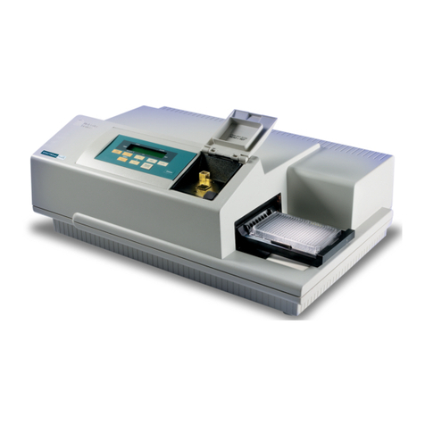
Molecular Devices SPECTRAmax 340PC User manual

Molecular Devices
Molecular Devices SPECTRAmax PLUS 384 User manual
Molecular Devices
Molecular Devices Digidata 1550B User manual

Molecular Devices
Molecular Devices SpectraMax i3x User manual

Molecular Devices
Molecular Devices SpectraMax 340PC384 User manual

Molecular Devices
Molecular Devices SPECTRAmax PLUS 384 User manual

Molecular Devices
Molecular Devices SpectraMax 190 User manual
Molecular Devices
Molecular Devices MiniDigi User manual
Molecular Devices
Molecular Devices SpectraMax ABS User manual